

Page 1

R7ML-DC16A
P. 1 / 10
EM-7805-G Rev.2
5-2-55, Minamitsumori, Nishinari-ku, Osaka 557-0063 JAPAN
Phone: +81(6)6659-8201 Fax: +81(6)6659-8510 E-mail: info@m-system.co.jp
NPN TRANSISTOR OUTPUT MODULE, 16 points
(MECHATROLINK-I / -II)
MODEL
R7ML-DC16A
INSTRUCTION MANUAL
BEFORE USE ....
Thank you for choosing M-System. Before use, please check
contents of the package you received as outlined below.
If you have any problems or questions with the product,
please contact M-System’s Sales Office or representatives.
■ PACKAGE INCLUDES:
Discrete output module .............................................. (1)
■ MODEL NO.
Confirm that the model number described on the product is
exactly what you ordered.
■ INSTRUCTION MANUAL
This manual describes necessary points of caution when
you use this product, including installation, connection and
basic maintenance procedures.
POINTS OF CAUTION
■ CONFORMITY WITH EU DIRECTIVE
• Use MECHATROLINK-II network cable with core (Yasukawa Controls Model JEPEC-W6003-x-E) or equivalent
for the network.
• Be sure to earth FG terminal.
• The actual installation environments such as panel con-
figurations, connected devices and connected wires may
affect the protection level of this unit when it is integrated in a panel system. The user may have to review the CE
requirements in regard to the whole system and employ
additional protective measures to ensure CE conformity.
■ POWER INPUT RATING & OPERATIONAL RANGE
• Locate the power input rating marked on the product and
confirm its operational range as indicated below:
24V DC rating: 24V ±10%, approx. 85mA
■ GENERAL PRECAUTIONS
• Before you remove the unit or mount it, turn off the power
supply and input signal for safety.
■ ENVIRONMENT
• Indoor use.
• When heavy dust or metal particles are present in the
air, install the unit inside proper housing with sufficient
ventilation.
• Do not install the unit where it is subjected to continuous
vibration. Do not subject the unit to physical impact.
• Environmental temperature must be within 0 to 55°C (32
to 131°F) with relative humidity within 30 to 90% RH in
order to ensure adequate life span and operation.
■ WIRING
• Do not install cables close to noise sources (relay drive
cable, high frequency line, etc.).
• Do not bind these cables together with those in which noises are present. Do not install them in the same duct.
• FG terminal is NOT a protective conductor terminal.
■ AND ....
• The unit is designed to function as soon as power is supplied, however, a warm up for 10 minutes is required for
satisfying complete performance described in the data
sheet.
Page 2

R7ML-DC16A
P. 2 / 10
EM-7805-G Rev.2
5-2-55, Minamitsumori, Nishinari-ku, Osaka 557-0063 JAPAN
Phone: +81(6)6659-8201 Fax: +81(6)6659-8510 E-mail: info@m-system.co.jp
COMPONENT IDENTIFICATION
5
4
3
2
1
0
9
8
7
6
ERR
RD
RUN SD
PWR
X10 X1
STATION ADD. B. RATE
CNFG.
1 2 3 4 5 6 7 8
0 1 2 3 4 5 6 7 8 9 A B C D E F
4567
123
10 11 12 13
2341
15 16 17 18
7896145
MECHATROLINK Setting Rotary SW
MECHATROLINK
Connector
Station Address Setting
Rotary SW
Status Indicator LED
Operating Mode Setting DIP SW (SW1)
PC Configurator Jack
Discrete Output Status Indicator LED
Power Supply Terminals
MECHATROLINK Connector
Output Terminals
■ LEFT SIDE VIEW
■ FRONT VIEW
8
9
A
B
C
D
E
F
0
1
2
3
4
5
6
7
8
9
A
B
C
D
E
F
0
1
2
3
4
5
6
7
Page 3
R7ML-DC16A
P. 3 / 10
EM-7805-G Rev.2
5-2-55, Minamitsumori, Nishinari-ku, Osaka 557-0063 JAPAN
Phone: +81(6)6659-8201 Fax: +81(6)6659-8510 E-mail: info@m-system.co.jp
■ STATUS INDICATOR LED
ID COLOR FUNCTION
PWR Green
Turns on when the internal 5V is supplied
normally.
RUN Green Turns on in normal communications
conditions.
ERR Red Turns on in no communication or setting
error.
SD Green Turns on when the module is transmit-
ting.
RD Green Turns on when the module is receiving.
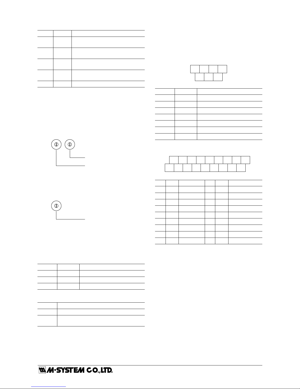
■ STATION ADDRESS
Station Address is selected between 60H and 7FH (Intelligent I/O) in hexadecimal. (Certain numbers may not be
selectable depending on the master types. Refer to the instruction manual of the master unit.)
The left switch determines the MSD, while the right switch
does the LSD of the address.
(Factory setting: 60H)
Station Address Setting (LSD)
Station Address Setting (MSD)
8
9
A
B
C
D
E
F
0
1
2
3
4
5
6
7
8
9
A
B
C
D
E
F
0
1
2
3
4
5
6
7
■ MECHATROLINK MODE
Choose MECHATROLINK-I or -II, and the data size. Positions 2, 4 through 9 are unused.
(Factory setting: 1)
5
4
3
2
1
0
9
8
7
6
MECHATROLINK Setting
0 : MECHATROLINK-II (32-byte mode)
1 : MECHATROLINK-II (17- byte mode)
3 : MECHATROLINK-I (17- byte mode)
■ EXTENSION MODULE
Combinations with any extension module is selectable.
■ OPERATING MODE
(*) Factory setting
• Extension (SW1-1, 1-2)
SW1-1 SW1-2 Extension
OFF OFF No extension (*)
ON OFF Discrete input, 8 or 16 points
OFF ON Discrete output, 8 or 16 points
• Output at the loss of communication (SW1-4)
SW1-4 Output at the loss of communication
OFF Reset the output (turned off)
ON Hold the output (*)
(maintains the last data received normally)
Caution ! - SW1-3, 1-5, 1-6, 1-7, 1-8 are unused. Be sure to turn
off unused ones.
■ DISCRETE OUTPUT STATUS INDICATOR LED
Discrete output modules have LED indicators showing output signal status.
Contact ON : LED ON
Contact OFF : LED OFF
■ POWER SUPPLY TERMINAL ASSIGNMENT
4NC5NC6
+24V
1NC2NC3
FG
7
0V
NO. ID FUNCTION, NOTES
1 NC ----
2 NC ----
3 FG FG
4 NC ----
5 NC ----
6 +24V Power input (24V DC)
7 0V Power input (0V)
■ OUTPUT TERMINAL ASSIGNMENT
10
+24 V11Y112Y3
1
0 V2Y03Y2
13
Y5
4
Y4
14
Y7
5
Y6
15
Y9
6
Y8
16
YB
7
YA
17
YD
8YC9
YE
18
YF
NO. ID FUNCTION NO. ID FUNTION
1 0V 0V (common) 10 +24V 24V DC
2 Y0 Output 0 11 Y1 Output 1
3 Y2 Output 2 12 Y3 Output 3
4 Y4 Output 4 13 Y5 Output 5
5 Y6 Output 6 14 Y7 Output 7
6 Y8 Output 8 15 Y9 Output 9
7 YA Output 10 16 YB Output 11
8 YC Output 12 17 YD Output 13
9 YE Output 14 18 YF Output 15
Page 4

R7ML-DC16A
P. 4 / 10
EM-7805-G Rev.2
5-2-55, Minamitsumori, Nishinari-ku, Osaka 557-0063 JAPAN
Phone: +81(6)6659-8201 Fax: +81(6)6659-8510 E-mail: info@m-system.co.jp
EXTERNAL DIMENSIONS unit: mm (inch)
4567
123
10 11 12 13
2341
15 16 17 18
78
9
6145
30 (1.18)
[5 (.20)]
3
(.12)
5.5 (.22)
DIN RAIL
35mm wide
54 (2.13)
17 (.66)
50 (1.97)
18.5 (.73)
115 (4.53)3 (.12)
7–M3 SCREW
TERMINALS for POWER
18–M3 SCREW
TERMINALS for OUTPUT
6 (.24)
6 (.24)
75 (2.95)
CONNECTION DIAGRAM
Connect the unit as in the diagram below.
Note: In order to improve EMC performance, bond the FE terminal to ground.
Caution: FE terminal is NOT a protective conductor terminal.
7
6
3
0V
24V DC
FG
10
17
18
1
YD
16
YB
0V
YF
15
Y9
14
Y7
13
Y5
12
Y3
11
Y1
9
YE
8
YC
7
YA
6
Y8
5
Y6
4
Y4
3
Y2
+24V
Y0
2
■ Output Connection Example
10
1
2
Y0
0V
+24V
+
–
18
YF
MECHATROLINK
CONNECTOR
MECHATROLINK
CONNECTOR
*
*
*MECHATROLINK connectors are internally connected.
The network cable can be connected to either one.
EXTENSION CONNECTOR
Page 5

R7ML-DC16A
P. 5 / 10
EM-7805-G Rev.2
5-2-55, Minamitsumori, Nishinari-ku, Osaka 557-0063 JAPAN
Phone: +81(6)6659-8201 Fax: +81(6)6659-8510 E-mail: info@m-system.co.jp
WIRING INSTRUCTIONS
■ SCREW TERMINAL
Torque : 0.5 N·m
■ SOLDERLESS TERMINAL mm (inch)
Refer to the drawing below for recommended ring tongue
terminal size. Spade tongue type is also applicable. Solderless terminal:
Applicable wire size: 0.25 to 1.65 mm
2
(AWG 22 to 16)
Recommended manufacturer: Japan Solderless Terminal
MFG. Co., Ltd, Nichifu Co., Ltd
6 (.24) max
3.3 (.13) max
mm (inch)
MECHATROLINK CONNECTION
■ MECHATROLINK CONNECTION
SRD
+
SRD
–
SLD
Master
termi-
nator
termi-
nator
* Terminator
Be sure to connect the terminating resistors to the unit at both ends of transmission line.
Use the terminating resistor dedicated for MECHATROLINK: Model JEPMC-W6022, Yaskawa Controls Co., Ltd.
Certain types of Master units may have incorporated terminating resistors. Consult the instruction manual for the Master.
SRD
+
SRD
–
SLD
SRD
+
SRD
–
SLD
Slave
SRD
+
SRD
–
SLD
SRD
+
SRD
–
SLD
Slave
SRD
+
SRD
–
SLD
MECHATROLINK
Cable
MECHATROLINK
Cable
* *
MECHATROLINK COMMUNICATION
■ MECHATROLINK-I
Baud rate: 4 Mbps
Transmission distance: 50 m max.
Distance between stations: 30 cm min.
Transmission media: MECHATROLINK cable (Model JEPMC-W6003-x-E, Yaskawa Controls Co., Ltd.)
Max. number of slaves: 15 (The maximum number of slaves might change depending on the master unit. Refer to the manual
of the master unit)
Transmission cycle: 2 msec. (fixed)
Data length: 17 byte
■ MECHATROLINK-II
Baud rate: 10 Mbps
Transmission distance: 50 m max.
Distance between stations: 50 cm min.
Transmission media: MECHATROLINK cable (Model JEPMC-W6003-x-E, Yaskawa Controls Co., Ltd.)
Max. number of slaves: 30 (The maximum number of slaves might change depending on the master unit. Refer to the manual
of the master unit)
Transmission cycle: 0.5 msec., 1 msec., 1.5 msec., 2 msec., 4 msec., 8 msec.
Data length: 17 bytes / 32 bytes selectable (Must choose identical data size for all stations on one network)
Page 6

R7ML-DC16A
P. 6 / 10
EM-7805-G Rev.2
5-2-55, Minamitsumori, Nishinari-ku, Osaka 557-0063 JAPAN
Phone: +81(6)6659-8201 Fax: +81(6)6659-8510 E-mail: info@m-system.co.jp
MECHATROLINK RELATED COMMANDS
■ MECHATROLINK DATA LINK LAYER COMMAND DESCRIPTIONS
The R7ML, Intelligent I/O, performs the connection-type communications according to MECHATROLINK protocol.
The following tables explain Data Link Layer Commands supported by the R7ML.
• MDS Command (04H) Data Format
Byte COMMAND RESPONSE REMARKS
0 MDS (04H) S (0) (90H)
Message Data Search (MDS) Command: Read the ID from the slave station
S (0): Response to MDS
1 0 ID1 (00H)
2 0 ID2 (80H) Intelligent I/O specified
3 0 0
4 0 0
5 0 0
6 0 0
7 0 0
8 0 0
9 0 0
10 0 0
11 0 0
12 0 0
13 0 0
14 0 0
15 0 0
16 0 0
17
:
31
0
:
0
0
:
0
Byte 17 through 31 are always 0 in the 32-byte mode.
These bytes are unavailable for MECHATROLINK-I, or MECHATROLINK-II in the 17byte mode.
• CDRW Command (03H) Data Format
Byte COMMAND RESPONSE REMARKS
0 CDRW
(03H)
ACK
(01H)
Cyclic Data Read/Write (CDRW) Command: Link transmission
Acknowledge (ACK): Positive response to CDRW
1 CMD RCMD CMD: Application Layer Command
RCMD: Response to Application Layer Command
2
:
16
Byte 2 through 16 depend upon the Application Layer Command type.
17
:
31
Byte 17 through 31 depend upon the Application Layer Command type.
These bytes are unavailable for MECHATROLINK-I, or MECHATROLINK- II in the 17byte mode.
Page 7

R7ML-DC16A
P. 7 / 10
EM-7805-G Rev.2
5-2-55, Minamitsumori, Nishinari-ku, Osaka 557-0063 JAPAN
Phone: +81(6)6659-8201 Fax: +81(6)6659-8510 E-mail: info@m-system.co.jp
■ MECHATROLINK APPLICATION LAYER COMMAND DESCRIPTIONS
The following tables explain Application Layer Commands supported by the R7ML.
• NOP Command (00H) Data Format
Byte COMMAND RESPONSE REMARKS
0 CDRW (03H) ACK (01H) Cyclic Data Read/Write (CDRW) Command: Link transmission
Acknowledge (ACK): Positive response to CDRW
1 NOP (00H) NOP (00H) No Operation (NOP) Command: Nothing is performed.
2 0 ALARM Error code: See “MECHATROLINK DATA DESCRIPTIONS”
3 0 STATUS1 Status code: See “MECHATROLINK DATA DESCRIPTIONS”
4 0 STATUS2 Status code: See “MECHATROLINK DATA DESCRIPTIONS”
5 0 0
6 0 0
7 0 0
8 0 0
9 0 0
10 0 0
11 0 0
12 0 0
13 0 0
14 0 0
15 0 0
16 0 0
17
:
31
0
:
0
0
:
0
Byte 17 through 31 are always 0 in the 32-byte mode.
These bytes are unavailable for MECHATROLINK-I, or MECHATROLINK-II in the 17byte mode.
• ID_RD Command (03H) Ddata Format
Byte COMMAND RESPONSE REMARKS
0 CDRW (03H) ACK (01H) Cyclic Data Read/Write (CDRW) Command: Link transmission
Acknowledge (ACK): Positive response to CDRW
1 ID_RD (03H) ID_RD (03H) Read ID (ID_RD) Command: Read out the device ID
2 0 ALARM Error code: See “MECHATROLINK DATA DESCRIPTIONS”
3 0 STATUS1 Status code: See “MECHATROLINK DATA DESCRIPTIONS”
4 0 STATUS2 Status code: See “MECHATROLINK DATA DESCRIPTIONS”
5 DEVICE_
CODE
DEVICE_
CODE
Specifies the device code
00H: Product’s model number
0FH: Vendor code
6 OFFSET OFFSET Indicates where to start reading in the specified device ID
7 SIZE SIZE Number of byte counts to read
8 0 ID1 ASCII or binary data
9 0 ID2 ASCII or binary data
10 0 ID3 ASCII or binary data
11 0 ID4 ASCII or binary data
12 0 ID5 ASCII or binary data
13 0 ID6 ASCII or binary data
14 0 ID7 ASCII or binary data
15 0 ID8 ASCII or binary data
16 0 0
17
:
31
0
:
0
0
:
0
Byte 17 through 31 are always 0 in the 32-byte mode.
These bytes are unavailable for MECHATROLINK-I, or MECHATROLINK-II in the 17byte mode.
Page 8

R7ML-DC16A
P. 8 / 10
EM-7805-G Rev.2
5-2-55, Minamitsumori, Nishinari-ku, Osaka 557-0063 JAPAN
Phone: +81(6)6659-8201 Fax: +81(6)6659-8510 E-mail: info@m-system.co.jp
• CONNECT Command (0EH) Data Format
Byte COMMAND RESPONSE REMARKS
0 CDRW (03H) ACK (01H) Cyclic Data Read/Write (CDRW) Command: Link transmission
Acknowledge (ACK): Positive response to CDRW
1 CONNECT
(0EH)
CONNECT
(0EH)
Establish Connection (CONNECT) Command: Requests to establish
connection to MECHATROLINK
2 0 ALARM Error code: See “MECHATROLINK DATA DESCRIPTIONS”
3 0 STATUS1 Status code: See “MECHATROLINK DATA DESCRIPTIONS”
4 0 STATUS2 Status code: See “MECHATROLINK DATA DESCRIPTIONS”
5 VER VER Application Layer version number
10H: MECHATROLINK-I
21H: MECHATROLINK-II
6 COM_MODE COM_MODE Communication mode
00H: 17-byte mode
80H: 32-byte mode
7 COM_TIME COM_TIME Communication cycle (milliseconds)
MECHATROLINK-I: Multiples of two (2)
MECHATROLINK-II: Integral multiples of the transmission cycle
8 0 0
9 0 0
10 0 0
11 0 0
12 0 0
13 0 0
14 0 0
15 0 0
16 0 0
17
:
31
0
:
0
0
:
0
Byte 17 through 31 are always 0 in the 32-byte mode.
These bytes are unavailable for MECHATROLINK-I, or MECHATROLINK-II in the
17-byte mode.
• DISCONNECT Command (0FH) Data Format
Byte COMMAND RESPONSE REMARKS
0 CDRW (03H) ACK (01H) Cyclic Data Read/Write (CDRW) Command: Link transmission
Acknowledge (ACK): Positive response to CDRW
1 DISCONNECT
(0FH)
DISCONNECT
(0FH)
Release Connection (DISCONNECT) Command: Requests to release
connection to MECHATROLINK
2 0 ALARM Error code: See “MECHATROLINK DATA DESCRIPTIONS”
3 0 STATUS1 Status code: See “MECHATROLINK DATA DESCRIPTIONS”
4 0 STATUS2 Status code: See “MECHATROLINK DATA DESCRIPTIONS”
5 0 0
6 0 0
7 0 0
8 0 0
9 0 0
10 0 0
11 0 0
12 0 0
13 0 0
14 0 0
15 0 0
16 0 0
17
:
31
0
:
0
0
:
0
Byte 17 through 31 are always 0 in the 32-byte mode.
These bytes are unavailable for MECHATROLINK-I, or MECHATROLINK-II in the
17-byte mode.
Page 9

R7ML-DC16A
P. 9 / 10
EM-7805-G Rev.2
5-2-55, Minamitsumori, Nishinari-ku, Osaka 557-0063 JAPAN
Phone: +81(6)6659-8201 Fax: +81(6)6659-8510 E-mail: info@m-system.co.jp
• DATA_RWA Command (50H) Data Format
Byte COMMAND RESPONSE REMARKS
0 CDRW (03H) ACK (01H) Cyclic Data Read/Write (CDRW) Command: Link transmission
Acknowledge (ACK): Positive response to CDRW
1 DATA_RWA
(50H)
DATA_RWA
(50H)
Data Read/Write_A (DATA_RWA) Command: Refreshes I/O data
2 0 ALARM Error code: See “MECHATROLINK DATA DESCRIPTIONS”
3 0 STATUS1 Status code: See “MECHATROLINK DATA DESCRIPTIONS”
4 0 STATUS2 Status code: See “MECHATROLINK DATA DESCRIPTIONS”
5 CH1 OUT LO CH1 IN LO CHx OUT: Output data: See “MECHATROLINK DATA DESCRIPTIONS”
CHx IN: Input data: See “MECHATROLINK DATA DESCRIPTIONS”
6 CH1 OUT HI CH1 IN HI
7 CH2 OUT LO CH2 IN LO
8 CH2 OUT HI CH2 IN HI
9 CH3 OUT LO CH3 IN LO
10 CH3 OUT HI CH3 IN HI
11 CH4 OUT LO CH4 IN LO
12 CH4 OUT HI CH4 IN HI
13 EXT OUT LO EXT IN LO EXT OUT: Extension output data: See “MECHATROLINK DATA DESCRIPTIONS”
EXT IN: Extension input data: See “MECHATROLINK DATA DESCRIPTIONS”
14 EXT OUT HI EXT IN HI
15 0 STATUS LO R7ML status: See “MECHATROLINK DATA DESCRIPTIONS”
16 0 STATUS HI
17
:
31
0
:
0
0
:
0
Byte 17 through 31 are always 0 in the 32-byte mode.
These bytes are unavailable for MECHATROLINK-I, or MECHATROLINK-II in the
17-byte mode.
■ MECHATROLINK APPLICATION LAYER DATA DESCRIPTIONS
• Alarm Error Codes
Errors detected at the slave are set at ALARM in the response and sent to the master.
ERROR CODE DESCRIPTION CLASSIFICATION
00H Normal status ---01H Invalid Command: Command is not supported. Warning
02H Command Not Allowed: Command execution conditions are not met. Warning
03H Invalid Data: Data in the command is not correct. Warning
04H Synchronization Error Alarm
• STATUS1 Bit Allocations
Alarm/Warning classification and status information are set at STATUS1 in the response and sent to the master.
Bit DEFINITION DESCRIPTION
0 Alarm Bit 0 : Normal, 1 : Alarm
1 Warning Bit 0 : Normal, 1 : Warning
2 Command Ready Bit 0 : Command cannot be accepted (busy), 1 : Command can be accepted (ready)
3...7 Unused ----
• STATUS2
Reserved for future use
• Input Data
Input data to be sent from the slave to the master are set in the response. With an output module, output data in the command
are repeated and sent back to the master.
ID DESCRIPTION REMARKS
CH1 IN LO CH1 data, low 8 bits R7ML-DA16: Bit 0 through 7 data are set.
R7ML-DC16x, R7ML-YS2, R7ML-YV2: Output data are repeated.
CH1 IN HI CH1 data, high 8 bits R7ML-DA16: Bit 8 through 15 data are set.
R7ML-DC16x, R7ML-YS2, R7ML-YV2: Output data are repeated.
CH2 IN LO CH2 data, low 8 bits R7ML-DA16, R7ML-DC16x: Unused
R7ML-YS2, R7ML-YV2: Output data are repeated.
CH2 IN HI CH2 data, high 8 bits R7ML-DA16, R7ML-DC16x: Unused
R7ML-YS2, R7ML-YV2: Output data are repeated.
CH3 IN LO CH3 data, low 8 bits R7ML-DA16, R7ML-DC16x, R7ML-YS2, R7ML-YV2 : Unused
CH3 IN HI CH3 data, high 8 bits R7ML-DA16, R7ML-DC16x, R7ML-YS2, R7ML-YV2 : Unused
CH4 IN LO CH4 data, low 8 bits R7ML-DA16, R7ML-DC16x, R7ML-YS2, R7ML-YV2 : Unused
CH4 IN HI CH4 data, high 8 bits R7ML-DA16, R7ML-DC16x, R7ML-YS2, R7ML-YV2 : Unused
Page 10

R7ML-DC16A
P. 10 / 10
EM-7805-G Rev.2
5-2-55, Minamitsumori, Nishinari-ku, Osaka 557-0063 JAPAN
Phone: +81(6)6659-8201 Fax: +81(6)6659-8510 E-mail: info@m-system.co.jp
• Output Data
Output data to be sent from the master to the slave are set in the command. Unused with all input modules.
ID DESCRIPTION REMARKS
CH1 OUT CH1 data, low 8 bits R7ML-DC16x: Bit 0 through 7 data are set.
CH1 OUT HI CH1 data, high 8 bits R7ML-DC16x: Bit 8 through 15 data are set.
CH2 OUT LO CH2 data, low 8 bits R7ML-DC16x: Unused
CH2 OUT HI CH2 data, high 8 bits R7ML-DC16x: Unused
CH3 OUT LO CH3 data, low 8 bits R7ML-DC16x, R7ML-YS2, R7ML-YV2 : Unused
CH3 OUT HI CH3 data, high 8 bits R7ML-DC16x, R7ML-YS2, R7ML-YV2 : Unused
CH4 OUT LO CH4 data, low 8 bits R7ML-DC16x, R7ML-YS2, R7ML-YV2 : Unused
CH4 OUT HI CH4 data, high 8 bits R7ML-DC16x, R7ML-YS2, R7ML-YV2 : Unused
• Extension Input Data
Input data of the extension module to be sent from the slave to the master are set in the response. With an output extension
module, output data in the command are repeated and sent back to the master.
ID DESCRIPTION REMARKS
EXT IN LO Extension data, low 8 bits R7ML-EA16, R7ML-EA8: Bit 0 through 7 data are set.
R7ML-EC16x, R7ML-EC8x: Output data are repeated.
EXT IN HI Extension data, high 8 bits R7ML-EA16: Bit 8 through 15 data are set.
R7ML-EC16x: Output data are repeated.
R7ML-EA8, R7ML-EC8x: Unused
• Extension Output Data
Output data to be sent from the master to the slave are set in the command. Unused with all input modules.
ID DESCRIPTION REMARKS
EXT OUT LO Extension data, low 8 bits R7ML-EC16x: Bit 0 through 7 data are set.
R7ML-EC8x: Bit 0 through 7 data are set.
EXT OUT HI Extension data, high 8 bits R7ML-EC16x: Bit 8 through 15 data are set.
R7ML-EC8x: Unused
• R7ML Status Data
Status data to be sent from the slave to the master are set in the response. Refer to “I/O DATA DESCRIPTIONS.”
I/O DATA DESCRIPTION
015
0:OFF 1:ON
Output 0
Output 1
Output 2
Output 3
Output 15
Output 7
Output 8
■ DISCRETE OUTPUT
 Loading...