

Page 1
5-2-55, Minamitsumori, Nishinari-ku, Osaka 557-0063 JAPAN
Phone: +81(6)6659-8201 Fax: +81(6)6659-8510 E-mail: info@m-system.co.jp
EM-7803-U Rev.4 P. 1 / 7
INSTRUCTION MANUAL
RELAY CONTACT OUTPUT MODULE, 8 points
(Modbus)
MODEL
R7M-DC8C
BEFORE USE ....
Thank you for choosing M-System. Before use, please check
contents of the package you received as outlined below.
If you have any problems or questions with the product,
please contact M-System’s Sales Office or representatives.
■ PACKAGE INCLUDES:
Discrete output module.......................................................(1)
Terminating resistor (110Ω, 0.25W) ...................................(1)
■ MODEL NO.
Confirm Model No. marking on the product to be exactly
what you ordered.
■ INSTRUCTION MANUAL
This manual describes necessary points of caution when
you use this product, including installation, connection and
basic maintenance procedures.
POINTS OF CAUTION
■ CONFORMITY WITH EU DIRECTIVES
•This equipment is suitable for Pollution Degree 2 and
Measurement Category II (output, transition voltage
1500V) with the maximum operating voltage 125V.
*1
Ba-
sic insulation (output to power: 150V)
*2
is maintained.
Prior to installation, check that the insulation class of
this unit satisfies the system requirements.
*1. For use in Measurement Category I (output, transition
voltage 1500V) with the maximum operating voltage
250V.
*2.
For use in Measurement Category I, 300V.
•The equipment must be mounted inside the instrument
panel of a metal enclosure.
•Altitude up to 2000 meters.
•The equipment must be installed such that appropriate
clearance and creepage distances are maintained to conform to CE requirements. Failure to observe these requirements may invalidate the CE conformance.
•The actual installation environments such as panel configurations, connected devices and connected wires may
affect the protection level of this unit when it is integrated in a panel system. The user may have to review the CE
requirements in regard to the whole system and employ
additional protective measures to ensure CE conformity.
■ POWER INPUT RATING & OPERATIONAL RANGE
•Locate the power input rating marked on the product and
confirm its operational range as indicated below:
24V DC rating: 24V ±10%, approx. 60mA
■ GENERAL PRECAUTIONS
•Before you remove the unit or mount it, turn off the power
supply and output signal for safety.
■ ENVIRONMENT
•Indoor use.
•When heavy dust or metal particles are present in the
air, install the unit inside proper housing with sufficient
ventilation.
•Do not install the unit where it is subjected to continuous
vibration. Do not subject the unit to physical impact.
•Environmental temperature must be within -10 to +55°C
(14 to 131°F) with relative humidity within 30 to 90% RH
in order to ensure adequate life span and operation.
■ WIRING
•Do not install cables close to noise sources (relay drive
cable, high frequency line, etc.).
•Do not bind these cables together with those in which
noises are present. Do not install them in the same duct.
■ AND ....
•The unit is designed to function as soon as power is supplied, however, a warm up for 10 minutes is required for
satisfying complete performance described in the data
sheet.
Page 2
R7M-DC8C
5-2-55, Minamitsumori, Nishinari-ku, Osaka 557-0063 JAPAN
Phone: +81(6)6659-8201 Fax: +81(6)6659-8510 E-mail: info@m-system.co.jp
EM-7803-U Rev.4 P. 2 / 7
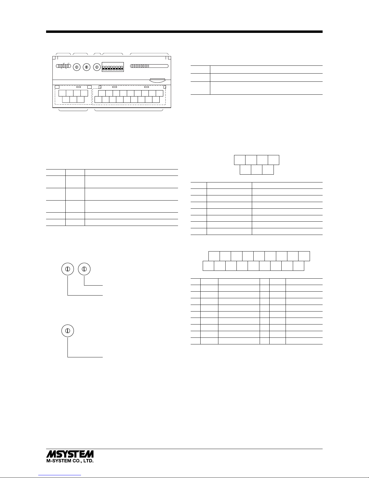
COMPONENT IDENTIFICATION
5
4
3
2
1
0
9
8
7
6
5
4
3
2
1
0
9
8
7
6
5
4
3
2
1
0
9
8
7
6
ERR
RD
RUN SD
PWR
X10 X1
NODE ADD. B.RATE
1 2 3 4 5 6 7 8
0 1 2 3 4 5 6 7 8 9 A B C D E F
4567
123
10 11 12 13
2341
15 16 17 18
7896145
(A) Status Indicator LED
(B) Node Address Setting Rotary SW
(C) Baud Rate Setting Rotary SW
(D) Operating Mode Setting DIP SW (SW1)
(E) Discrete Output Status Indicator LED
(F) Modbus, Power Supply Terminals
(G) Output Terminals
(F) (G)
(B)(A) (C) (D) (E)
■ STATUS INDICATOR LED
ID COLOR FUNCTION
PWR Red
Turns on when the internal 5V is supplied
normally.
RUN Red
Turns on when the data is received normally.
ERR Red
Turns on when the received data is
abnor-
mal. Blinks when setting is abnormal.
SD Red Turns on when the module is transmitting.
RD Red Turns on when the module is receiving.
■ NODE ADDRESS
Node Address is selected between 1 and 99 in decimal. The
left switch determines the tenth place digit, while the right
switch does the ones place digit of the address.
5
4
3
2
1
0
9
8
7
6
5
4
3
2
1
0
9
8
7
6
Node Address Setting (x1)
Factory setting : 00
Node Address Setting (x10)
■ BAUD RATE
Baud Rate is selected with the rotary switch.
5
4
3
2
1
0
9
8
7
6
Baud Rate Setting
0 : 38.4 kbps (factory setting)
1 : 19.2 kbps
2 : 9600 bps
3 : 4800 bps
■ OPERATING MODE
(*) Factory setting
• Output at the Loss of Communication (SW1-4)
SW1-4 OUTPUT AT THE LOSS OF COMMUNICATION
OFF Reset the output (turned off)
ON
Hold the output (*)(maintains the last data received
normally)
Note : Be sure to set unused SW1-1 through 1-3 and 1-5 through
1-8 to OFF.
■ DISCRETE OUTPUT STATUS INDICATOR LED
LED indicators show the signal status.
ON : LED ON
OFF : LED OFF
■ POWER SUPPLY, MODBUS TERMINAL ASSIGNMENT
4DA5DG6
+24V
1DB2
SLD3FG
7
0V
NO. ID FUNCTION, NOTES
1 DB ---2 SLD Shield
3 FG FG
4 DA ---5 DG ---6 +24V Power input (24V DC)
7 0V Power input (0V)
■ OUTPUT TERMINAL ASSIGNMENT
10
+24V11Y012Y1
10V2
COM03COM0
13
Y2
4
COM0
14
Y3
5
COM0
15
Y4
6
COM1
16
Y5
7
COM1
17
Y6
8
COM19COM1
18
Y7
NO.
ID FUNCTION
NO.
ID FUNCTION
1 0V 0V 10 +24V 24V DC
2 COM0 Common 0 11 Y0 Output 0
3 COM0 Common 0 12 Y1 Output 1
4 COM0 Common 0 13 Y2 Output 2
5 COM0 Common 0 14 Y3 Output 3
6 COM1 Common 1 15 Y4 Output 4
7 COM1 Common 1 16 Y5 Output 5
8 COM1 Common 1 17 Y6 Output 6
9 COM1 Common 1 18 Y7 Output 7
Page 3
R7M-DC8C
5-2-55, Minamitsumori, Nishinari-ku, Osaka 557-0063 JAPAN
Phone: +81(6)6659-8201 Fax: +81(6)6659-8510 E-mail: info@m-system.co.jp
EM-7803-U Rev.4 P. 3 / 7
WIRING INSTRUCTIONS
■ SCREW TERMINAL
Torque: 0.5 N·m
■ SOLDERLESS TERMINAL
Refer to the drawing below for recommended ring tongue
terminal size. Spade tongue type is also applicable. Solderless terminal:
Applicable wire size: 0.25 to 1.65 mm
2
(AWG 22 to 16)
Recommended manufacturer: Japan Solderless Terminal
MFG. Co., Ltd, Nichifu Co., Ltd
6 (.24) max
3.3 (.13) max
mm (inch)
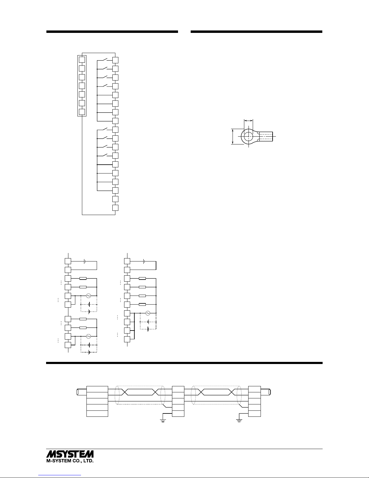
CONNECTION DIAGRAM
Connect the unit as in the diagram below.
4 Points / common
10
14
1
2
5
11
+
24V
Y0
0V
Y3
COM0
COM0
+
–
+
–
18
6
9
15
Y4
Y7
COM1
COM1
+
–
+
–
8 Points / common
10
14
1
2
5
11
+
24V
24V DC
Y0
0V
+
–
Y3
15
Y4
18
Y7
COM0
COM0
6
9
COM1
COM1
+
–
+
–
24V DC
+
–
5
2
6
4
7
13
8
9
14
12
15
11
16
17
18
COM0
COM0
COM0
Y0
Y1
Y2
Y3
COM0
COM1
COM1
COM1
Y4
Y5
Y6
Y7
COM1
3
4
1
2
5
3
FG
6
7
24 V DC
0 V
SLD
DG
DB
DA
10
1
0 V
+
24 V
■ Output Connection Example
In order to improve EMC performance, bond the FG
terminal to ground.
Caution: FG terminal is NOT a protective conductor terminal.
MASTER CONNECTION
■ MASTER CONNECTION
Tx+/Rx+
Tx–/Rx–
SG
Rx+
Rx–
Host PC
DA
DB
DG
SLD
FG
Remote Unit
DA
DB
DG
SLD
FG
Remote Unit
TERMINATOR TERMINATOR
Be sure to connect the terminating resistor included in the product package to the unit at both ends of transmission line.
The terminator must be connected across DA and DB.
The Host PC can be located other than at the extreme ends of transmission line.
Page 4

R7M-DC8C
5-2-55, Minamitsumori, Nishinari-ku, Osaka 557-0063 JAPAN
Phone: +81(6)6659-8201 Fax: +81(6)6659-8510 E-mail: info@m-system.co.jp
EM-7803-U Rev.4 P. 4 / 7
EXTERNAL DIMENSIONS unit: mm (inch)
4567
123
10 11 12 13
2341
15 16 17 18
78
9
6145
30 (1.18)
[5 (.20)]
3 (.12)5.5 (.22)
DIN RAIL
35mm wide
54 (2.13)
17 (.66)
50 (1.97)
18.5 (.73)
115 (4.53)
7–M3 SCREW
TERMINALS
for Modbus, POWER
18–M3 SCREW
TERMINALS
for OUTPUT
6 (.24)
6 (.24)
CONFORMITY WITH CE MARKING
■ CE MARKING
CE marking requires to integrate safety regulations existed in each country in EU territory and to secure smooth distribution
of products of which safety is guaranteed. It is mandatory by law that products distributed and sold in EU territory to have
CE mark which shows that the product conforms with the requirements of EU Directive. Each EU Directive describes the
scope of apparatuses to which that EU Directive is applied. M-System’s R7M must conform with EMC Directive.
Each Directive states only basic requirements. In order to mark the CE on an assembled machinery equipment, its manufacturer needs to check the overall conformity with Directives applicable to it.
■ WARNINGS AND CAUTIONS WHEN INSTALLING THE R7M
The R7M needs to be installed in a control panel. This is effective not only to ensure general safety but also to contain noise
emissions by the R7M inside the control panel. We conduct a series of testing to see that the product conforms to EMC Directive while it is installed in the control panel.
Warning and cautions when installing R7M are stated below.
•Use control panels with an internal panel plate, both made of metal, when installing the R7M.
•Make sure to adequately ground the control panel and the internal panel plate with a thick cable to maintain low imped-
ance at high frequency.
•Use shielded cables for the signals taken out of the control panel.
•Choose a thick and short cable to ground the FG terminal of the R7M module to the internal panel plate of the control panel.
•Note: If electromagnetic radiation disturbance increases by grounding the FG terminal, remove the grounding.
•When painting the internal plate of the control panel, apply masking to expose metal surface to secure conductivity at the
sections where the following parts are attached:
- Bolts attaching the internal panel to the control panel
- Ground for the FG of the R7M module
- Earth clamp on the shielded cable
•Noise emissions inside the control panel might leak through its openings. Design them as small as possible. Recommended
diameter is 10 cm or less.
Supplement:
Additional measures may be taken depending upon actual installation sites. These points of cautions are illustrated in the
next page.
•Prevent noise leakage by wrapping cables using shield covers, shield tubes and flexible conduits etc. if noise leaks through
the cable outlet.
•Use an electromagnetic shield gasket and block up the gap between the control panel cabinet and its cover, if noise leaks
through it.
•Connecting the internal panel plate and the cover of the control panel to the main cabinet using an earth strap may be
effective to strengthen the grounding.
•Electromagnetically shielded control panel cabinet is effective for shielding.
Page 5

R7M-DC8C
5-2-55, Minamitsumori, Nishinari-ku, Osaka 557-0063 JAPAN
Phone: +81(6)6659-8201 Fax: +81(6)6659-8510 E-mail: info@m-system.co.jp
EM-7803-U Rev.4 P. 5 / 7
Use (e.g.) a shield cover
when noise leaks through
the opening.
To external apparatus
Keep the opening
for cabling as small as
possible.
Install an electromagnetically
shielded gasket when
noise leaks through
the opening.
Shielding is strengthened
by using an electromagnetically shielded
control panel.
By connecting the
internal panel plate
and the panel cover with
an earth strap, grounding
may be strengthened and
EMC may be improved.
Ground the control panel
at low impedance using
(e.g.) braided wires.
Keep the opening for
ventilation as small as
posible.
Attach an electromagnetically shielded
filter when noise leaks
through the opening.
Install the R7M Series inside
a control panel.
Attachment part of earth
clamp should be fixed with
screw in conduction with the
internal panel plate.
• Points of cautions applicable when installing the R7M Series
Page 6

R7M-DC8C
5-2-55, Minamitsumori, Nishinari-ku, Osaka 557-0063 JAPAN
Phone: +81(6)6659-8201 Fax: +81(6)6659-8510 E-mail: info@m-system.co.jp
EM-7803-U Rev.4 P. 6 / 7
■ WARNINGS AND CAUTIONS WHEN LAYING CABLES
Signal cables connected to the R7M contain high-frequency components. Since these cables has the same effect as an antenna, they emit these high-frequency components to the external space as noise or overlaps noise from the external space
on themselves.
Cables with shielding should be used for the signal line due to the above reason.
EMC conformance test is conducted in the condition that shielded cables and earth clamps are used with the R7M.
Warning and cautions when laying cables are stated below. These points of cautions are illustrated in the next page.
•Use shielded cables for those signal cables installed out of the control panel and for thermocouple and RTD extension wires.
•All the network cables connected to R7M should be shielded.
•Use shielded cables for network communication.
•Expose the shield at a part of the cable cover, clip it with an earth clamp, and ground it to the internal panel of the control
panel. A drain wire connected to the panel in a pig-tail form cannot maintain low impedance against high-frequency noise,
thus grounding (noise shielding) in this form will not be effective.
Supplement:
Additional measures may be taken depending upon actual installation sites. These points of cautions are illustrated in the
next page.
•Keep cables as short as possible. It prevents noise emissions from the cables and noise overlapping to the cables.
•Attach a ferrite core to reduce noise impact to the signal cables susceptible to the noise. Ferrite core can be attached close
to the cable outlet of the control panel or close to the I/O terminal or connector, whichever is more effective. Also, the impact
might be reduced by winding the cable around the ferrite core for extra turns or attaching multiple ferrite cores.
•Keep cables which are easily affected by noise away from those which can be a noise source.
•Keeping physical distance (farther than 20 cm from motor drive cables, farther than 10 cm for other groups).
Motor Drive
Cable
Power Supply
Cable
DC Signal Cable
Network Cable
Analog Signal
Cable
Often being a noise source Often subject to noise interference.
In the following are examples of effective ways to lay cables separately:
•Dividing off by a grounded metal plate
•Grouping into separate grounded metal pipes or cable shields.
Wires on each side of a filter should not be too close to each other. Noise could ride onto the other side of cable.
Extra attention needs to be paid at the following parts.
•Noise filter that is enclosed in power cables.
•Ferrite core that is attached to signal cables.
•Noise limiting circuit (surge quenching circuit, transient absorber circuit, etc.) that is enclosed in signal cables.
Page 7

R7M-DC8C
5-2-55, Minamitsumori, Nishinari-ku, Osaka 557-0063 JAPAN
Phone: +81(6)6659-8201 Fax: +81(6)6659-8510 E-mail: info@m-system.co.jp
EM-7803-U Rev.4 P. 7 / 7
Noise
Filter
Motor
Drive Cable
Maintain distance between
cables and noise sources.
Grounding in pig tail form
is not effective.
• Points of cautions applicable when wiring the R7M Series
To external apparatus
Keep the cable as
short as possible.
To external apparatus
Shielded
Cable
Earth
Clamp
Remove a part of the shielded
cable cover and ground it
to the internal panel
plate using an earth
clamp.
To connect with
apparatuses outside
the control panel via
Modbus, ground the
cable shield using
an earth clamp.
Keep the wires away from
each other at both ends of
the filter.
 Loading...