

Page 1

INSTRUCTION MANUAL
NPN TRANSISTOR OUTPUT MODULE, 16 points
(LONWORKS)
BEFORE USE ....
Thank you for choosing M-System. Before use, please check
contents of the package you received as outlined below.
If you have any problems or questions with the product,
please contact M-System’s Sales Office or representatives.
■ PACKAGE INCLUDES:
Transistor output module ..................................................(1)
NeuronID label ...................................................................(2)
■ MODEL NO.
Confirm Model No. marking on the product is exactly what
you ordered.
■ INSTRUCTION MANUAL
This manual describes necessary points of caution when
you use this product, including installation, connection and
basic maintenance procedures.
LNS Plug-in Software (model: R7LPLG) is usable to set up
Functional Blocks. For detailed information, refer to the
R7PLG Users Manual. The R7LPLG is downloadable at
M-System’s web site: http://www.m-system.co.jp
POINTS OF CAUTION
■ POWER INPUT RATING & OPERATIONAL RANGE
• Locate the power input rating marked on the product and
confirm its operational range as indicated below:
24V AC rating: 24V ±10%, 50/60 Hz, approx. 80mA
24V DC rating: 24V ±10%, approx. 50mA
■ GENERAL PRECAUTIONS
• Before you remove the unit or mount it, turn off the power
supply and output signal for safety.
■ ENVIRONMENT
• Indoor use.
• When heavy dust or metal particles are present in the
air, install the unit inside proper housing with sufficient
ventilation.
• Do not install the unit where it is subjected to continuous
vibration. Do not subject the unit to physical impact.
• Environmental temperature must be within -10 to +55°C
(14 to 131°F) with relative humidity within 30 to 90% RH
in order to ensure adequate life span and operation.
■ WIRING
• Do not install cables close to noise sources (relay drive
cable, high frequency line, etc.).
• Do not bind these cables together with those in which
noises are present. Do not install them in the same duct.
MODEL
R7L-DC16A
■ RESTRICTIONS WHEN USING LonMaker3.0 or 3.1
• Operating Environment
Please use LonMaker3.0 under the Environment of LNS3
Service Pack 8 and use LonMaker3.1 under the Environment of LonMaker3.1 Service Pack 3 or later.
Please use resource files of LonMark Resource File Ver12
or later.
• LNS Plug-in Software is not usable.
• The network variable of nvoCNTOut (fbCNT) is only
SNVT_count_f.
• When registering a Device on LonMaker, please don’t use
the following items.
External Interface Definition / Upload From Device
Specify Device Channel / Auto-Detect
■ AND ....
• The unit is designed to function as soon as power is supplied, however, a warm up for 10 minutes is required for
satisfying complete performance described in the data
sheet.
5-2-55, Minamitsumori, Nishinari-ku, Osaka 557-0063 JAPAN
Phone: +81(6)6659-8201 Fax: +81(6)6659-8510 E-mail: info@m-system.co.jp
EM-7804-G Rev.7 P. 1 / 19
Page 2
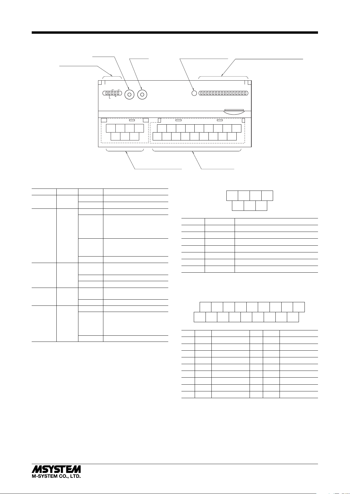
COMPONENT IDENTIFICATION
R7L-DC16A
Service SW
Status Indicator LED
PWR
ONLINE
Reset SW Factory Configuration Port
ERR
SVCE
TX/RX
4567
123
■ STATUS INDICATOR LED
ID COLOR STAT E MEANING
PWR Green
ON Internal 5V is normal
OFF Internal 5V is abnormal.
ON Online
Offline
Sending/receiving of Network
Variables has stopped.
ONLINE Green
Blink
approx.
0.5 Hz
Blink
approx.
Receiving Wink Message
2 Hz
OFF Abnormal state
Writing in the non-volatile
memory
ERR Red
ON
Blink Abnormal state
OFF Normal state
Sending/receiving Network
Variables
TX/RX Green
ON
OFF Communication is lost.
ON No network information
Offline
Sending/receiving of Net-
work
Variables has stopped.
SVCE Green
Blink
approx.
0.5 Hz
OFF Normal state
■ DISCRETE OUTPUT STATUS INDICATOR LED
Used to show discrete output signal status.
ON : LED ON
OFF : LED OFF
■ SERVICE SWITCH
Used to identify the node in L
ONWORKS network configura-
tion.
10 11 12 13
2341
L
ONWORKS, Power Supply
Terminals
Discrete Output Status Indicator LED
0 1 2 3 4 5 6 7 8 9 A B C D E F
15 16 17 18
14
5
■ POWER SUPPLY, L
7896
Output Terminals
4
NET15NET26U (+)
ONWORKS TERMINAL ASSIGNMENT
7
–
)
1
NET12NET23FG
V (
NO. ID FUNCTION, NOTES
1 NET1 L
2 NET2 L
ONWORKS communication 1
ONWORKS communication 2
3 FG FG
4 NET1 L
5 NET2 L
ONWORKS communication 1
ONWORKS communication 2
6 U (+) Power input
7 V (–) Power input
ONWORKS wiring must be paired between NET1 termi-
Note: L
nals and/or NET2 terminals.
■ OUTPUT TERMINAL ASSIGNMENT
10
+24V11Y112Y3
10V2Y03
Y2
13
14
15
16
17
Y5
Y7
Y9
4
5
Y4
6
Y6
Y8
YB
7
YA
18
YD
8YC9
YE
NO. ID FUNCTION NO. ID FUNCTION
1 0V 0V (common) 10 +24V 24V DC
2 Y0 Output 0 11 Y1 Output 1
3 Y2 Output 2 12 Y3 Output 3
4 Y4 Output 4 13 Y5 Output 5
5 Y6 Output 6 14 Y7 Output 7
6 Y8 Output 8 15 Y9 Output 9
7 YA Output 10 16 YB Output 11
8 YC Output 12 17 YD Output 13
9 YE Output 14 18 YF Output 15
YF
■ RESET SWITCH
Used to reset the Neuron Chip. Press the switch behind the
front cover to reset.
Control functions are halted while completing resetting and
restarting. Confirm no danger before conducting resetting.
5-2-55, Minamitsumori, Nishinari-ku, Osaka 557-0063 JAPAN
Phone: +81(6)6659-8201 Fax: +81(6)6659-8510 E-mail: info@m-system.co.jp
EM-7804-G Rev.7 P. 2 / 19
Page 3
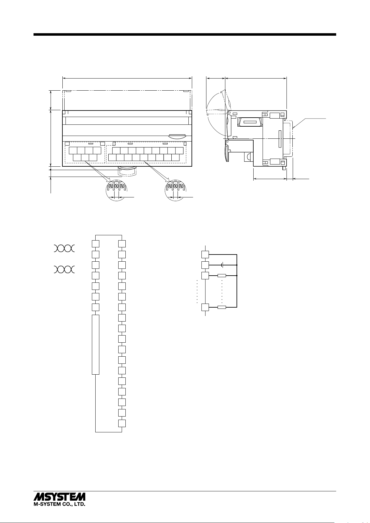
TERMINAL CONNECTIONS
Connect the unit as in the diagram below.
■ EXTERNAL DIMENSIONS unit: mm (inch)
115 (4.53)
17 (.66)
R7L-DC16A
54 (2.13)
18.5 (.73)
50 (1.97)
4567
123
3 (.12)5.5 (.22)
■ CONNECTION DIAGRAM
LONWORKS
LONWORKS
NET1
NET1
NET2
NET2
FG
U (+)
V (–)
4
1
5
2
3
6
7
10 11 12 13
2341
6 (.24)
7–M3 SCREW
TERMINALS
for LONWORKS, POWER
10
+24V
2
Y0
3
Y2
4
Y4
5
Y6
6
Y8
7
YA
8
YC
9
YE
11
Y1
12
Y3
13
Y5
EXTENSION CONNECTOR
14
15
16
17
18
Y7
Y9
YB
YD
YF
1
0V
15 16 17 18
9
78
6145
6 (.24)
18–M3 SCREW
TERMINALS for OUTPUT
■ Output Connection Example
10
+24V
1
0V
2
Y0
18
YF
DIN RAIL
35mm wide
30 (1.18)
+
–
[5 (.20)]
5-2-55, Minamitsumori, Nishinari-ku, Osaka 557-0063 JAPAN
Phone: +81(6)6659-8201 Fax: +81(6)6659-8510 E-mail: info@m-system.co.jp
EM-7804-G Rev.7 P. 3 / 19
Page 4
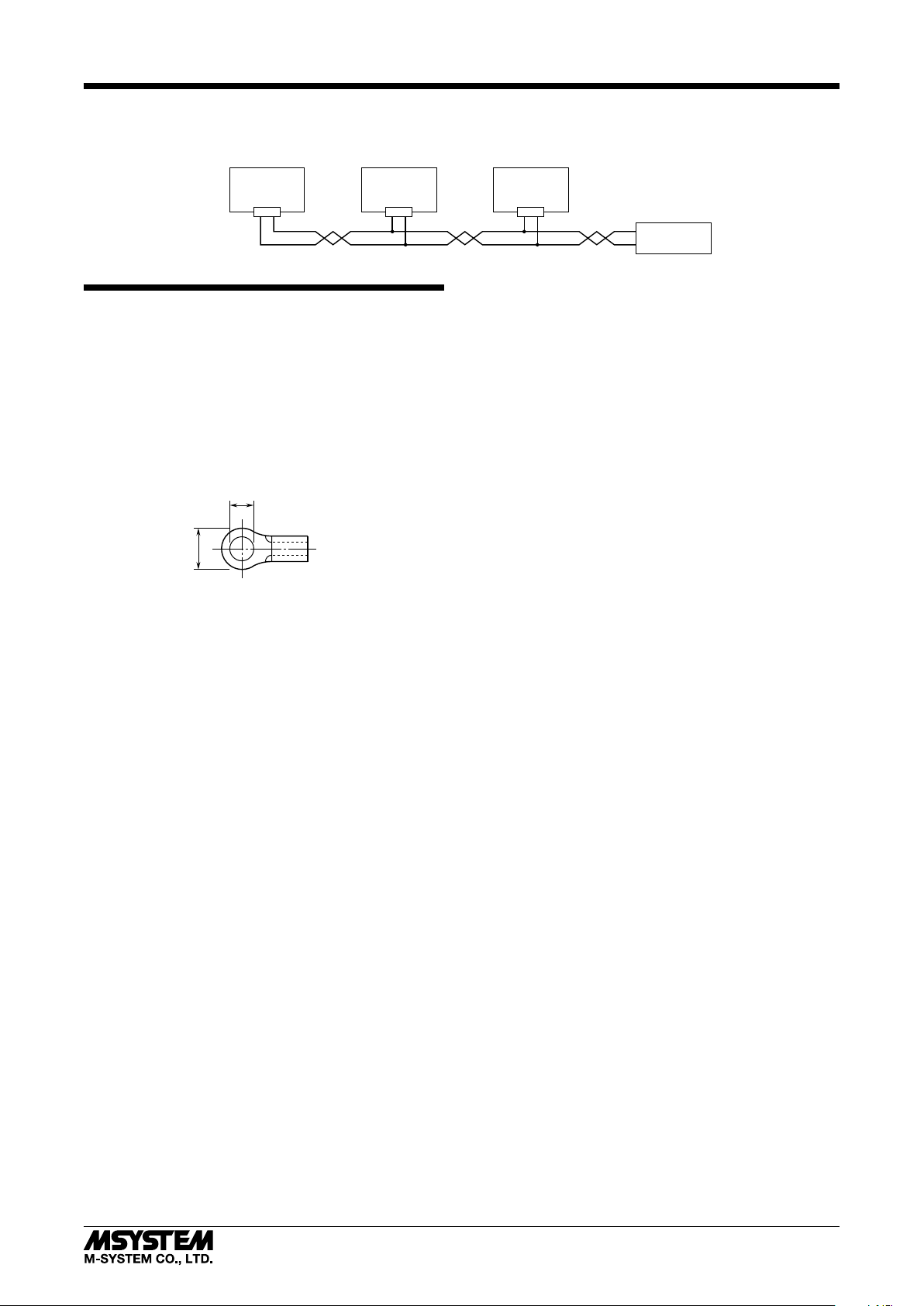
COMMUNICATION CABLE CONNECTIONS
■ HOST PC CONNECTION
HOST PC
R7L
R7L-DC16A
R7L
LONWORKS
LONWORKS
WIRING INSTRUCTIONS
■ SCREW TERMINAL
Torque: 0.5 N·m
■ SOLDERLESS TERMINAL
Refer to the drawing below for recommended ring tongue
terminal size. Spade tongue type is also applicable.
Applicable wire size: 0.25 to 1.65 mm
Recommended manufacturer: Japan Solderless Terminal
MFG. Co., Ltd, Nichifu Co., Ltd
3.3 (.13) max
6 (.24) max
2
(AWG 22 to 16)
mm (inch)
LONWORKS
Terminator
5-2-55, Minamitsumori, Nishinari-ku, Osaka 557-0063 JAPAN
Phone: +81(6)6659-8201 Fax: +81(6)6659-8510 E-mail: info@m-system.co.jp
EM-7804-G Rev.7 P. 4 / 19
Page 5

DEVICE INTERFACE FILE
Device Interface File (XIF) is used to define a LONWORKS device when programmed on LonMaker.
For this module, the following file is used:
R7L-DC16v113.XIF
The XIF files are downloadable at M-System’s web site: http://www.m-system.co.jp
FUNCTIONAL BLOCKS
■ NodeObject
NodeObject (Object ID : 0)
Network Variables
R7L-DC16A
nviRequest
nv 0
SNVT_obj_request
NodeObject :
SCPTdirection
SCPTmaxSendTime[ ]
SCPTminSendTime[ ]
SCPTlocation
SCPToemType
SCPTserialNumber
Configuration Properties
Extension module setting
Maximum sending time (per fb)
Minimum sending time (per fb)
Set Tag No. (name)
Indicate Model No. and Version
Indicate Serial No.
nv 1
nv 2
nv 3
• Network Variables
NETWORK
VARIABLE
TYPE
{ Range }
{ Default }
EXPLANATIONS
nviRequest {SNVT_obj_request} For use with LonMaker and other tools.
nvoStatus {SNVT_obj_status} For use with LonMaker and other tools.
nvoFileDirectory {SNVT_address}
For use with LonMaker and other tools.
Required to get access to Configuration Properties.
Shows the device status (All 0s in normal conditions).
nvoABNLCond {SNVT_state}
Bit 0 through Bit 9 : Invalid
Bit 10 : E
Bit 11 : E2PROM Count data check sum error
2
PROM Configuration Property check sum error
(Bit 10 and Bit 11 can be reset to 0 by RQ_CLEAR_STATUS against NodeObject.)
Bit 12 through Bit 15 : Invalid
nvoStatus
SNVT_obj_status
nvoFileDirectory
SNVT_address
nvoABNLCond
SNVT_state
5-2-55, Minamitsumori, Nishinari-ku, Osaka 557-0063 JAPAN
Phone: +81(6)6659-8201 Fax: +81(6)6659-8510 E-mail: info@m-system.co.jp
EM-7804-G Rev.7 P. 5 / 19
Page 6

• Conguration Properties
CONFIGURATION
PROPERTY
SCPTdirection ----
SCPTmaxSendTime
[Number of fb]
SCPTminSendTime
[Number of fb]
SCPTlocation ----
SCPToemType ----
SCPTserialNumber ----
NETWORK
VARIABLE
----
----
TYPE
{ Range }
{ Default }
{SNVT_state}
{0 or 1}
{0,0,0,0,0,0,0,0,
0,0,0,0,0,0,0,0}
{SNVT_time_sec}
{0.0,10.0...3600.0}
{0.0}
{SNVT_time_sec}
{0.0,0.2...3600.0}
{1.0}
{SNVT_str_asc}
{30-character string}
{“”}
{SNVT_str_asc}
e.g. “R7L-DC16A_VER:0.10”
{
{SNVT_str_asc}
{e.g. “ZZ123456”}
R7L-DC16A
EXPLANATIONS
Bit 0, Bit 1: Setting the extension module (Power supply
must be reset when this configuration property is changed.)
0,0 : Without extension module
1,0 : Discrete input (fb and other settings assigned to the 9th
and following points are invalid with 8-point input module.)
0,1 : Discrete output (fb and other settings assigned to the
9th and following points are invalid with 8-point output
module.)
Set this property before an extension module is connected.
Bit 2 through Bit 15 : Invalid
Maximum time interval to send network variables (per fb).
(Power supply must be reset when this configuration property is changed.)
Network variables are sent out in the specified intervals
even when there is no change in the value.
No sending when a value less than 10.0 is set.
Invalid property when the assigned fb has no network variables to be sent to the network.
Minimum time interval to send network variables (per fb).
(Power supply must be reset when this configuration property is changed.)
Network variables are sent out in the specified intervals
even when there are changes in the value faster than the
interval.
No sending when a value less than 0.2 is set.
Invalid property when the assigned fb has no network variables to be sent to the network.
Used to write Tag No. (name)
Used to indicate Model No. and Version
}
Used to indicate Serial No.
5-2-55, Minamitsumori, Nishinari-ku, Osaka 557-0063 JAPAN
Phone: +81(6)6659-8201 Fax: +81(6)6659-8510 E-mail: info@m-system.co.jp
EM-7804-G Rev.7 P. 6 / 19
Page 7

■ FUNCTIONAL BLOCK: fbCNT[0...7]
R7L-DC16A
fbCNT[0...7] (Object ID : 17...24)
Network Variables
• Network Variables
NETWORK
VARIABLE
TYPE
{ Range }
{ Default }
{SNVT_switch}
nviCNTIn
{0.0 0}, {100.0 1}, {Invalid}
{0.0 0}
{SNVT_switch}
nviCNTCtrl
{0.0 0}, {100.0 1}, {Invalid}
{0.0 0}
{SNVT_count_32}
{0...999 999 999}
nvoCNTOut
{0}
{SNVT_count_f}
{0...999 999}
{0}
nviCNTIn
nv 36
...nv 43
...nv 51
SNVT_switch
nviCNTCtrl
nv 44
SNVT_switch
fbCNT[ ] :
SCPTdirection
nviCNTIn :
SCPTinvrtOut
nviCNTCtrl :
SCPTpwrUpState
nvoCNTOut :
SCPTnvType
SCPTmaxRnge
SCPTsetpoint
nvoCNTOut
nv 52
...nv 59
Configuration Properties
Set operating mode
Set count logic (ON or OFF)
Set the initial value at nviCNTCtrl at the startup
Set network variable type nvoCNTOut
Set the maximum count
Set the value when fbCNT[ ] is reset
SNVT_count_32
SNVT_count_f
EXPLANATIONS
Counted object
Controls operation of fbCNT
0.0 0 : Stop counting
100.0 1 : Start counting
Invalid : Reset count value
Number of ON counts or accumulated time of ON status at nviCNTIn or
the input terminal
5-2-55, Minamitsumori, Nishinari-ku, Osaka 557-0063 JAPAN
Phone: +81(6)6659-8201 Fax: +81(6)6659-8510 E-mail: info@m-system.co.jp
EM-7804-G Rev.7 P. 7 / 19
Page 8

• Conguration Properties
CONFIGURATION
PROPERTY
SCPTdirection ----
SCPTinvrtOut nviCNTIn
SCPTpwrUpState nviCNTCtrl
SCPTnvType nvoCNTOut
SCPTmaxRnge nvoCNTOut
SCPTsetpoint nvoCNTOut
NETWORK
VARIABLE
TYPE
{ Range }
{ Default }
{SNVT_state}
{0 or 1}
{0,0,0,0,0,0,0,0,
0,0,0,0,0,0,0,0}
{SNVT_lev_disc}
{ST_OFF, ST_ON}
{ST_OFF}
{SNVT_switch}
{0.0 0}, {100.0 1}, {Invalid}
{100.0 1}
{SNVT_nv_type}
{}
{SNVT_count_f}
Same as nvoCNTOut.
Default = Max. range value
available for the type
Same as nvoCNTOut.
Default = Max. range value
available for the type
R7L-DC16A
EXPLANATIONS
Bit 0 through 4: Counted object
0,0,0,0,0 : nviCNTIn
1,0,0,0,0 : ExX0
0,1,0,0,0 : ExX1
1,1,0,0,0 : ExX2
0,0,1,0,0 : ExX3
1,0,1,0,0 : ExX4
0,1,1,0,0 : ExX5
1,1,1,0,0 : ExX6
0,0,0,1,0 : ExX7
1,0,0,1,0 : ExX8
0,1,0,1,0 : ExX9
1,1,0,1,0 : ExXA
0,0,1,1,0 : ExXB
1,0,1,1,0 : ExXC
0,1,1,1,0 : ExXD
1,1,1,1,0 : ExXE
0,0,0,0,1 : ExXF
ExX0 through ExXF: Extension discrete input
Bit 6: Count function
0 : Number of status changes from OFF to ON
1 : Accumulated time of ON status
Bit 7: Memory storage at the non-volatile memory
0 : Count retained in the memory and preset at the startup
1 : Count always reset to 0
Bit 5, 8 through 15 : Invalid
Minimum input pulse width 500 ms for nviCNTIn, 50 ms
for the input terminals.
DO NOT connect a network variable to nviCNTIn when one
of the input terminals (other than nviCNTIn) is assigned as
the counted object.
ON time per 1 second increments.
Count logic at nviCNTIn.
ST_OFF : Count with nvoCNTIn = ON
ST_ON : Count with nvoCNTIn = OFF
Set value applied at nviCNTCtrl when the power supply is
turned on.
0.0 0 : Stop counting
100.0 1 : Start counting
Invalid : Reset count value
Indicates nvoCNTOut type.
For use with LonMaker and other tools.
Maximum count for nvoCNTOut. Count reset to 0 and
restarted at overflow.
Set value applied at nvoCNTOut when fbCNT[ ] is OverRide.
5-2-55, Minamitsumori, Nishinari-ku, Osaka 557-0063 JAPAN
Phone: +81(6)6659-8201 Fax: +81(6)6659-8510 E-mail: info@m-system.co.jp
EM-7804-G Rev.7 P. 8 / 19
Page 9

■ FUNCTIONAL BLOCK: fbDO[0...7]
R7L-DC16A
fbDO [0...7] (Object ID : 25...32)
Network Variables
nv 60
...nv 67
nv 68
...nv 75
Discrete output Y0, Y2, Y4, Y6,
State Mode Output nviDO status Output nviDOOvr status
Momentary Mode 1 or 2 One-shot output at ON
nviDO
SNVT_switch
nviDOOvr
SNVT_switch
Configuration Properties
fbDO [ ] :
SCPTdirection
SCPTtimeout
Y8, YA, YC, YE
(nviDO or nviDOOvr at ON)
nv 76
...nv 83
Set operating mode
Pulse output ON time in Momentary Mode
nvoDOStat
SNVT_switch
Y1, Y3, Y5, Y7,
Y9, YB, YD, YF
One-shot output at OFF
(nviDO or nviDOOvr at OFF)
• Output Terminal v.s. fbDO Network Variables (nviDO, nviDOOvr) Assignments
FUNCTIONAL BLOCK NETWORK VARIABLE OUTPUT TERMINAL
fbDO[0]
fbDO[1]
fbDO[2]
fbDO[3]
fbDO[4]
fbDO[5]
fbDO[6]
fbDO[7]
nviDO Y0
nviDOOvr Y1
nviDO Y2
nviDOOvr Y3
nviDO Y4
nviDOOvr Y5
nviDO Y6
nviDOOvr Y7
nviDO Y8
nviDOOvr Y9
nviDO YA
nviDOOvr YB
nviDO YC
nviDOOvr YD
nviDO YE
nviDOOvr YF
5-2-55, Minamitsumori, Nishinari-ku, Osaka 557-0063 JAPAN
Phone: +81(6)6659-8201 Fax: +81(6)6659-8510 E-mail: info@m-system.co.jp
EM-7804-G Rev.7 P. 9 / 19
Page 10

■ FUNCTIONAL BLOCK: fbDO[0...7]
• Network Properties
State Mode
NETWORK
VARIABLE
nviDO
nviDOOvr
nvoDOStat
TYPE
{ Range }
{ Default }
{SNVT_switch}
{0.0 0}, {100.0 1}, {Invalid}
{0.0 0}
{SNVT_switch}
{0.0 0}, {100.0 1}, {Invalid}
{0.0 0}
{SNVT_switch}
{0.0 0}, {100.0 1}, {Invalid}
{0.0 0}
Momentary Mode 1 or 2
NETWORK
VARIABLE
nviDO
nviDOOvr
nvoDOStat
TYPE
{ Range }
{ Default }
{SNVT_switch}
{0.0 0}, {100.0 1}, {Invalid}
{0.0 0}
{SNVT_switch}
{0.0 0}, {100.0 1}, {Invalid}
{0.0 0}
{SNVT_switch}
{0.0 0}, {100.0 1}, {Invalid}
{0.0 0}
R7L-DC16A
EXPLANATIONS
Turns on or off Y0, Y2, Y4, Y6, Y8, YA, YC, YE depending upon this input.
Turns on or off Y1, Y3, Y5, Y7, Y9, YB, YD, YF depending upon this input.
Invalid
EXPLANATIONS
Y0, Y2, Y4, Y6, Y8, YA, YC, YE : One-shot output when the input is ON.
Y1, Y3, Y5, Y7, Y9, YB, YD, YF : One-shot output when the input is OFF.
nviDO status is invalid when nviDOOvr is other than ‘Invalid.’ One-shot
output is provided at either Y0 or Y1 depending upon nviDOOvr value.
Outputs last one-shot output status.
• Conguration Properties
Common
CONFIGURATION
PROPERTY
SCPTdirection ----
NETWORK
VARIABLE
TYPE
{ Range }
{ Default }
{SNVT_state}
{0 or 1}
{0,0,0,0,0,0,0,0,
0,0,0,0,0,0,0,0}
Momentary Mode 1 or 2
CONFIGURATION
PROPERTY
SCPTtimeout ----
NETWORK
VARIABLE
TYPE
{ Range }
{ Default }
{SNVT_time_sec}
{0.1...60.0}
{0.5}
• Difference between Momentary Mode 1 and 2
nviDO or nviDOOvr
Momentary Mode 1
Y0, Y2, Y4 and Y6
Y1, Y3, Y5 and Y7
ON
EXPLANATIONS
Bit 0 and 2: fbDO operating mode
0 and 0: State mode
1 and 0: Momentary mode 1
1 and 1: Momentary mode 2
Bit 1: Output held or not at power off in State mode
0 : OFF at the power startup
1 : Outputs the held status at the power startup
Bit 3 through 15 : Invalid
EXPLANATIONS
Specifies ON time for the one-shot output
OFF ON ON OFF OFF
Momentary Mode 2
Y0, Y2, Y4 and Y6
Y1, Y3, Y5 and Y7
5-2-55, Minamitsumori, Nishinari-ku, Osaka 557-0063 JAPAN
Phone: +81(6)6659-8201 Fax: +81(6)6659-8510 E-mail: info@m-system.co.jp
EM-7804-G Rev.7 P. 10 / 19
Page 11

■ FUNCTIONAL BLOCK: fbCMP[0...7]
R7L-DC16A
fbCMP[0...7] (Object ID : 33...40)
Network Variables
• Network Variables
NETWORK
VARIABLE
nviCMPIn1
nviCMPIn2
nvoCMPOut
TYPE
{ Range }
{ Default }
{SNVT_switch}
{0.0 0}, {100.0 1}, {Invalid}
{0.0 0}
{SNVT_switch}
{0.0 0}, {100.0 1}, {Invalid}
{0.0 0}
{SNVT_switch}
{0.0 0}, {100.0 1}, {Invalid}
{0.0 0}
nv 84
...nv 91
nv 92
...nv 99
nviCMPIn1
SNVT_switch
nviCMPIn2
SNVT_switch
fbCMP[ ] :
SCPTtimeout
nv 100
...nv 107
Configuration Properties
Delay time before the nvoCMPOut when the
nviCMPIn1 and nviCMPIn2 are deviated.
EXPLANATIONS
Connects to the network variable to be compared.
Connects to the network variable to be compared.
nviCMPIn1 and nviCMPIn2 are compared. OFF is output when both values are equivalent, ON or ‘Invalid’ is output when they are not.
ON is output when nviCMPIn1 status change caused the discrepancy.
‘Invalid’ is output when nviCMPIn2 status change caused it.
OFF is output when nviCMPIn1 and/or nviCMPIn2 is ‘Invalid,’ regardless
of the values of both.
nvoCMPOut
SNVT_switch
• Conguration Properties
CONFIGURATION
PROPERTY
SCPTtimeout ----
NETWORK
VARIABLE
TYPE
{ Range }
{ Default }
{SNVT_time_sec}
{0.1...60.0}
{5.0}
EXPLANATIONS
Delay time before ON or ‘Invalid’ is output when a discrepancy occurs between nviCMPIn1 and nviCMPIn2.
OFF is immediately output when nviCMPIn1 and nviCMPIn2 states match, regardless of this setting.
5-2-55, Minamitsumori, Nishinari-ku, Osaka 557-0063 JAPAN
Phone: +81(6)6659-8201 Fax: +81(6)6659-8510 E-mail: info@m-system.co.jp
EM-7804-G Rev.7 P. 11 / 19
Page 12

■ FUNCTIONAL BLOCK: fbEN[0...3]
R7L-DC16A
fbEN[0...3] (Object ID : 41...44)
Network Variables
• Network Variables
NETWORK
VARIABLE
nviENIn1
nviENIn2
nviENIn3
nviENIn4
nvoENOut
TYPE
{ Range }
{ Default }
{SNVT_switch}
{0.0 0}, {100.0 1}, {Invalid}
{0.0 0}
{SNVT_switch}
{0.0 0}, {100.0 1}, {Invalid}
{0.0 0}
{SNVT_switch}
{0.0 0}, {100.0 1}, {Invalid}
{0.0 0}
{SNVT_switch}
{0.0 0}, {100.0 1}, {Invalid}
{0.0 0}
{SNVT_switch}
{0.0 0}, {100.0 1}, {Invalid}
{0.0 0}
nv 108
...nv 111
nv 112
...nv 115
nv 116
...nv 119
nv 120
...nv 123
nviENIn1
SNVT_switch
nviENIn2
SNVT_switch
nviENIn3
SNVT_switch
nviENIn4
SNVT_switch
Configuration Properties
fbEN[ ] :
SCPTvalueDefinition[0...16] Set value table at nvoENOut
EXPLANATIONS
Encoder input 1
Encoder input 2
Encoder input 3
Encoder input 4
Outputs the SCPTvalueDefinition[ ] value according to the input signal
status
nv 124
...nv 127
for nviENIn1...4
nvoENOut
SNVT_switch
5-2-55, Minamitsumori, Nishinari-ku, Osaka 557-0063 JAPAN
Phone: +81(6)6659-8201 Fax: +81(6)6659-8510 E-mail: info@m-system.co.jp
EM-7804-G Rev.7 P. 12 / 19
Page 13

• Conguration Properties
CONFIGURATION
PROPERTY
SCPTvalueDefinition[0...16] ----
NETWORK
VARIABLE
TYPE
{ Range }
{ Default }
{SNVT_switch}
{0.0 0}, {100.0 1}, {Invalid}
{0.0 0}
• Input v.s. SCPTvalueDenition
nviENIn1 nviENIn2 nviENIn3 nviENIn4 nvoENOut VALUE
OFF OFF OFF OFF SCPTvalueDefinition[0]
ON OFF OFF OFF SCPTvalueDefinition[1]
OFF ON OFF OFF SCPTvalueDefinition[2]
ON ON OFF OFF SCPTvalueDefinition[3]
OFF OFF ON OFF SCPTvalueDefinition[4]
ON OFF ON OFF SCPTvalueDefinition[5]
OFF ON ON OFF SCPTvalueDefinition[6]
ON ON ON OFF SCPTvalueDefinition[7]
OFF OFF OFF ON SCPTvalueDefinition[8]
ON OFF OFF ON SCPTvalueDefinition[9]
ON ON OFF ON SCPTvalueDefinition[10]
OFF ON OFF ON SCPTvalueDefinition[11]
ON OFF ON ON SCPTvalueDefinition[12]
OFF OFF ON ON SCPTvalueDefinition[13]
ON ON ON ON SCPTvalueDefinition[14]
OFF ON ON ON SCPTvalueDefinition[15]
Invalid in one or more nviENIn SCPTvalueDefinition[16]
R7L-DC16A
EXPLANATIONS
Table (below) defines SCPTvalueDefinition[ ]
value against each input status
5-2-55, Minamitsumori, Nishinari-ku, Osaka 557-0063 JAPAN
Phone: +81(6)6659-8201 Fax: +81(6)6659-8510 E-mail: info@m-system.co.jp
EM-7804-G Rev.7 P. 13 / 19
Page 14

■ FUNCTIONAL BLOCK: fbTMR[0,1]
R7L-DC16A
fbTMR[0,1] (Object ID : 45, 46)
Network Variables
• Network Variables
NETWORK
VARIABLE
nviTMRIn
nvoTMROut
TYPE
{ Range }
{ Default }
{SNVT_switch}
{0.0 0}, {100.0 1}, {Invalid}
{0.0 0}
{SNVT_switch}
{0.0 0}, {100.0 1}, {Invalid}
{0.0 0}
nv 128,
nv 129
nviTMRIn
SNVT_switch
fbTMR :
SCPTtimeout[0]
SCPTtimeout[1]
SCPTtimeout[2]
nviTMRIn :
SCPTinvrtOut
nvoTMROut :
SCPTinvrtOut
nv 130,
nv 131
Configuration Properties
On delay time
OFF delay time
ON hold time at ON
Timer’s trigger condition
Output logic
EXPLANATIONS
Starts the timer function.
With ‘Invalid,’ nvoTMROut is reset to the default status and the internal
counter is reset.
Timer output
nvoTMROut
SNVT_switch
• Conguration Properties
Common
CONFIGURATION
PROPERTY
SCPTdirection ----
SCPTinvrtOut nviTMRIn
SCPTinvrtOut nvoTMROut
NETWORK
VARIABLE
TYPE
{ Range }
{ Default }
{SNVT_state}
{0 or 1}
{0,0,0,0,0,0,0,0,
0,0,0,0,0,0,0,0}
{SNVT_lev_disc}
{ST_OFF, ST_ON}
{ST_OFF}
{SNVT_lev_disc}
{ST_OFF, ST_ON}
{ST_OFF}
EXPLANATIONS
Bit 0 : fbTMR operating mode
0 : One shot mode
1 : Cyclic mode
Bit 1 through 15 : Invalid
Timer’s trigger condition
ST_OFF : Start with nviTMRIn = ON, Stop at OFF
ST_ON : Start with nviTMRIn = OFF, Stop at ON
Timer output logic
ST_OFF : nvoTMROut = ON with the timer functioning
and ON, nvoTMROut = OFF in any other conditions.
ST_ON : nvoTMROut = OFF with the timer functioning
and ON, nvoTMROut = ON in any other conditions.
5-2-55, Minamitsumori, Nishinari-ku, Osaka 557-0063 JAPAN
Phone: +81(6)6659-8201 Fax: +81(6)6659-8510 E-mail: info@m-system.co.jp
EM-7804-G Rev.7 P. 14 / 19
Page 15

R7L-DC16A
One Shot Mode
CONFIGURATION
PROPERTY
SCPTtimeout[0] ----
SCPTtimeout[1] ----
SCPTtimeout[2] ----
NETWORK
VARIABLE
[Example]
• Providing one-shot output when nviTMRIn is turned on:
SCPTtimeout[0] : One-shot output delay time
SCPTtimeout[1] : Pulse width
SCPTtimeout[2] : 800.1* (Holds nvoTMROut when nviTMRIn is turned off.)
* If SCPTtimeout[2] equals other than 800.1, the pulse width equals the addition of SCPTtimeout[1] and SCPTtimeout[2].
• Turning nvoTMROut on in a specific time period after nviTMRIn is turned on:
SCPTtimeout[0] : ON delay time
SCPTtimeout[1] : 800.1 (Holds nvoTMROut on while nviTMRIn remains on.)
SCPTtimeout[2] : Time to hold nvoTMROut on after nviTMRIn is turned off.
TYPE
{ Range }
{ Default }
{SNVT_time_sec}
{0.0...800.0}
{10.0}
{SNVT_time_sec}
{1.0...800.0,800.1}
{10.0}
{SNVT_time_sec}
{0.0...800.0,800.1}
{10.0}
EXPLANATIONS
Delay time before nvoTMROut is turned on after nviTMRIn
has been turned on.
Time to maintain ON status of nvoTMROut after it has
been turned on.
800.1 = Latching (no turning off)
Delay time before nvoTMROut is turned off after nviTM-
RIn has been turned off.
800.1 = Latching (no turning off) (With SCPTtimeout[1]
also set to ‘800.1,’ nvoTMROut remains on. Set ‘Invalid’ at
nviTMRIn to turn nvoTMROut off.
Cyclic Mode
CONFIGURATION
PROPERTY
SCPTtimeout[0] ----
SCPTtimeout[1] ----
SCPTtimeout[2] ----
NETWORK
VARIABLE
TYPE
{ Range }
{ Default }
{SNVT_time_sec}
{0.0}
{0.0}
{SNVT_time_sec}
{0.0...800.0}
{0.0}
{SNVT_time_sec}
{0.0}
{0.0}
EXPLANATIONS
Invalid
Defines ON-OFF time period. ON and OFF times are
equal. One pulse cycle equals twice as long as the set
value.
Invalid
5-2-55, Minamitsumori, Nishinari-ku, Osaka 557-0063 JAPAN
Phone: +81(6)6659-8201 Fax: +81(6)6659-8510 E-mail: info@m-system.co.jp
EM-7804-G Rev.7 P. 15 / 19
Page 16

■ FUNCTIONAL BLOCK: fbDOEX[0...7]
This Functional Block is valid only when the output extension module is specified at NodeObject.
fbDOEX[0...7] (Object ID : 1...8)
Network Variables
nviDOEX1
nv 4
...nv 11
...nv 19
SNVT_switch
nviDOEX2
nv 12
SNVT_switch
fbDOEX[ ] :
SCPTdirection
SCPTpwrUpState
Configuration Properties
Set operating mode
Set the initial value at the startup
R7L-DC16A
Extension
discrete output
Y0, Y2, Y4, Y6, Y8, YA, YC, YE
Output nviDOEX1 status
Y1, Y3, Y5, Y7, Y9, YB, YD, YF
Output nviDOEX2 status
• Output Terminal v.s. fbDOEX Network Variables (nviDOEX1, nviDOEX2) Assignments
FUNCTIONAL BLOCK NETWORK VARIABLE OUTPUT TERMINAL
fbDOEX[0]
fbDOEX[1]
fbDOEX[2]
fbDOEX[3]
fbDOEX[4]
fbDOEX[5]
fbDOEX[6]
fbDOEX[7]
nviDOEX1 Y0
nviDOEX2 Y1
nviDOEX1 Y2
nviDOEX2 Y3
nviDOEX1 Y4
nviDOEX2 Y5
nviDOEX1 Y6
nviDOEX2 Y7
nviDOEX1 Y8
nviDOEX2 Y9
nviDOEX1 YA
nviDOEX2 YB
nviDOEX1 YC
nviDOEX2 YD
nviDOEX1 YE
nviDOEX2 YF
5-2-55, Minamitsumori, Nishinari-ku, Osaka 557-0063 JAPAN
Phone: +81(6)6659-8201 Fax: +81(6)6659-8510 E-mail: info@m-system.co.jp
EM-7804-G Rev.7 P. 16 / 19
Page 17

■ FUNCTIONAL BLOCK: fbDOEX[0...7]
• Network Properties
NETWORK
VARIABLE
nviDOEX1
nviDOEX2
TYPE
{ Range }
{ Default }
{SNVT_switch}
{0.0 0}, {100.0 1}, {Invalid}
{0.0 0}
{SNVT_switch}
{0.0 0}, {100.0 1}, {Invalid}
{0.0 0}
• Conguration Properties
CONFIGURATION
PROPERTY
SCPTdirection ----
SCPTpwrUpState nviDOEX1
SCPTpwrUpState nviDOEX2
NETWORK
VARIABLE
EXPLANATIONS
Turns on or off Y0, Y2, Y4, Y6, Y8, YA, YC, YE of the extension module
depending upon this input.
100.0 1 : ON
Other : OFF
Turns on or off Y1, Y3, Y5, Y7, Y9, YB, YD, YF of the extension module
depending upon this input.
100.0 1 : ON
Other : OFF
TYPE
{ Range }
{ Default }
{SNVT_state}
{0 or 1}
{0,0,0,0,0,0,0,0,
0,0,0,0,0,0,0,0}
{SNVT_switch}
{0.0 0}, {100.0 1},
{Invalid}
{0.0 0}
{SNVT_switch}
{0.0 0}, {100.0 1},
{Invalid}
{0.0 0}
R7L-DC16A
EXPLANATIONS
Bit 1: Output held or not at power off
0 : OFF at the power startup
1 : Outputs the held status at the power startup
Bit 0, Bit 2 through 15 : Invalid
Set value applied at nviDOEX1 when the power supply is
turned on.
Set value applied at nviDOEX2 when the power supply is
turned on.
5-2-55, Minamitsumori, Nishinari-ku, Osaka 557-0063 JAPAN
Phone: +81(6)6659-8201 Fax: +81(6)6659-8510 E-mail: info@m-system.co.jp
EM-7804-G Rev.7 P. 17 / 19
Page 18

■ FUNCTIONAL BLOCK: fbDIEX[0...7]
This Functional Block is valid only when the input extension module is specified at NodeObject.
fbDIEX[0...7] (Object ID : 9...16)
Network Variables
R7L-DC16A
nv 20
...nv 27
nv 28
...nv 35
Configuration Properties
fbDIEX[ ] :
SCPTdirection
nvoDIEX1 :
SCPTinvrtOut
nvoDIEX2 :
SCPTinvrtOut
Extension
discrete Input
Normal Mode Status output at nvoDIEX1 Status output at nvoDIEX2
Combination Mode Refer to the table in the next page.
X0, X2, X4, X6, X8, XA, XC, XE X1, X3, X5, X7, X9, XB, XD, XF
Set operating mode
Invert output
Invert output
nvoDIEX1
SNVT_switch
nvoDIEX2
SNVT_switch
• Input Terminal v.s. fbDIEX Network Variables (nvoDIEX1, nvoDIEX2) Assignments
FUNCTIONAL BLOCK NETWORK VARIABLE INPUT TERMINAL
fbDIEX[0]
fbDIEX[1]
fbDIEX[2]
fbDIEX[3]
fbDIEX[4]
fbDIEX[5]
fbDIEX[6]
fbDIEX[7]
nvoDIEX1 X0
nvoDIEX2 X1
nvoDIEX1 X2
nvoDIEX2 X3
nvoDIEX1 X4
nvoDIEX2 X5
nvoDIEX1 X6
nvoDIEX2 X7
nvoDIEX1 X8
nvoDIEX2 X9
nvoDIEX1 XA
nvoDIEX2 XB
nvoDIEX1 XC
nvoDIEX2 XD
nvoDIEX1 XE
nvoDIEX2 XF
5-2-55, Minamitsumori, Nishinari-ku, Osaka 557-0063 JAPAN
Phone: +81(6)6659-8201 Fax: +81(6)6659-8510 E-mail: info@m-system.co.jp
EM-7804-G Rev.7 P. 18 / 19
Page 19

■ FUNCTIONAL BLOCK: fbDIEX[0...7]
• Network Variables
Normal Mode
NETWORK
VARIABLE
nvoDIEX1
nvoDIEX2
TYPE
{ Range }
{ Default }
{SNVT_switch}
{0.0 0}, {100.0 1}
{0.0 0}
{SNVT_switch}
{0.0 0}, {100.0 1}
{0.0 0}
Combination Mode
NETWORK
VARIABLE
nvoDIEX1
nvoDIEX2
TYPE
{ Range }
{ Default }
{SNVT_switch}
{0.0 0}, {100.0 1}
{0.0 0}
{SNVT_switch}
{0.0 0}, {100.0 1}, {Invalid}
{0.0 0}
R7L-DC16A
EXPLANATIONS
Outputs X0, X2, X4, X6, X8, XA, XC, XE status of the extension module
Outputs X1, X3, X5, X7, X9, XB, XD, XF status of the extension module
EXPLANATIONS
Contact input, nvoDIEX1 and nvoDIEX2 Reference Table
X0
X2
X4
X6
X8
XA
XC
XE
OFF OFF 0.0 0 (OFF) Invalid
ON OFF 100.0 1 (ON) Invalid
OFF ON 0.0 0 (OFF) 0.0 0 (OFF)
ON ON 100.0 1 (ON) 100.0 1 (ON)
X1
X3
X5
X7
X9
XB
XD
XF
nvoDIEX1 nvoDIEX2
• Conguration Properties
CONFIGURATION
PROPERTY
SCPTdirection ----
SCPTinvrtOut nvoDIEX1
SCPTinvrtOut nvoDIEX2
NETWORK
VARIABLE
TYPE
{ Range }
{ Default }
{SNVT_state}
{0 or 1}
{0,0,0,0,0,0,0,0,
0,0,0,0,0,0,0,0}
{SNVT_lev_disc}
{ST_OFF, ST_ON}
{ST_OFF}
{SNVT_lev_disc}
{ST_OFF, ST_ON}
{ST_OFF}
EXPLANATIONS
Bit 0, Bit 1: fbDIEX operating mode
0,0 : Normal mode
0,1 : Combination mode
Bit 2 through 15 : Invalid
Contact input logic is inverted at nvoDIEX1.
ST_OFF : OFF at open contact, ON at closed contact
ST_ON : ON at open contact, OFF at closed contact
Contact input logic is inverted at nvoDIEX2.
ST_OFF : OFF at open contact, ON at closed contact
ST_ON : ON at open contact, OFF at closed contact
5-2-55, Minamitsumori, Nishinari-ku, Osaka 557-0063 JAPAN
Phone: +81(6)6659-8201 Fax: +81(6)6659-8510 E-mail: info@m-system.co.jp
EM-7804-G Rev.7 P. 19 / 19
 Loading...