

Page 1

5-2-55, Minamitsumori, Nishinari-ku, Osaka 557-0063 JAPAN
Phone: +81(6)6659-8201 Fax: +81(6)6659-8510 E-mail: info@m-system.co.jp
EM-7812-H Rev.4 P. 1 / 5
INSTRUCTION MANUAL
PNP TRANSISTOR OUTPUT MODULE, 16 points
(High-speed Link System)
MODEL
R7HL-DC16B
BEFORE USE ....
Thank you for choosing M-System. Before use, please check
contents of the package you received as outlined below.
If you have any problems or questions with the product,
please contact M-System’s Sales Office or representatives.
■ PACKAGE INCLUDES:
Discrete output module.......................................................(1)
■ MODEL NO.
Confirm Model No. marking on the product to be exactly
what you ordered.
■ INSTRUCTION MANUAL
This manual describes necessary points of caution when
you use this product, including installation, connection and
basic maintenance procedures.
POINTS OF CAUTION
■ CONFORMITY WITH EU DIRECTIVE
• Use dual-shield cables (Shinko Seisen Industry Model
ZHY262 PBA) for the network. If it is not sufficient, use
a ferrite core (Kitagawa Industries Model GRFC-13) for
the network cable.
• The equipment must be mounted inside the instrument
panel of a metal enclosure.
• The actual installation environments such as panel configurations, connected devices, connected wires, may affect the protection level of this unit when it is integrated
in a panel system. The user may have to review the CE
requirements in regard to the whole system and employ
additional protective measures to ensure the CE conformity.
■ POWER INPUT RATING & OPERATIONAL RANGE
• Locate the power input rating marked on the product and
confirm its operational range as indicated below:
24V DC rating: 24V ±10%, approx. 45mA
■ GENERAL PRECAUTIONS
• Before you remove the unit or mount it, turn off the power
supply and output signal for safety.
• DO NOT set the switches on the module while the power
is supplied. The switches are used only for maintenance
without the power.
■ ENVIRONMENT
• Indoor use.
• When heavy dust or metal particles are present in the
air, install the unit inside proper housing with sufficient
ventilation.
• Do not install the unit where it is subjected to continuous
vibration. Do not subject the unit to physical impact.
• Environmental temperature must be within -10 to +55°C
(14 to 131°F) with relative humidity within 30 to 90% RH
in order to ensure adequate life span and operation.
■ WIRING
• Do not install cables close to noise sources (relay drive
cable, high frequency line, etc.).
• Do not bind these cables together with those in which
noises are present. Do not install them in the same duct.
■ AND ....
• The unit is designed to function as soon as power is supplied, however, a warm up for 10 minutes is required for
satisfying complete performance described in the data
sheet.
Page 2
R7HL-DC16B
5-2-55, Minamitsumori, Nishinari-ku, Osaka 557-0063 JAPAN
Phone: +81(6)6659-8201 Fax: +81(6)6659-8510 E-mail: info@m-system.co.jp
EM-7812-H Rev.4 P. 2 / 5
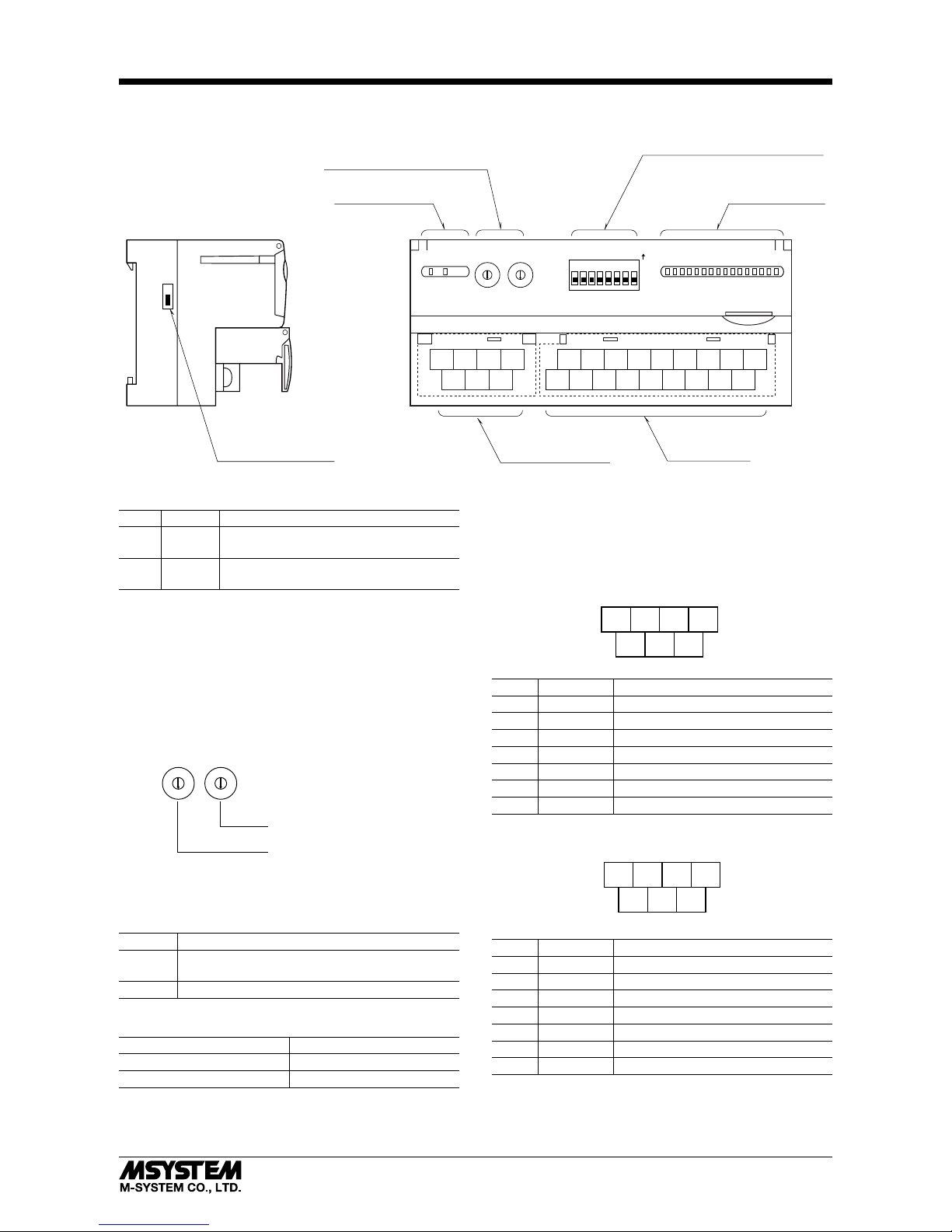
COMPONENT IDENTIFICATION
X10 X1
STATION ADD.
1 2 3 4 5 6 7 8
10 11 12 13
2341
15 16 17 18
7896145
4567
123
TERM
ON OFF
RUNPWR
ON
0 1 2 3 4 5 6 7 8 9 A B C D E F
■ FRONT VIEW■ SIDE VIEW
0
1
2
3
4
5
6
7
8
9
A
B
C
D
E
F
0
1
2
3
4
5
6
7
8
9
A
B
C
D
E
F
Terminating Resistor SW
Output Terminals
Network, Power Supply
Terminals
Status Indicator LED
Station Address Setting Rotary SW
Operating Mode Setting DIP SW (SW1)
Discrete Output
Status Indicator LED
■ STATUS INDICATOR LED
ID COLOR FUNCTION
PWR Green
Turns on when the internal 5V is supplied normally.
RUN Green
Turns on when the refresh data is received normally.
■ DISCRETE OUTPUT STATUS INDICATOR LED
LED indicators shows the signal status.
ON : LED ON (red)
OFF : LED OFF
■ STATION ADDRESS
The left switch determines the sixteenths place digit, while
the right switch does the ones place digit of the address.
(Range: 01H to 3FH)
Station Address Setting (x1)
Station Address Setting (x16)
0
1
2
3
4
5
6
7
8
9
A
B
C
D
E
F
0
1
2
3
4
5
6
7
8
9
A
B
C
D
E
F
■ OPERATING MODE
(*) Factory setting
• Output at the loss of communication (SW1-7)
SW1-7 OUTPUT AT THE LOSS OF COMMUNICATION
OFF
Hold the output (*)
(maintains the last data received normally)
ON Reset the output (turned off)
• Transfer rate (SW1-8)
SW1-8 TRANSFER RATE
OFF 12 Mbps (*)
ON 6 Mbps
Note: Be sure to set unused SW1-1 through 1-6 to OFF.
■ TERMINATING RESISTOR
To use the terminating resistor, turn the switch ON, and
OFF to invalidate. (Factory setting OFF)
■ NETWORK, POWER SUPPLY TERMINAL ASSIGNMENT
• Full-duplex communication
4
RXD+
567
123
RXD–+24V
0V
TXD+ TXD–
FG
NO. ID FUNCTION, NOTES
1 TXD+ Network (slave, transmission +)
2 TXD– Network (slave, transmission –)
3 FG FG
4 RXD+ Network (master, transmission +)
5 RXD– Network (master, transmission –)
6 +24V Power input (24V DC)
7 0V Power input (0V)
• Half-duplex communication
4
TR
+
567
123
TR
–+
24V 0V
NC NC
FG
NO. ID FUNCTION, NOTES
1 NC No connection
2 NC No connection
3 FG FG
4 TR+ Network
5 TR– Network
6 +24V Power input (24V DC)
7 0V Power input (0V)
Page 3

R7HL-DC16B
5-2-55, Minamitsumori, Nishinari-ku, Osaka 557-0063 JAPAN
Phone: +81(6)6659-8201 Fax: +81(6)6659-8510 E-mail: info@m-system.co.jp
EM-7812-H Rev.4 P. 3 / 5
■ OUTPUT TERMINAL ASSIGNMENT
10
+24V11Y112Y3
10V2Y03
Y2
13
Y5
4
Y4
14
Y7
5
Y6
15
Y9
6
Y8
16
YB
7
YA
17
YD
8YC9
YE
18
YF
NO. ID FUNCTION NO. ID FUNCTION
1 0V 0V 10 +24V
24V DC (common)
2 Y0 Output 0 11 Y1 Output 1
3 Y2 Output 2 12 Y3 Output 3
4 Y4 Output 4 13 Y5 Output 5
5 Y6 Output 6 14 Y7 Output 7
6 Y8 Output 8 15 Y9 Output 9
7 YA Output 10 16 YB Output 11
8 YC Output 12 17 YD Output 13
9 YE Output 14 18 YF Output 15
TERMINAL CONNECTIONS
Connect the unit as in the diagram below.
■ EXTERNAL DIMENSIONS unit: mm (inch)
4567
123
10 11 12 13
2341
15 16 17 18
78
9
6145
DIN RAIL
35mm wide
54 (2.13)
17 (.66)
115 (4.53)
[5 (.20)]
30 (1.18)
3 (.12)5.5 (.22)
50 (1.97)
18.5 (.73)
7–M3 SCREW
TERMINALS
for Network, POWER
18–M3 SCREW
TERMINALS
for OUTPUT
6 (.24) 6 (.24)
Page 4

R7HL-DC16B
5-2-55, Minamitsumori, Nishinari-ku, Osaka 557-0063 JAPAN
Phone: +81(6)6659-8201 Fax: +81(6)6659-8510 E-mail: info@m-system.co.jp
EM-7812-H Rev.4 P. 4 / 5
■ CONNECTION DIAGRAM
■ O
utput Connection Example
4
7
6
3
2
1
5
0V
24V DC
FG
TXD– (NC)
TXD+ (NC)
RXD– (TR–)
RXD+ (TR+)
10
17
18
1
YD
16
YB
0V
YF
15
Y9
14
Y7
13
Y5
12
Y3
11
Y1
9
YE
8
YC
7
YA
6
Y8
5
Y6
4
Y4
3
Y2
+24V
Y0
2
10
1
2
Y0
0V
+24V
–
+
18
YF
Note 1: Terminal number
s in parentheses are for half-duplex communication model.
No
te 2: In order to improve EMC performance, bond the FG terminal to ground.
Ca
ution: FG terminal is NOT a protective conductor terminal.
WIRING INSTRUCTIONS
■ SCREW TERMINAL
Torque: 0.5 N·m
■ SOLDERLESS TERMINAL
Refer to the drawing below for recommended ring tongue
terminal size. Spade tongue type is also applicable.
Recommended solderless terminal:
• Communication cables
Applicable wire size: 0.2 to 0.5 mm
2
(AWG 26 to 22)
Recommended manufacturer: Japan Solderless Terminal
MFG. Co., Ltd.
• Others
Applicable wire size: 0.25 to 1.65 mm
2
(AWG 22 to 16)
Recommended manufacturer: Japan Solderless Terminal
MFG. Co., Ltd. or Nichifu Co., Ltd.
4 (.16) min
3.2 (.13) dia.
mm (inch)
6 (.24) max
3.3 (.13) max
Page 5

R7HL-DC16B
5-2-55, Minamitsumori, Nishinari-ku, Osaka 557-0063 JAPAN
Phone: +81(6)6659-8201 Fax: +81(6)6659-8510 E-mail: info@m-system.co.jp
EM-7812-H Rev.4 P. 5 / 5
COMMUNICATION CABLE CONNECTIONS
Master Module
RXD
+
RXD
–
TXD
+
TXD
–
FG
(SHIELD)
Slave Module
RXD
+
RXD
–
TXD
+
TXD
–
FG
(SHIELD)
Slave Module
TXD
+
Terminating
Resistor
TXD
–
RXD
+
RXD
–
SHIELD
Terminating
Resistor
Master Module
TR
+
TR
–
FG
(SHIELD)
Slave Module
TR
+
TR
–
FG
(SHIELD)
Slave Module
TR
+
TR
–
SHIELD
Note: Be sure to turn ON the switch of the terminating resistor located at both ends of the modules.
Terminating
Resistor
Terminating
Resistor
■
MASTER CONNECTION
• Full-duplex communication
• Half-duplex communication
I/O DATA DESCRIPTIONS
■ DISCRETE OUTPUT
Unused
015 015
• Di
• Do
Output 0
Output 1
Output 2
Output 3
Output 15
Output 7
Output 8
:
:
:
0: OFF
1: ON
 Loading...