

M-system R7F4HML3-D-DAC32B Instruction Manual

R 7F 4 HML 3-D-DAC 32B
5-2-55, Minamitsumori, Nishinari-ku, Osaka 557-0063 JAPAN
Phone: +81(6)6659-8201 Fax: +81(6)6659-8510 E-mail: info@m-system.co.jp
EM-8002-B Rev.2 P. 1 / 12
INSTRUCTION MANUAL
NPN / PNP DISCRETE INPUT & PNP TRANSISTOR OUTPUT MODULE, 16 points each
(MECHATROLINK- III use)
MODEL
R7F4HML3-D-DAC32B
BEFORE USE ....
Thank you for choosing M-System. Before use, please check
contents of the package you received as outlined below.
If you have any problems or questions with the product,
please contact M-System’s Sales Office or representatives.
■ PACKAGE INCLUDES:
Discrete input module .........................................................(1)
DIN rail mounter slider ......................................................(2)
■ MODEL NO.
Confirm that the model number described on the product is
exactly what you ordered.
■ INSTRUCTION MANUAL
This manual describes necessary points of caution when
you use this product, including installation, connection and
basic maintenance procedures.
POINTS OF CAUTION
■ CONFORMITY WITH EU DIRECTIVES
•The actual installation environments such as panel configurations, connected devices and connected wires may
affect the protection level of this unit when it is integrated in a panel system. The user may have to review the CE
requirements in regard to the whole system and employ
additional protective measures to ensure CE conformity.
■ POWER INPUT RATING & OPERATIONAL RANGE
•Locate the power input rating marked on the product and
confirm its operational range as indicated below:
24V DC rating: 24V ±10%, approx. 100mA
■ GENERAL PRECAUTIONS
•Before you remove the unit or mount it, turn off the power
supply and I/O signal for safety.
•Before you remove the terminal block MIL connector or
mount it, turn off the power supply and I/O signal for
safety.
■ ENVIRONMENT
•Indoor use.
•When heavy dust or metal particles are present in the
air, install the unit inside proper housing with sufficient
ventilation.
•Do not install the unit where it is subjected to continuous
vibration. Do not subject the unit to physical impact.
•Environmental temperature must be within -10 to 55°C
(14 to 131°F) with relative humidity within 30 to 90% RH
in order to ensure adequate life span and operation.
•With vertical mounting, for heat dissipation leave at least
10 mm (.39 in.) at the both side of the unit.
■ WIRING
•Do not install cables close to noise sources (relay drive
cable, high frequency line, etc.).
•Do not bind these cables together with those in which
noises are present. Do not install them in the same duct.
■ AND ....
•The unit is designed to function as soon as power is supplied, however, a warm up for 10 minutes is required for
satisfying complete performance described in the data
sheet.
R 7F 4 HML 3-D -DAC 32B
5-2-55, Minamitsumori, Nishinari-ku, Osaka 557-0063 JAPAN
Phone: +81(6)6659-8201 Fax: +81(6)6659-8510 E-mail: info@m-system.co.jp
EM-8002-B Rev.2 P. 2 / 12
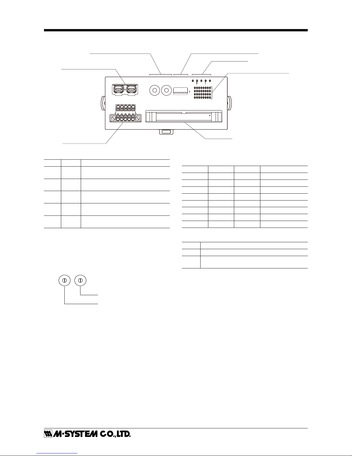
FRONT VIEW
1234
ON
SA1
×10
SA2
×1
PWR LNK2CON
LNK1ERR
LNK1 LNK2
MECHATROLINK-
III
Connector
Station Address Setting Rotary SW
Status Indicator LED
Operating Mode Setting DIP SW (SW1)
Discrete Input Status Indicator LED
I / O Connector
Power Supply Connector
■ STATUS INDICATOR LED
ID COLOR FUNCTION
PWR Green
Turns on when the internal power is supplied normally.
ERR Red
Turns on at MECHATROLINK-III communication error
CON Green
Turns on at MECHATROLINK-III connection is established
LNK1 Green
Turns on at MECHATROLINK-III LNK1
is established
LNK2 Green
Turns on at MECHATROLINK-III LNK2
is established
■ STATION ADDRESS
Station Address is selected between 03H and EFH in hexadecimal.
The SA1 switch determines the MSD, while the SA2 switch
does the LSD of the address.
(Factory setting: 03H)
Station Address Setting (LSD)
Station Address Setting (MSD)
8
9
A
B
C
D
E
F
0
1
2
3
4
5
6
7
8
9
A
B
C
D
E
F
0
1
2
3
4
5
6
7
■ OPERATING MODE
• Read Rate (SW1-1, 1-2, 1-3)
SW1-1 SW1-2 SW1-3 Read rate
OFF OFF OFF ≤10 msec. (*)
ON OFF OFF ≤1 msec.
OFF ON OFF ≤5 msec.
ON ON OFF ≤20 msec.
OFF OFF ON ≤50 msec.
ON OFF ON ≤70 msec.
OFF ON ON ≤100 msec.
ON ON ON ≤200 msec.
• Output at Loss of Communication (SW1-4)
SW1-4 Output at loss of communication
OFF
Reset the output (turned off)
ON
Hold the output (*)
(maintains the last data received normally)
(*) Factory setting
■ DISCRETE I / O STATUS INDICATOR LED
LED green indicators shows the signal status.
ON: LED ON
OFF: LED OFF
R 7F 4 HML 3-D -DAC 32B
5-2-55, Minamitsumori, Nishinari-ku, Osaka 557-0063 JAPAN
Phone: +81(6)6659-8201 Fax: +81(6)6659-8510 E-mail: info@m-system.co.jp
EM-8002-B Rev.2 P. 3 / 12
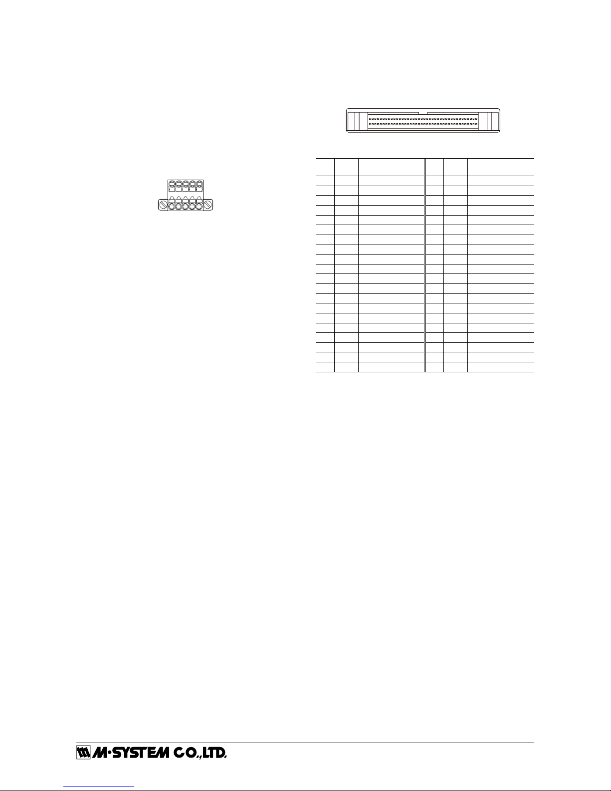
■ POWER SUPPLY
Cable connector: TFMC1,5 / 5–STF–3,5(Phoenix Contact)
(included in the package)
Applicable wire size: 0.2 − 1.5 mm
2
; stripped length 10 mm
Recommended solderless terminal
•AI0,25−10YE 0.25 mm
2
(Phoenix Contact)
•AI0,34−10TQ 0.34 mm
2
(Phoenix Contact)
•AI0,5−10WH 0.5 mm
2
(Phoenix Contact)
•AI0,75−10GY 0.75 mm
2
(Phoenix Contact)
•A1−10 1.0 mm
2
(Phoenix Contact)
•A1,5−10 1.5 mm
2
(Phoenix Contact)
12345
1. FE Functional Earth
2. NC —
3. NC —
4. +24V Power Input (24V DC)
5. 0V Power Input (0V)
■ TERMINAL ASSIGNMENTS
• I / O Connection
Recommended cable connector: XG4M-4030 (OMRON)
The cable connector is not included in the package.
39
40
1
2
PIN
No.
ID FUNCTION
PIN
No.
ID FUNCTION
1 V+
External excitation
2 V+
External excitation
3 V– Out. Common 4 V– Out. Common
5 Y15 OUTPUT 15 6 Y7 OUTPUT 7
7 Y14 OUTPUT 14 8 Y6 OUTPUT 6
9 Y13 OUTPUT 13 10 Y5 OUTPUT 5
11 Y12 OUTPUT 12 12 Y4 OUTPUT 4
13 Y11 OUTPUT 11 14 Y3 OUTPUT 3
15 Y10 OUTPUT 10 16 Y2 OUTPUT 2
17 Y9 OUTPUT 9 18 Y1 OUTPUT 1
19 Y8 OUTPUT 8 20 Y0 OUTPUT 0
21 NC NC 22 NC NC
23 COM In. Common 24 COM In. Common
25 X15 INPUT 15 26 X7 INPUT 7
27 X14 INPUT 14 28 X6 INPUT 6
29 X13 INPUT 13 30 X5 INPUT 5
31 X12 INPUT 12 32 X4 INPUT 4
33 X11 INPUT 11 34 X3 INPUT 3
35 X10 INPUT 10 36 X2 INPUT 2
37 X9 INPUT 9 38 X1 INPUT 1
39 X8 INPUT 8 40 X0 INPUT 0
R 7F 4 HML 3-D -DAC 32B
5-2-55, Minamitsumori, Nishinari-ku, Osaka 557-0063 JAPAN
Phone: +81(6)6659-8201 Fax: +81(6)6659-8510 E-mail: info@m-system.co.jp
EM-8002-B Rev.2 P. 4 / 12
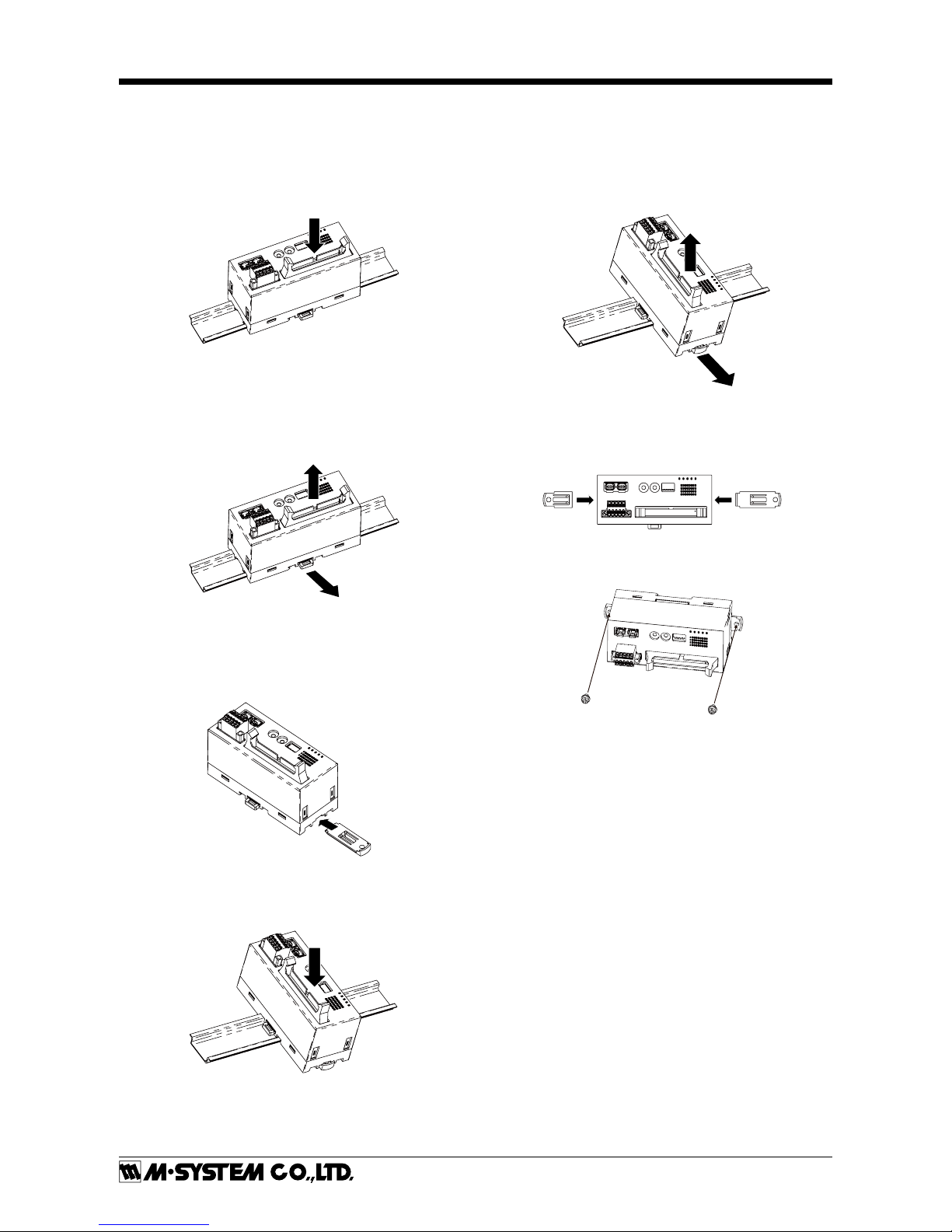
MOUNTING INSTRUCTIONS
■ DIN RAIL MOUNTING (PARALLEL)
• Mounting
1) Set the upper hook at the rear side of the unit on the
DIN rail.
2) Push in the lower.
1
2
• Dismounting
1) Push down the DIN rail mounter slider with tip of a minus screwdriver.
2) Pull the lower of the unit.
3) Remove the upper hook of the unit from the DIN rail.
1
3
2
■ DIN RAIL MOUNTING (RIGHT ANGLE)
• Mounting
1) Insert the longer DIN rail mounter slider until it clicks
twice, as shown below.
1
2) Set the upper hook at the rear side of the unit on the
DIN rail.
3) Push in the lower.
2
3
Note: leave at least 10 mm (.39 in.) at the both side of the unit.
• Dismounting
1) Push down the DIN rail mounter slider with tip of a minus screwdriver.
2) Pull the lower of the unit.
3) Remove the upper hook of the unit from the DIN rail.
1
2
3
■ SURFACE MOUNTING
1) Insert the two DIN rail mounter sliders until it clicks
once, as shown below.
11
2) Mount the unit with M4 screws referring the External
Dimensions. (Torque: 1.4N∙m)
 Loading...