

Page 1

R3-WT1
5-2-55, Minamitsumori, Nishinari-ku, Osaka 557-0063 JAPAN
Phone: +81(6)6659-8201 Fax: +81(6)6659-8510 E-mail: info@m-system.co.jp
EM-8388 Rev.3 P. 1 / 5
MULTI POWER INPUT MODULE
MODEL
R3-WT1
INSTRUCTION MANUAL
BEFORE USE ....
Thank you for choosing M-System. Before use, please check
the contents of the package you received as outlined below.
If you have any problems or questions with the product,
please contact M-System’s Sales Office or representatives.
■ PACKAGE INCLUDES:
Multi power input module .............................................(1)
■ MODEL NO.
Confirm that the model number described on the product is
exactly what you ordered.
■ INSTRUCTION MANUAL
This manual describes necessary points of caution when
you use this product, including installation, connection and
basic maintenance procedures.
In order to set up the software setting of this module, PC
Configurator Software (model: R3CON) is required. For
more information, please refer to the users manual for the
R3CON.
The R3CON PC Configurator Software is downloadable at
MSystem’s web site: http://www.m-system.co.jp.
POINTS OF CAUTION
■ HOT INSERTION/REMOVAL OF MODULES
•Removing or replacing modules does not affect other modules on the same backplane. It is possible to replace them
without removing the power supply. However, replacing
multiple modules at once may greatly change line voltage
levels. We recommend that you replace them one by one.
■ ENVIRONMENT
•Indoor use
•When heavy dust or metal particles are present in the
air, install the unit inside proper housing with sufficient
ventilation.
•Do not install the unit where it is subjected to continuous
vibration. Do not subject the unit to physical impact.
•Environmental temperature must be within -10 to +55°C
(14 to 131°F) with relative humidity within 30 to 90% RH
in order to ensure adequate life span and operation.
■ WIRING
•Do not install cables close to noise sources (relay drive
cable, high frequency line, etc.).
•Do not bind these cables together with those in which
noises are present. Do not install them in the same duct.
■ AND ....
•The unit is designed to function as soon as power is supplied, however, a warm up for 10 minutes is required for
satisfying complete performance described in the data
sheet.
INSTALLATION
Use the Installation Base (model: R3-BSx).
Page 2
R3-WT1
5-2-55, Minamitsumori, Nishinari-ku, Osaka 557-0063 JAPAN
Phone: +81(6)6659-8201 Fax: +81(6)6659-8510 E-mail: info@m-system.co.jp
EM-8388 Rev.3 P. 2 / 5
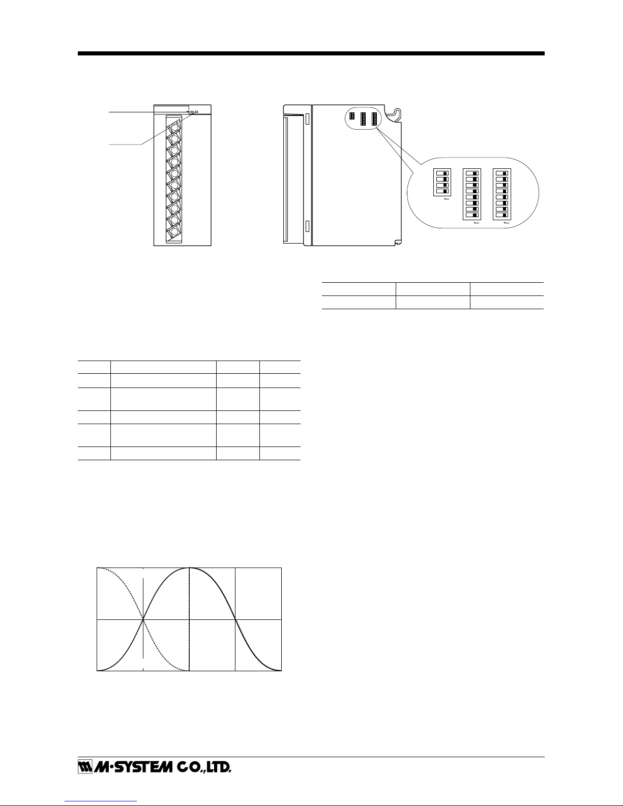
COMPONENT IDENTIFICATION
■ FRONT VIEW
RUN LED
ERR LED
1
2
3
4
5
6
7
8
9
10
■ SIDE VIEW
ON
8
7
6
5
4
3
2
1
SW1SW2
ON
8
7
6
5
4
3
2
1
SW3
ON
4
3
2
1
■ SIDE DIP SW
(*) Factory setting
Be sure to turn off the power supply to the module whenchanging settings. Reset the count after setting changes.
• SW1, SW2
Count Reset Enable : Back to 0 at overflow
Disable : Halt at 999 999 999
Power Factor may start hunting around 1.
SW FUNCTION
0 : OFF(*)
1 : ON
SW1-2 active energy count reset disable enable
SW1-3 active energy
bidirectional current
disable enable*
1
SW1-6 active energy count reset disable enable
SW1-7 active energy
bidirectional current
disable enable*
1
SW2-1 power factor LEAD polarity normal inverted
*1. Both active energy count reset and reactive energycount re-
set are fixed at ‘disable.’
The count stops at ±999 999 999.
When the bidirectional current computation is enabled,the
outgoing active energy and the LEAD reactive energy become 0.
Power Factor Polarity
0
-1.0
1.0
COS
q
DEG
90-90-180
(LEAD)
180
(LAG)
Inverted
Normal
• SW3
The maximum available active energy count is 109.
SW
0 : OFF(*)
1 : ON
SW3-1 ---- count reset
How to Reset
Set the SW3-1 to ON and turn on the power supply. Wait
until the RUN LED (red) starts flashing and the ERR LED
(green) turns on. Then turn the power supply off and reset
the SW3-1 to OFF.
Turn all switches off other than the above.
■ STATUS INDICATOR LED
RUN indicator: Bi-color (red/green) LED;
Red when the bus A operates normally;
Green when the bus B operates normally;
Amber when both buses operate normally.
ERR indicator: Bi-color (red/green) LED;
Red with the input abnormality;
Green in normal operating conditions.
Page 3

R3-WT1
5-2-55, Minamitsumori, Nishinari-ku, Osaka 557-0063 JAPAN
Phone: +81(6)6659-8201 Fax: +81(6)6659-8510 E-mail: info@m-system.co.jp
EM-8388 Rev.3 P. 3 / 5
PC CONFIGURATOR
The following parameters can be set with using PC Configurator Software (model: R3CON):
•Enter fine 0% adjustment value
•Enter fine 100% adjustment value
•Low-end cutout value in %
•Primary voltage
•Primary voltage, Exponent (10
n
)
•Primary current
•Primary current, exponent 10
n
•Active/Reactive Power, span value
•Active/Reactive Power, exponent 10
n
•Active Energy unit, exponent 10
n
•Minimum totalized value
•Maximum totalized value
•Reactive Energy unit, exponent 10
n
•Minimum totalized value
•Maximum totalized value
TRANSMISSION DATA DESCRIPTIONS
ADDRESS CONTENTS
n Active power *
2
n + 1 Reactive power *
2
n + 2 Power factor *
2
n + 3 Frequency *
2
n + 4 Incoming active energy (lower bits) *
3
n + 5 Incoming active energy (upper bits)
n + 6 Outgoing active energy (lower bits) *
3
n + 7 Outgoing active energy (upper bits)
n + 8 LAG reactive energy (lower bits) *
3
n + 9 LAG reactive energy (upper bits)
n +10 LEAD reactive energy (lower bits) *
3
n +11 LEAD reactive energy (upper bits)
n +12 0
n +13 0
n +14 0
n +15 0
R3CON type ID WT1****
Network module 4, 8, 16
data allocation
mode example *
1
n = I/O address on the installation base
Factory setting = 1 kWh and 1 kvarh per bit.
Data address depends upon the data allocation mode as
indicated below:
4 (n thr. n+3)
8 (n thr. n+7)
16 (n thr. n+15)
*1. Fixed at 16 for the R3-NPx.
*2. 16-bit data
*3. 32-bit data
I/O DATA DESCRIPTIONS
■ 16-BIT DATA
■
0
15
16-bit binary data. Minus values are represented in 2’s complements.
32-BIT DATA
1631
0
15
stigid rewolstigid reppu
32-bit binary data. Minus values are represented in 2’s complements.
Page 4

R3-WT1
5-2-55, Minamitsumori, Nishinari-ku, Osaka 557-0063 JAPAN
Phone: +81(6)6659-8201 Fax: +81(6)6659-8510 E-mail: info@m-system.co.jp
EM-8388 Rev.3 P. 4 / 5
TERMINAL CONNECTIONS
Connect the unit as in the diagram below.
■ DIMENSIONS mm (inch)
130 (5.12)
52.5 (2.07)
109 (4.29)
7.9
(.31)
1
2
3
4
5
6
7
8
9
10
10–M3.5
SCREW
POSITIONING
GUIDE
TERMINAL
COVER
■ CONNECTION DIAGRAM
BUS CONNECTOR
INTERNAL
POWER
INTERNAL
BUS A
INTERNAL
BUS B*
VOLTAGE
INPUT
1
3
4
2
LOAD
123
SOURCE
P2V
P1Uvu
FUSE
VT
Vv
P3
Uu
CURRENT
INPUT
5
7
8
6
LOAD
123
SOURCE
k
l
CT
L
K
1L
1S
3L
3S
k
l
L
K
■ 3-PHASE/3-WIRE
BUS CONNECTOR
INTERNAL
POWER
INTERNAL
BUS A
INTERNAL
BUS B*
■ SINGLE-PHASE/3-WIRE
BUS CONNECTOR
INTERNAL
POWER
INTERNAL
BUS A
INTERNAL
BUS B*
■ SINGLE-PHASE/2-WIRE
VOLTAGE
INPUT
1
3
4
2
LOAD
12
SOURCE
P2
P1
5
7
8
6
VUv
u
VT
FUSE
CURRENT
INPUT
LOAD
12
SOURCE
1L
1S
k
l
L
K
CT
*For dual redundant communication.
VOLTAGE
INPUT
1
3
4
2
LOAD
1N2
SOURCE
P0V
P1Uvu
FUSE
VT
Vv
P2
Uu
CURRENT
INPUT
5
7
8
6
LOAD
1N2
SOURCE
k
l
CT
L
K
1L
1S
2L
2S
k
l
L
K
Page 5

R3-WT1
5-2-55, Minamitsumori, Nishinari-ku, Osaka 557-0063 JAPAN
Phone: +81(6)6659-8201 Fax: +81(6)6659-8510 E-mail: info@m-system.co.jp
EM-8388 Rev.3 P. 5 / 5
WIRING INSTRUCTIONS
■ SCREW TERMINAL
Torque: 0.8 N·m
■ SOLDERLESS TERMINAL mm (inch)
Refer to the drawing below for recommended ring tongue
terminal size. Spade tongue type is also applicable. Solderless terminals with insulation sleeve do not fit.
Applicable wire size: 0.75 – 2 mm
2
3.7 (.15) dia.
6 min.
(.24)
14.5 (.57) max.
7 max.
(.28)
3.5 (.14) max.
 Loading...