

Page 1

INSTRUCTION MANUAL
TEMPERATURE CONTROL MODULE
MODEL
R3-TC2
CONTENTS
BEFORE USE .... ........................................................................................................... 2
POINTS OF CAUTION ...................................................................................................... 2
COMPONENT IDENTIFICATION ..........................................................................................2
INSTALLATION ............................................................................................................. 2
TERMINAL CONNECTIONS ............................................................................................... 3
WIRING INSTRUCTIONS .................................................................................................. 4
FUNCTION DESCRIPTIONS ............................................................................................... 5
SYSTEM CONFIGURATIONS & CONTROL EXAMPLES ................................................................ 6
OPERATION ................................................................................................................. 7
MODBUS COMMUNICATION ........................................................................................... 12
SETTING .................................................................................................................. 14
UNIVERSAL INPUT ...................................................................................................... 16
CONTROL OUTPUT ...................................................................................................... 19
LOOP ...................................................................................................................... 21
BANK ...................................................................................................................... 28
EVENT INPUT ............................................................................................................. 34
CT INPUT ................................................................................................................. 35
AUTO-TUNING............................................................................................................ 37
5-2-55, Minamitsumori, Nishinari-ku, Osaka 557-0063 JAPAN
Phone: +81(6)6659-8201 Fax: +81(6)6659-8510 E-mail: info@m-system.co.jp
EM-8468 Rev.3 P. 1 / 37
Page 2

R3-TC2
BEFORE USE ....
Thank you for choosing M-System. Before use, please check
contents of the package you received as outlined below.
If you have any problems or questions with the product,
please contact M-System’s Sales Office or representatives.
■ PACKAGE INCLUDES:
Temperature control module
(control module + CJC sensor, 2 pcs.) .................................(1)
■ MODEL NO.
Confirm Model No. marking on the product to be exactly
what you ordered.
■ INSTRUCTION MANUAL
This manual describes necessary points of caution when
you use this product, including installation, connection and
basic maintenance procedures.
POINTS OF CAUTION
■ HOT INSERTION/REMOVAL OF MODULES
• Removing or replacing modules does not affect other modules on the same backplane. It is possible to replace them
without removing the power supply. However, replacing
multiple modules at once may greatly change line voltage
levels. We recommend that you replace them one by one.
■ ENVIRONMENT
• Indoor use.
• When heavy dust or metal particles are present in the
air, install the unit inside proper housing with sufficient
ventilation.
• Do not install the unit where it is subjected to continuous
vibration. Do not subject the unit to physical impact.
• Environmental temperature must be within -10 to +55°C
(14 to 131°F) with relative humidity within 30 to 90% RH
in order to ensure adequate life span and operation.
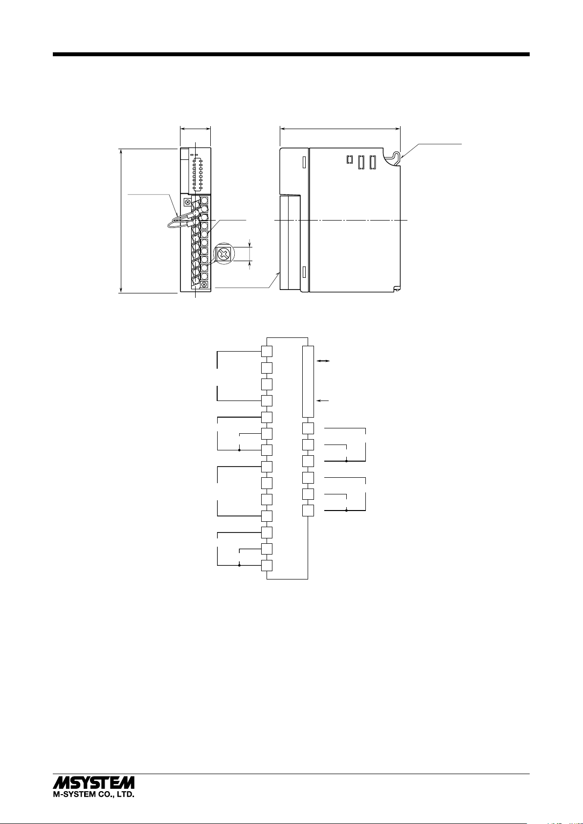
COMPONENT IDENTIFICATION
■ FRONT VIEW
RUN LED
ERR LED
CJC SENSOR(2)
RUN1
AUTO1
ERR1
ALM1
RUN2
AUTO2
ERR2
ALM2
1
11
2
12
3
13
13
4
14
5
15
6
16
7
17
8
18
9
19
10
20
Loop Status Indicator
■ STATUS INDICATOR LED
RUN indicator: Bi-color (red/green) LED;
Red when the internal bus operates normally.
ERR indicator: Bi-color (red/green) LED;
Red at device error;
Green in normal operating conditions.
Loop status indicators: Red LED
RUN1: Turns on while loop 1 is in operation.
AUTO1: Turns on during auto mode, turns off during
manual mode with loop 1
ERR1: Turns on at error with loop 1
ALM1: Turns on at alarm with loop 1
RUN2: Turns on while loop 2 is in operation.
AUTO2: Turns on during auto mode, turns off during
manual mode with loop 2
ERR2: Turns on at error with loop 2
ALM2: Turns on at alarm with loop 2
INSTALLATION
Use the Installation Base (model: R3-BSx).
■ WIRING
• Do not install cables close to noise sources (relay drive
cable, high frequency line, etc.).
• Do not bind these cables together with those in which
noises are present. Do not install them in the same duct.
■ UNUSED INPUT CHANNELS
• Unused channels can be specified and set so on the PC
Configurator Software (model: R3CON) without needing
to short at the field terminals.
■ AND ....
• The unit is designed to function as soon as power is supplied, however, a warm up for 10 minutes is required for
satisfying complete performance described in the data
sheet.
5-2-55, Minamitsumori, Nishinari-ku, Osaka 557-0063 JAPAN
Phone: +81(6)6659-8201 Fax: +81(6)6659-8510 E-mail: info@m-system.co.jp
EM-8468 Rev.3 P. 2 / 37
Page 3
TERMINAL CONNECTIONS
Connect the unit as in the diagram below.
■ EXTERNAL DIMENSIONS unit: mm (inch)
R3-TC2
CJC SENSOR (2)
130 (5.12)
■ CONNECTION DIAGRAM
27.5 (1.08)
1
11
20–M3
2
12
SCREW
3
13
13
4
14
5
15
6
16
7
17
8
18
9
19
10
20
TERMINAL COVER
Pv1
UNIVERSAL INPUT
CT 1
Pv2
UNIVERSAL INPUT
Di 1
CT 2
Di 2
109 (4.29)
POSITIONING
GUIDE
6.2
(.24)
1
2
INTERNAL BUS
3
4
5
6
7
11
12
13
14
INTERNAL POWER
BUS CONNECTOR
+
8
+
9
10
18
19
20
Mv2
–
+
+
Do2
–
Mv1
Do1
15
16
17
5-2-55, Minamitsumori, Nishinari-ku, Osaka 557-0063 JAPAN
Phone: +81(6)6659-8201 Fax: +81(6)6659-8510 E-mail: info@m-system.co.jp
EM-8468 Rev.3 P. 3 / 37
Page 4
R3-TC2
INTERNAL BUS
8
9
18
19
20
10
1
2
3
4
5
6
7
11
12
13
14
15
16
17
+
+
–
Mv2
+
+
–
Pv1
UNIVERSAL INPUT
CT 1
Di 1
Di 2
INTERNAL POWER
CT 2
Pv2
UNIVERSAL INPUT
Mv1
Do2
Do1
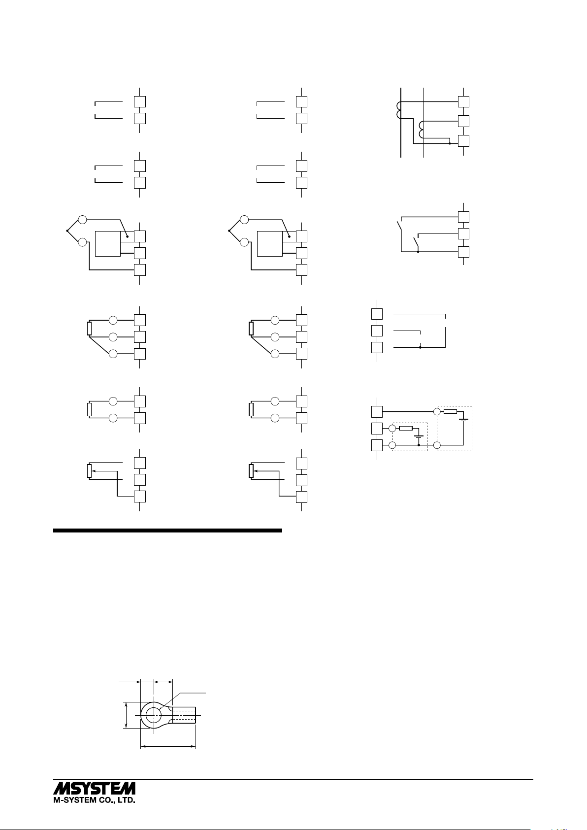
UNIVERSAL INPUT CONNECTION (Pv2) e.g.
BUS CONNECTOR
■ UNIVERSAL INPUT CONNECTION (Pv1) e.g.
•DC Voltage (-10 – +10V DC)
•DC Current (0 – 20mA DC)
+
INPUT
•DC Voltage (-1000 – +1000mV DC)
INPUT
•Thermocouple
–+–
CJC
+
SENSOR
comp. leadwire
•RTD/Resistor (3-wire)
1
–
2
–
2
+
4
–
2
3
+
4
A
2
B
3
B
4
■
•DC Voltage (-10 – +10V DC)
•DC Current (0 – 20mA DC)
+
INPUT
11
–
12
•DC Voltage (-1000 – +1000mV DC)
INPUT
•Thermocouple
–+–
+
comp. leadwire
•RTD/Resistor (3-wire)
–
12
+
CJC
SENSOR
14
–
12
13
+
14
A
12
B
13
B
14
■ CT 1 / CT 2 CONNECTION e.g.
•Clamp-on current Sensor
Power Side
k
l
k
l
5
6
7
Load Side
■ DISCRETE INPUT CONNECTION e.g.
Di 1
Di2
15
16
17
■ CONTROL OUTPUT 1 & 2 CONNECTION e.g.
+
10
8
+
9
–
Mv1
Mv2
•RTD/Resistor (2-wire)
A
B
•Potentiometer
max.
min.
+
–
2
3
2
3
•RTD/Resistor (2-wire)
A
B
•Potentiometer
max.
min.
4
WIRING INSTRUCTIONS
■ SCREW TERMINAL
Torque: 0.5 N·m
■ SOLDERLESS TERMINAL
Refer to the drawing below for recommended ring tongue
terminal size. Spade tongue type is also applicable. Solderless terminals with insulation sleeve do not fit.
Applicable wire size: 0.3 – 0.75 mm
Recommended manufacturer: Japan Solderless Terminal
MFG. Co., Ltd., Nichifu Co., Ltd.
2
■ CONTROL OUTPUT 3 & 4 CONNECTION e.g.
12
13
18
19
20
+
12
–
13
Do2
+
–
Do1
+
–
14
3max
6max
4min
12max
3.2 dia.
(mm)
5-2-55, Minamitsumori, Nishinari-ku, Osaka 557-0063 JAPAN
Phone: +81(6)6659-8201 Fax: +81(6)6659-8510 E-mail: info@m-system.co.jp
EM-8468 Rev.3 P. 4 / 37
Page 5

FUNCTION DESCRIPTIONS
R3-TC2
■ UNIVERSAL INPUT
• Input types
1) DC: 0 − 20mA / -1000 − +1000mV / -10 − +10V
2) Potentiometer: Max. total resistance 4000Ω
3) Resistor: Max. 4000Ω
4) RTD: Pt 100 / Pt 500 / Pt 1000 / Pt 50Ω / JPt 100 /
Ni 508.4Ω / Cu 10
5) Thermocouple: (PR) / K / E / J / T / B / R / S / C / N / U /
L / P
• Two input points can be assigned respectively with one of
the selections (1) through (5).
• Sampling cycle: 100 milliseconds
• Burnout detection available for potentiometer, resistor,
RTD and thermocouple inputs
• Cold junction compensation sensors for thermocouple input included in the product package
• Fine input adjustment available
• DC, potentiometer and resistor inputs can be scaled into
temperature ranges.
• First order lag filter for input signals
■ CONTROL OUTPUT
• Output types
1) 12V pulse / 0 − 20mA DC / 0 − 10V DC
selected by model number suffix code when ordering
2) Open collector
• Two output points by the selection (1) plus two output
points with the selection (2)
• Control cycle 0.1 to 99.9 seconds
(100 msec. fixed for control output 0 − 20 mA and 0 − 10
V DC)
• Output resolution 1 millisecond
• PV, SP and MV signals can be scaled and provided as duty
ratio output; Alarm contact output (ON/OFF) also available
• Minimum ON/OFF pulse width can be specified for relay
life protection
■ EVENT INPUT
• Two discrete input points can be assigned to a specific
event.
• Event types
• Switching banks / Switching operation / Switching manual/auto mode / Switching local/remote SP
■ CT INPUT
• Input type
M-System clamp-on current sensor (model: CLSE)
• Two input points can be assigned respectively to monitor
specific control output status.
• One signal can watch heater wire break, SSR shortcircuit
failure and overload at once.
• Control output must be turned on for at the minimum
of 110 milliseconds to detect a heater wire break; must
be turned off for at the minimum of 200 milliseconds to
detect an SSR shortcircuit failure.
■ COMMUNICATION
• Monitoring and setting can be performed easily with PC
Configurator Software (model: R3CON).
• Various values can be read out via network communication (data allocation mode: 8)
• Modbus interface module (model: R3-NM3) available with
the R3 extension area communication realizes a large capacity data reading/writing.
■ CONTROL LOOP
• Control strategies
1) Standard PID control
2) Heating-cooling PID control
(independent PID operation for heating and cooling)
3) Heating-cooling ON/OFF control
(heating-only or cooling-only output is possible.)
• Two control loops can be assigned respectively to one of
the selections (1) through (3).
• Limit cycle method auto-tuning
• Direct/reverse action selectable for standard PID control
• Input 2 can be cascaded to loop 1 as its SP (remote SP)
• MV tracking function: MV in manual mode is carried on
into auto mode.
• High/low limits selectable for SP and MV values
• Specific MV values applicable at STOP/abnormality.
• Three PV alarm modes selectable for each loop
• Four bank settings available for each loop; Banks can be
switched during operation.
• Bank setting
• SP / SP rise ramp / SP fall ramp / P / I / D / Cooling P /
Cooling I / Cooling D / Heating sensitivity / Cooling sensitivity / Deadband / PV alarm high/low limits
5-2-55, Minamitsumori, Nishinari-ku, Osaka 557-0063 JAPAN
Phone: +81(6)6659-8201 Fax: +81(6)6659-8510 E-mail: info@m-system.co.jp
EM-8468 Rev.3 P. 5 / 37
Page 6
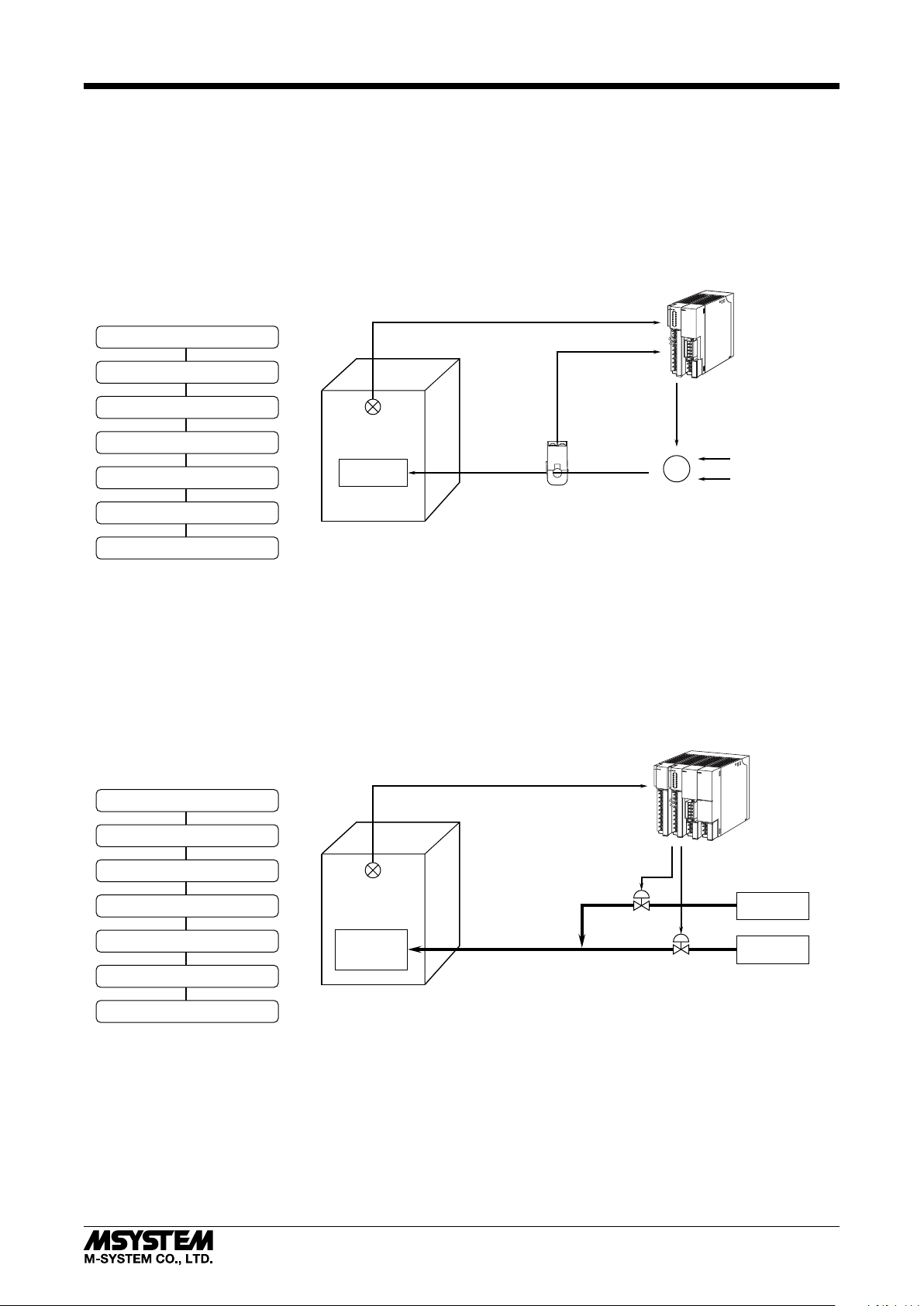
SYSTEM CONFIGURATIONS & CONTROL EXAMPLES
CONTROL OUTPUT 3 (Do1)
■ 1 loop heating ON/OFF control and heater wire break detection
1. Installation example:
• Base (model: R3–BS)
• Interface Module (model: R3–NM3)
• Temperature Control Module (model: R3–TC2)
• Clamp-on Current Sensor (model: CLSE)
• Oven
• Heater
• Relay
• Temperature sensor
R3-TC2
2. Proccess until start operating:
Turn ON power supply
Set input sensor type and range
Set CT input to wire break detection
Temp. Sensor
Select control mode (ON/OFF Control)
Specify target temperature (SP)
Select operation mode (auto)
Start operation
■ 1 loop heating and cooling control (PID)
1. Installation example:
• Base (model: R3–BS)
• Power Supply Module (R3–PS1)
• Interface Module (model: R3–NM3)
• Temperature Control Module (model: R3–TC2)
• DC Voltage Input Module (model: R3–SV4)
(Other R3 modules also available)
• Object to heat/cool
• Temperature sensor
2. Proccess until start operating:
Turn ON power supply
Set input sensor type and range
Heater
Oven
UNIVERSAL INPUT 2 (Pv2)
CT INPUT 1
CLSE
UNIVERSAL INPUT 1 (Pv1)
R3–BS
R3–NM3
R3–TC2
Ry
Relay
Relay Power
Heater Power
R3–BS
R3–PS1
R3–NM3
R3–TC2
R3–SV4
Select control mode
Set deadband
Specify target temperature (SP)
(PID)
Temp. Sensor
Object to
heat/cool
Select operation mode (auto)
Start operation
Note: The examples above are for single loop, however, dual loop control is also availabe using only one R3-TC2.
5-2-55, Minamitsumori, Nishinari-ku, Osaka 557-0063 JAPAN
Phone: +81(6)6659-8201 Fax: +81(6)6659-8510 E-mail: info@m-system.co.jp
Control output 2 (Mv2) Control output 1 (Mv1)
Cold water
Hot water
EM-8468 Rev.3 P. 6 / 37
Page 7
R3-TC2
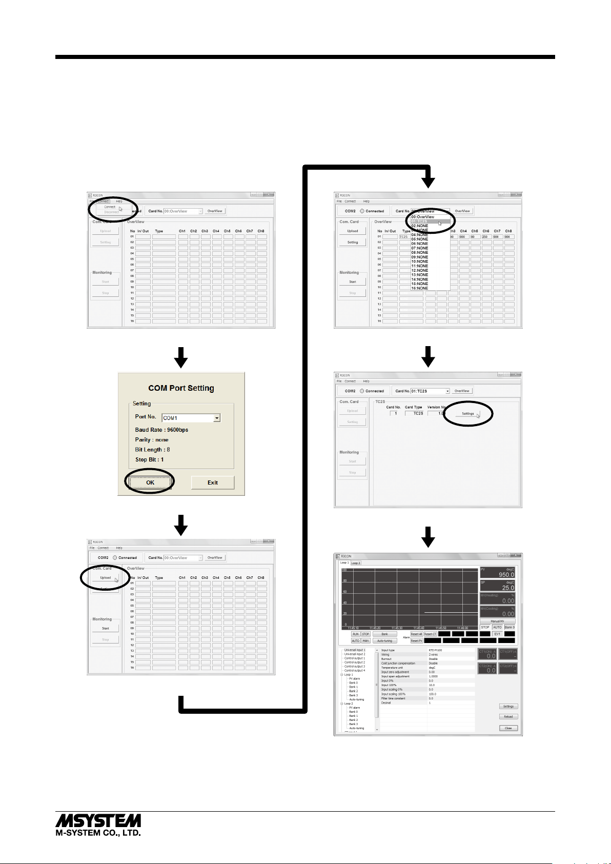
OPERATION
■ GETTING READY WITH PC CONFIGURATOR SOFTWARE (model: R3CON)
The PC Configurator Software is used to set up various parameters for the Temperature Controller Module and to perform
auto-tuning.
Connect the CONFIG port to the PC and start up the R3CON. The flowchart below shows how to move to the Controller’s
setting window. In this example, the R3-TC2 is supposed to be installed in the slot 1.
Click [Connect] under [Connect] menu
Choose a COM port and click OK
Choose ‘TC2S’ from the list
Click [Settings] button
Click [Upload] button
5-2-55, Minamitsumori, Nishinari-ku, Osaka 557-0063 JAPAN
Phone: +81(6)6659-8201 Fax: +81(6)6659-8510 E-mail: info@m-system.co.jp
EM-8468 Rev.3 P. 7 / 37
Page 8

■ R3CON CONFIGURATION WINDOW
For setting details, refer to the R3-TC2 instruction manual.
Alternatively press F5 button on the keyboard to reload.
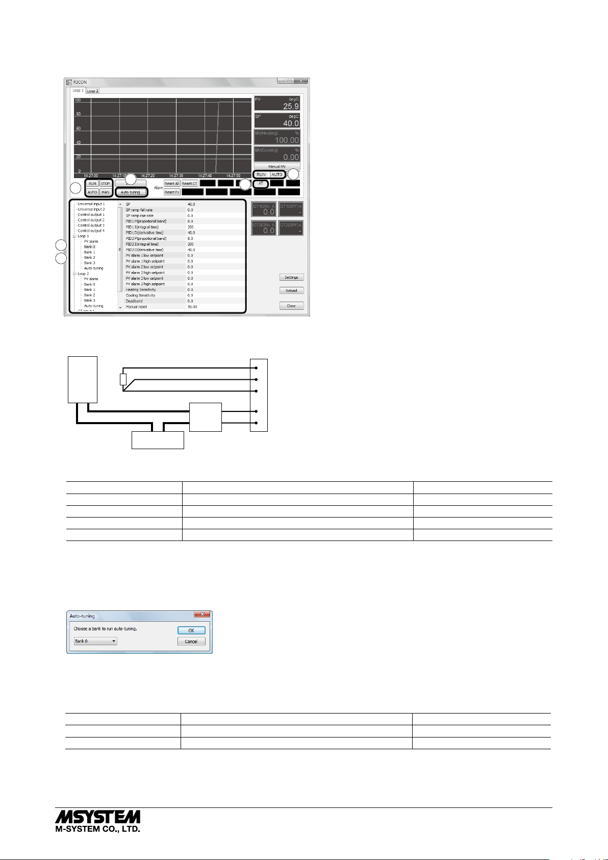
The Controller’s setting window is as shown below.
The trend graph shows real time PV and MV status, and parameters and operation status can be monitored.
(1) MONITOR WINDOW
Trend graph shows PV, SP and MV for loop 1 and 2.
Choose Loop 1 or Loop 2 tub at the top.
Trend data for both loops is continuously stored
1
even though only one loop is chosen at a moment.
(2) SWITCHING OPERATION / MODE
Control operation and mode is set with the buttons.
8
7
6
2
(3) ALARM INDICATORS / RESET BUTTONS
3
Alarm status of the selected loop is indicated.
Various alarm status can be reset by clicking [Reset PV],
[Reset CT] and [Reset All].
5
(4) SETTING ITEMS TREE & LIST
Setting parameters are grouped in the menu tree.
4
Choose a specic group to show a parameter list
to choose from. Modied selections / values are written
9
in the device immediately.
13
(5) CT INPUT INDICATORS
CTx(ON) display shows current value when the relevant
control output is ON; while CTx(OFF) shows current
when it is OFF.
‘ - ’ shows that the control output has not been switched
on or off during the last control cycle.
R3-TC2
10
11
12
(6) BANK
[Switch Bank] dialog box appears when [Bank] button
is clicked.
Choose a bank and click OK to apply the change.
(7) AUTO-TUNING
[Auto-tuning] dialog box appears when [Auto-tuning]
is clicked.
Choose a bank and click OK to start auto-tuning for the
specied bank.
(8) MANUAL MV
[Set MV Manually] dialog box appears when
[Manual MV] button is clicked.
Enter a MV value and click OK to apply the change
(only in MAN mode).
(9) SETTINGS
Graph scales in the trend graph and display language
can be changed.
[Settings] dialog box appears when the button is clicked.
(10) Y axis max / Y axis min
Specify a full-scale temperature range for Y axis.
Selectable from -9999.9999 to +9999.9999.
Minimum span is of 0.2.
(11) X axis time span
Specify a full-scale time span for X axis.
Selectable among:
10 sec. 30 sec. 1 min. 3 min. 5 min.
10 min. 15 min. 30 min. 1 hour 2 hours
(12) Display Language
English and Japanese can be switched.
(13) RELOAD
Used to upload the setting from the device.
5-2-55, Minamitsumori, Nishinari-ku, Osaka 557-0063 JAPAN
Phone: +81(6)6659-8201 Fax: +81(6)6659-8510 E-mail: info@m-system.co.jp
EM-8468 Rev.3 P. 8 / 37
Page 9
■ SETTING EXAMPLE 1: TEMPERATURE CONTROL WITH STANDARD PID
The following is an example to control temperature of loop 1 to 40.0°C by standard PID control.
R3-TC2
4
5
2
8
6
4
(1) Connect Pt100 to the universal input terminal 1 to measure temperature. Connect also an SSR and a heater to the control
output 1.
Pt100
Heater
SSR
Power Supply
Universal Input 1
Control Output 1
R3-TC2PS
(2) Go to the setting items tree and change the following parameters.
SETTING ITEMS TREE PARAMETER SELECTION
Universal input 1 Input type RTD Pt 100
Universal input 1 Wiring 3 wires
Control output 1 Output assignment Loop 1, Heating control
Loop 1, Bank 0 SP (setpoint value) 40.0
(3) Confirm that Pt100 is correctly connected to the universal input 1 and the controlled object (heater, etc) for heating control
to the control output 1.
(4) Click RUN button and AUTO button located below the trend graph to start control operations. Indicators STOP and MAN
are switched respectively to RUN and AUTO.
(5) Click Auto-tuning button located below the trend graph to show the Auto-tuning dialog box. Choose Bank 0 and click OK.
(6) The Controller starts auto-tuning. Indicator AT starts blinking. Click STOP button to stop the auto-tuning.
(7) Indicator AT stops blinking to start control operation when the auto-tuning is complete.
(8) Go to the setting items tree and change the following parameters so that the control operation automatically starts at the
start up of the device.
SETTING ITEMS TREE PARAMETER SELECTION
Loop 1 Operation at startup RUN
Loop 1 Control mode at startup AUTO
Now the setting is complete.
5-2-55, Minamitsumori, Nishinari-ku, Osaka 557-0063 JAPAN
Phone: +81(6)6659-8201 Fax: +81(6)6659-8510 E-mail: info@m-system.co.jp
EM-8468 Rev.3 P. 9 / 37
Page 10
R3-TC2
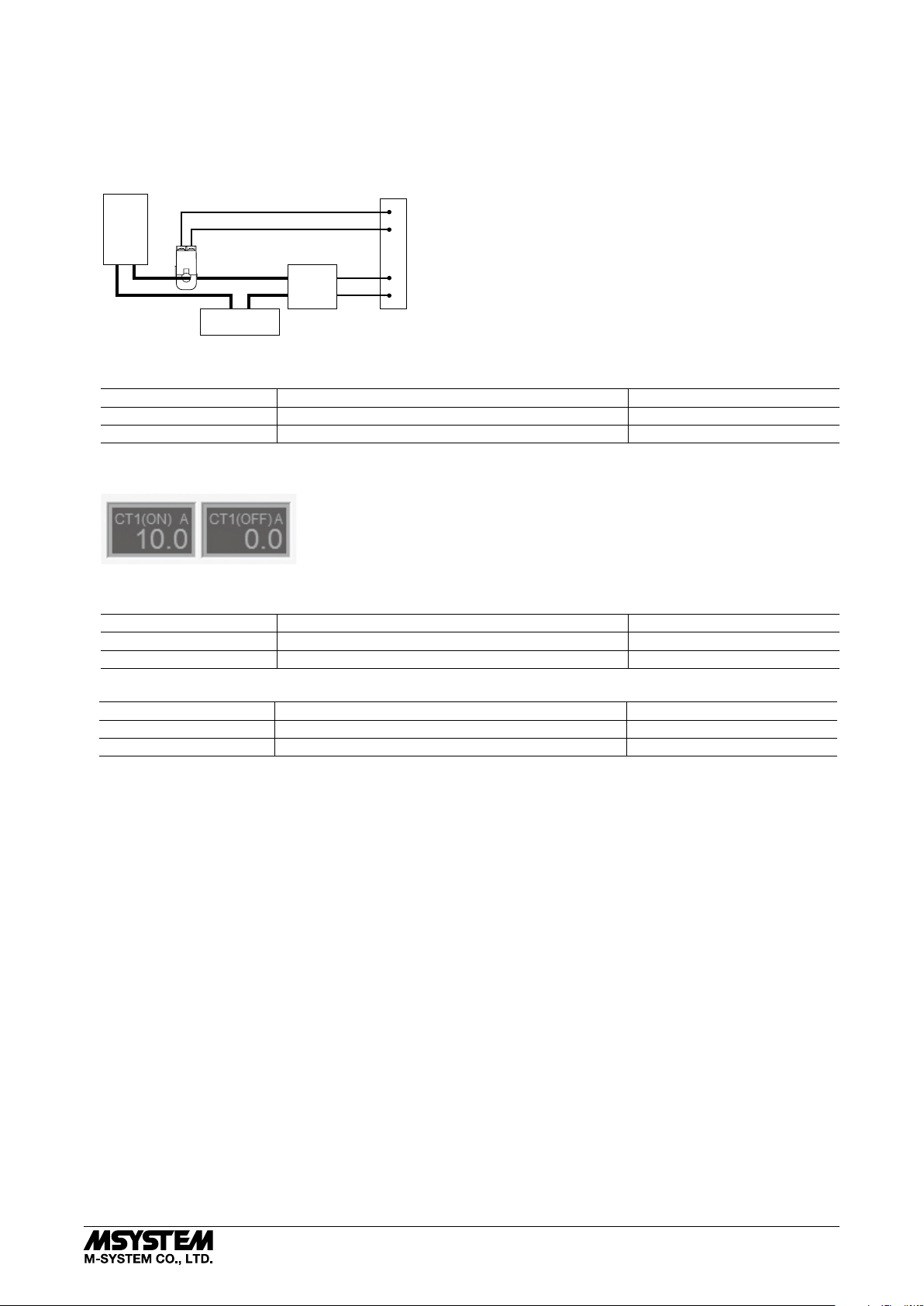
■ SETTING EXAMPLE 2: HEATER WIRE BREAK
In addition to the setting example 1 configuration, the heater’s wire break can be detected using a CT input. Suppose that the
heater has 100V / 1kW rating, driven by an SSR.
(1) Current flowing through the heater is calculated in the equation: 1kW / 100V = 10A. Choose the current sensor model
CLSE-05, for the maximum of 50A rating. Connect the sensor to CT input 1 as in the figure below.
Heater
CLSE-05
SSR
Power Supply
CT Input 1
Control Output 1
R3-TC2
(2) Go to the setting items tree and change the following parameters.
SETTING ITEMS TREE PARAMETER SELECTION
CT input 1 CT sensor type CLSE-05
CT input 1 Output assignment Control output 1
(3) Once the above setting is complete, the Controller measures current values of the control output 1 at ON and OFF states.
The CT1(ON) display shows (approx.) 10A and the CT1(OFF) display shows (approx.) 0.0A.
(4) Set a threshold for the heater wire break.
Set to 5.0A, a value half the rating (approx. 10.0A).
SETTING ITEMS TREE PARAMETER SELECTION
CT input 1 Heater wire break alarm Enable
CT input 1 Heater wire break alarm setpoint 5.0
(5) Set also the following items if the wire break should be alerted at the control output 3 (open collector).
SETTING ITEMS TREE PARAMETER SELECTION
CT input 1 Heater wire break alarm output Control output 3
Control output 3 Output assignment Alarm OR
Now the heater wire break alarm setting is complete.
5-2-55, Minamitsumori, Nishinari-ku, Osaka 557-0063 JAPAN
Phone: +81(6)6659-8201 Fax: +81(6)6659-8510 E-mail: info@m-system.co.jp
EM-8468 Rev.3 P. 10 / 37
Page 11
R3-TC2
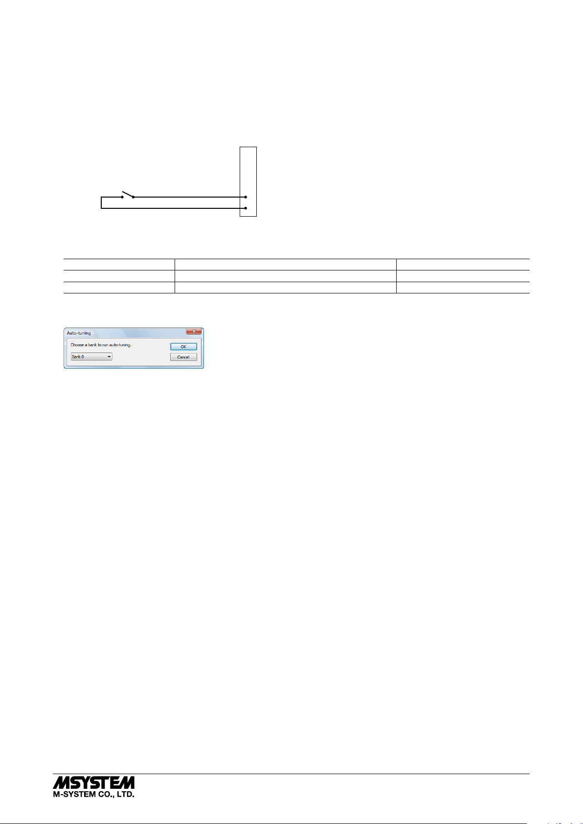
■ SETTING EXAMPLE 3: SWITCHING SETPOINT VALUE BY EVENT INPUT
The Controller has two discrete inputs for event control input.
At the maximum of four sets of temperature setpoints and PID parameters can be predefined and stored in the ‘banks.’ The
external event input can be used to switch among these banks.
In this example, the Controller is set according to the example 1 for the setpoint 40.0°C. By using banks, an additional setting
to switch the setpoint to 50.0°C by an event input is created.
(1) Connect a switch to the discrete input 1 as shown below.
Di 1
R3-TC2
(2) Go to the setting items tree and change the following parameters.
SETTING ITEMS TREE PARAMETER SELECTION
Loop 1, Bank 1 SP (setpoint value) 50.0
Event input Event input 1 function assignment Loop 1, Bank bit 0
(3) Click Auto-tuning button located below the trend graph to show the Auto-tuning dialog box. Choose Bank 1 and click OK.
The Controller go through auto-tuning and then starts control operations.
Now the setting is complete to switch the temperature setpoint to 50.0°C with the switch closed (ON) and to 40.0°C with the
same opened (OFF).
5-2-55, Minamitsumori, Nishinari-ku, Osaka 557-0063 JAPAN
Phone: +81(6)6659-8201 Fax: +81(6)6659-8510 E-mail: info@m-system.co.jp
EM-8468 Rev.3 P. 11 / 37
Page 12

R3-TC2
MODBUS COMMUNICATION
■ R3 I/O DATA
The Controller functions as an analog input module in the R3 remote I/O system. The following 8 words of analog input data
can be read out at Input Register area.
+0
+1
+2
+3
+4
+5
+6
+7
Loop 1 PV (number of decimal places as specified with the ‘input 1 decimal’)
Loop 1 SP (number of decimal places as specified with the ‘input 1 decimal’)
Loop 1 Heating MV (0.01% increments)
Loop 1 Cooling MV (0.01% increments)
Loop 2 PV (number of decimal places as specified with the ‘input 2 decimal’)
Loop 2 SP (number of decimal places as specified with the ‘input 2 decimal’)
Loop 2 Heating MV (0.01% increments)
Loop 2 Cooling MV (0.01% increments)
■ R3 EXTENSION AREA COMMUNICATION
The Controller is compatible with the R3 extension area communication.
By using the model R3-NM3 Modbus Extension Network Module, a large volume of its data can be read out and written in
from the Modbus host device via Holding Register area.
■ EXTENSION AREA ADDRESS ASSIGNMENTS
A Holding Register area of 3000 words is assigned per I/O module as shown in the table below.
SLOT ADDRESS
1 2001 through 5000
2 5001 through 8000
3 8001 through 11000
4 11001 through 14000
: :
15 44001 through 47000
16 47001 through 50000
■ READING EXAMPLE
In order to read the MV value in the table below from the R3-TC2 in the slot position 2, read 1 word at the address 5005, slot
2 top address 5001 added with 4.
ADDRESS PARAMETER UNIT
+4 Loop 1, Heating MV (control output) 0.01%
If 7510 is read, the register value is converted into actual engineering unit value by the following equation:
7510 × 0.01 = 75.10%
■ WRITING EXAMPLE
In order to write 40.0 at the SP value in the table below of the R3-TC2 in the slot position 3, write 400 (when the input 1
decimal is set to ‘1,’ disregard the decimal point) at the address 9153, slot 3 top address 8001 added with 1152.
ADDRESS PARAMETER RANGE DEFAULT
+1152 Loop 1, SP (setpoint) -3200.0 to +3200.0
(decimal by input 1 decimal setting)
25.0
With the decimal setting ‘2,’ write in ‘4000’ for ‘40.00.’
With the setting ‘3,’ ‘40000’ cannot be written as the maximum range is limited up to 32000.
5-2-55, Minamitsumori, Nishinari-ku, Osaka 557-0063 JAPAN
Phone: +81(6)6659-8201 Fax: +81(6)6659-8510 E-mail: info@m-system.co.jp
EM-8468 Rev.3 P. 12 / 37
Page 13

R3-TC2
■ READING
The following parameters can be read out. Address column shows offsets from the top address of the R3 Extension Area Communication.
ADDRESS PARAMETER UNIT
+0 Loop 1, Status 1 (See the table below) ---
+1 Loop 1, Status 2 (See the table below) ---
+2 Loop 1, PV (present value)
+3 Loop 1, Internal SP (setpoint value)
+4 Loop 1, Heating MV (control output) 0.01%
+5 Loop 1, Cooling MV (control output) 0.01%
+6 Loop 1, Local SP (setpoint value)
+7 Loop 1, Remote SP (setpoint value)
+8 Loop 2, Status 1 (See the table below) ---
+9 Loop 2, Status 2 (See the table below) ---
+10 Loop 2, PV (present value)
+11 Loop 2, Internal SP (setpoint value)
+12 Loop 2, Heating MV (control output) 0.01%
+13 Loop 2, Cooling MV (control output) 0.01%
+14 Loop 2, Local SP (setpoint value)
+66 CT input 1, Current value 0.1A
+67 CT input 1, Current value at the control output ON *
+68 CT input 1, Current value at the control output OFF *
¹
1
+69 CT input 2, Current value 0.1A
+70 CT input 2, Current value at the control output ON *
+71 CT input 2, Current value at the control output OFF *
1
1
*1. ‘-1’ (-0.1A) is set when the Controller is unable to measure if the relevant control output does not remain ON or OFF for
the defined time duration in a control cycle. No CT alarm is judged in this case.
Input 1 decimal setting
Input 1 decimal setting
Input 1 decimal setting
Input 1 decimal setting
Input 2 decimal setting
Input 2 decimal setting
Input 2 decimal setting
0.1A
0.1A
0.1A
0.1A
Status 1 and Status 2 are assigned with the following status indicators.
BIT STATU S PARAMETER DATA 0 DATA 1
LSB
0 RUN Loop operating condition STOP RUN
1 AUTO Loop control mode MANUAL AUTO
2 RSP Local / Remote SP selection Local SP Remote SP
3 SP_LAMP SP lamp operation Not operating Operating
4 AT Auto-tuning Not running Running
5 POUT_12 *
Loop 1 status: Control output 1
OFF ON
2
Loop 2 status: Control output 2
6 POUT_34 *
Loop 1 status: Control output 3
OFF ON
2
Loop 2 status: Control output 4
7 INP_ERR Input error Normal Error
STATUS 1
8 INP_R_ERR Remote SP input error Normal Error
9 ALM_HB Heater wire break alarm Normal Alarm
10 ALM_SB SSR shortcircuit failure alarm Normal Alarm
11 ALM_OC Overload alarm Normal Alarm
12 --- --- --- ---
13 ALM_PV1 PV 1 alarm Normal Alarm
14 ALM_PV2 PV 2 alarm Normal Alarm
MSB
15 ALM_PV3 PV 3 alarm Normal Alarm
LSB 0 EV1 Event input 1 OFF ON
1 EV2 Event input 2 OFF ON
2 BANK0 Bank bit 0 OFF ON
STATUS 2
3 BANK1 Bank bit 1 OFF ON
*2. Control outputs 1 and 3 are read out at Loop 1 status, Control output 2 and 4 are read at Loop 2 status regardless of the
output assignment setting. These bits is always at ‘1’ (ON) with DC output.
5-2-55, Minamitsumori, Nishinari-ku, Osaka 557-0063 JAPAN
Phone: +81(6)6659-8201 Fax: +81(6)6659-8510 E-mail: info@m-system.co.jp
EM-8468 Rev.3 P. 13 / 37
Page 14

R3-TC2
■ SETPOINT VALUE SETTING
SP for each loop can be changed via Modbus.
ADDRESS PARAMETER RANGE DEFAULT
+6 Loop 1, Local SP (setpoint value) -3200.0 to +3200.0
+14 Loop 2, Local SP (setpoint value)
decimal by input 1/2 decimal setting
(
)
These registers are overwritten by the SP in bank setting when the power supply is turned off or when the bank is switched.
Write the SP in the bank setting if the values should be maintained.
■ COMMAND EXECUTION
Predefined commands for each loop can be issued via Modbus by writing in the following addresses.
ADDRESS PARAMETER RANGE DEFAULT
+64 Loop 1, Command See the table below. ---
+65 Loop 2, Command
Available commands are as in the table below:
COMMAND PARAMETER
1 Set loop operation to RUN
2 Set loop operation to STOP
3 Set control mode to AUTO
4 Set control mode to MANUAL
8 Reset all latched alarms in the loop
9 Reset all latched PV alarms
10 Reset all latched CT alarms
16 Switch to Bank 0
17 Switch to Bank 1
18 Switch to Bank 2
19 Switch to Bank 3
24 Run auto-tuning in the conditions specified by Bank 0
25 Run auto-tuning in the conditions specified by Bank 1
26 Run auto-tuning in the conditions specified by Bank 2
27 Run auto-tuning in the conditions specified by Bank 3
---
Loop operation, control mode and bank switching operation can be executed by an event input, however, using both commands
and event inputs may cause an unexpected result. We recommend that a function assigned to an event input be not controlled
by a command.
SETTING
■ SETTING CHANGE VIA MODBUS
Reading and writing via Modbus from the host is possible by the Network Module (model: R3-NM3).
Parameters are listed with Modbus address and data size in this manual. Access Holding Registers at these addresses to read
and write to refer and change settings.
Refer to “COMMUNICATION” section for the procedure.
5-2-55, Minamitsumori, Nishinari-ku, Osaka 557-0063 JAPAN
Phone: +81(6)6659-8201 Fax: +81(6)6659-8510 E-mail: info@m-system.co.jp
EM-8468 Rev.3 P. 14 / 37
Page 15
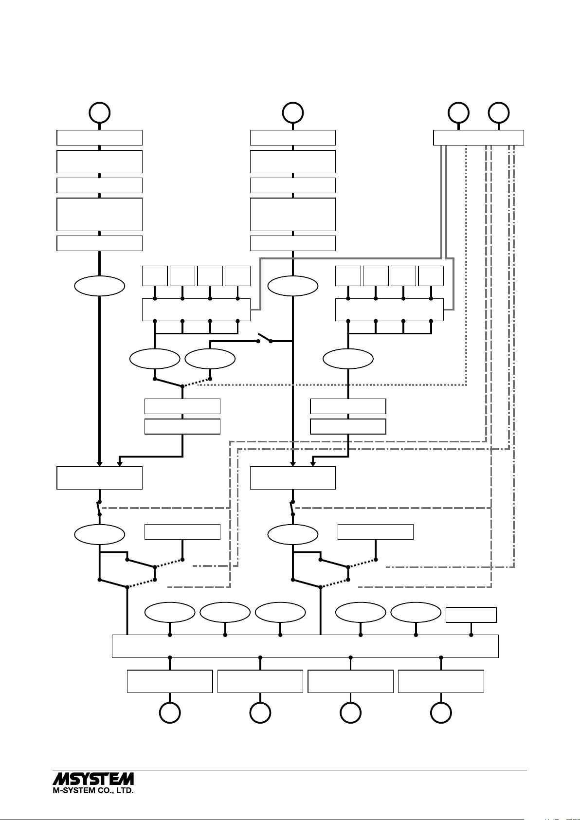
■ FUNCTION BLOCK DIAGRAM
The figure below is a simplified function block diagram showing relations between the I/O signal and the setting.
R3-TC2
Universal Input 1
PV1
Input type
Input zero adjustment
Input span adjustment
Temperature unit
Input 0%, 100%
Input scaling 0%, 100%
Decimal
Filter time constant
Input 1 PV
Bank 1SPBank 2SPBank 3SPBank 4
Bank Switching
Local SP1
Remote SP1
Universal Input 2
Input type
Input zero adjustment
Input span adjustment
Temperature unit
Input 0%, 100%
Input scaling 0%, 100%
Filter time constant
SP
Input 2 PV
Remote SP
PV2
Decimal
Bank 1SPBank 2SPBank 3SPBank 4
Bank Switching
Local SP2
Event Input 1, 2
Di1
Event Input Assignment
BANK SWITCHING
LOCAL SP / REMOTE SP
SP
Di2
AUTO / MANUAL
RUN / STOP
Loop 1
PID or ON/OFF control
AUTO
Loop 1 MV
RUN
MANUAL
SP high/low limit
SP ramp
MV value at STOP
STOP
AUTO
Input 1 PV Local SP1 Remote SP1
Output 0%, 100%
Output scaling 0%, 100%
Output 0%, 100%
Output scaling 0%, 100%
Loop 2
PID or ON/OFF control
AUTO
Loop 2 MV
RUN
MANUAL
Output Assignment
Output scaling 0%, 100%
SP high/low limit
SP ramp
MV value at STOP
STOP
AUTO
Input 2 PV Local SP2
Output 0%, 100%
Alarm
Output 0%, 100%
Output scaling 0%, 100%
MV1
Control Output 1
5-2-55, Minamitsumori, Nishinari-ku, Osaka 557-0063 JAPAN
Phone: +81(6)6659-8201 Fax: +81(6)6659-8510 E-mail: info@m-system.co.jp
MV2
Control Output 2
Do1
Control Output 3
Do2
Control Output 4
EM-8468 Rev.3 P. 15 / 37
Page 16

R3-TC2
UNIVERSAL INPUT
The Controller has two universal inputs (universal input 1, universal input 2) which can be assigned independently for temperature inputs. In addition to RTD and thermocouples, resistor, DC and potentiometer inputs are also usable. The resistor,
DC and potentiometer input is scaled into a temperature range.
Universal input 1 is usually assigned as PV input signal for loop 1, while universal input 2 is for loop 2. Universal input 2
signal can be cascaded into the loop 1 SP.
• DC Voltage (-10 – +10V DC)
• DC Current (0 – 20mA DC)
• DC Voltage (-1000 – +1000mV DC)
INPUT
• Thermocouple
–
–
CJC
+
SENSOR
comp. leadwire
• RTD / Resistor (3-wire)
A
B
B
• RTD / Resistor (2-wire)
A
B
• Potentiometer
max.
min.
Universal Input 1
Universal Input 2
Loop 1
Loop 2
■ INPUT TYPE
ADDRESS PARAMETER RANGE DEFAULT
+128 Universal input 1, Input type See the table below. 10
+384 Universal input 2, Input type
SET VALUE
0
1
2
3
4
5
6
7
8
9
10
14
15
16
17
DC 0 − 20mA
DC -1000 − +1000mV
DC -10 − +10V
POT 0 − 4000Ω
POT 0 − 2500Ω
POT 0 − 1200Ω
POT 0 − 600Ω
POT 0 − 300Ω
POT 0 − 150Ω
Resistor 0 − 4000Ω
RTD Pt 100
RTD Pt 500
RTD Pt 1000
RTD Pt 50Ω
RTD JPt 100
PARAMETER
SET VALUE
20
22
24
25
26
27
28
29
30
31
32
33
34
35
36
PARAMETER
RTD Ni 508.4Ω
RTD Cu 10
TC (PR)
TC K
TC E
TC J
TC T
TC B
TC R
TC S
TC C
TC N
TC U
TC L
TC P
5-2-55, Minamitsumori, Nishinari-ku, Osaka 557-0063 JAPAN
Phone: +81(6)6659-8201 Fax: +81(6)6659-8510 E-mail: info@m-system.co.jp
EM-8468 Rev.3 P. 16 / 37
Page 17

R3-TC2
■ WIRING
Choose either 2 wires or 3 wires when the input type is set to RTD or resistor.
ADDRESS PARAMETER RANGE DEFAULT
+129 Universal input 1, Wiring 0 : 2 wires
+385 Universal input 2, Wiring
1 : 3 wires
■ BURNOUT
Choose burnout function when the input type is set to thermocouple, RTD, resistor or potentiometer.
ADDRESS PARAMETER RANGE DEFAULT
+130 Universal input 1, Burnout 0 : Disable
+386 Universal input 2, Burnout
1 : Enable
1
■ COLD JUNCTION COMPENSATION
Choose cold junction compensation by the cold junction temperature sensor included in the product package for thermocouple
input.
When the setting is disabled, the terminal temperature is assumed to show 0°C so that the measured emf is directly converted
into temperature.
ADDRESS PARAMETER RANGE DEFAULT
+131 Universal input 1, Cold junction compensation 0 : Disable
+387 Universal input 2, Cold junction compensation
1 : Enable
1
1
■ TEMPERATURE UNIT
Choose temperature unit used for thermocouple or RTD input.
The setting is applied only to the unit, but not to the temperature values such as SP. If you have changed the unit setting, be
sure to check and change all other temperature values.
ADDRESS PARAMETER RANGE DEFAULT
+132 Universal input 1, Temperature unit 0 : degC
+388 Universal input 2, Temperature unit
1 : degF
0
■ INPUT ZERO ADJUSTMENT / INPUT SPAN ADJUSTMENT
Input signals can be finely adjusted.
The following equation is applied to the engineering unit value data.
[Adjusted value] = [input] × [input span adjustment] + [input zero adjustment]
ADDRESS PARAMETER RANGE DEFAULT
+133 Universal input 1, Input zero adjustment -300.00 to +300.00
+389 Universal input 2, Input zero adjustment
+134 Universal input 1, Input span adjustment 0.8500 to 1.1500 1.0000
+390 Universal input 2, Input span adjustment
INPUT TYPE UNIT
0 − 20mA DC mA
-1000 − +1000mV DC mV
-10 − +10V DC V
Thermocouple mV
RTD, Resistor Ω
Potentiometer %
(unit as in the table below)
0.00
5-2-55, Minamitsumori, Nishinari-ku, Osaka 557-0063 JAPAN
Phone: +81(6)6659-8201 Fax: +81(6)6659-8510 E-mail: info@m-system.co.jp
EM-8468 Rev.3 P. 17 / 37
Page 18

R3-TC2
■ INPUT 0% / INPUT 100% / INPUT SCALING 0% / INPUT SCALING 100%
DC, resistor and potentiometer input signals can be converted into a temperature range.
Specify the original input range from INPUT 0% to INPUT 100%, and the converted range from INPUT SCALING 0% to
INPUT SCALING 100%.
ADDRESS PARAMETER RANGE DEFAULT
+135 Universal input 1, Input 0% -1000.0 to +4000.0 *3
+136 Universal input 1, Input 100% 20.0
+137 Universal input 1, Input scaling 0% -3200.0 to +3200.0
+138 Universal input 1, Input scaling 100% 100.0
+391 Universal input 2, Input 0% -1000.0 to +4000.0 *3
+392 Universal input 2, Input 100% 20.0
+393 Universal input 2, Input scaling 0% -3200.0 to +3200.0
+394 Universal input 2, Input scaling 100% 100.0
(unit as in the table below)
(decimal by input 1 decimal setting)
(unit as in the table below)
(decimal by input 2 decimal setting)
*3. Signed words have the maximum range up to +32767. +32768 to +40000 is internally converted into -32768 to -25536 so
that the entire range up to 40000 can be within the normal range limits.
INPUT TYPE UNIT
0 − 20mA DC mA
-1000 − +1000mV DC mV
-10 − +10V DC V
Resistor Ω
Potentiometer %
4.0
0.0
4.0
0.0
■ FILTER TIME CONSTANT
First order lag filter can be applied to the input signal. Time constant setting is available from 0.5 to 60.0 seconds. Setting
0.0 disables the filter function.
The filter operates just like a typical CR filter. With a step input, the filter output takes the preset time constant time to reach
63% value.
ADDRESS PARAMETER RANGE DEFAULT
+139 Universal input 1, Filter time constant 0.0, 0.5 to 60.0 seconds 0.0
+395 Universal input 2, Filter time constant
■ DECIMAL
Choose the number of decimal places for PV (input) signal.
The setting affects the input and relevant loop, and the output setting assigned to its loop’s control output.
Those parameters affected by the setting are indicated with ‘decimal by input 1 decimal setting’ or ‘decimal by input 2 decimal
setting.’
ADDRESS PARAMETER RANGE DEFAULT
+140 Universal input 1, Decimal 0, 1, 2, 3 (digits) 1
+396 Universal input 2, Decimal
PV and relevant ranges may be limited as shown in the table below depending upon the decimal setting.
DECIMAL RANGE
0 -32000 − +32000
1 -3200.0 − +3200.0
2 -320.00 − + 320.00
3 -32.000 − +32.000
Related ranges are not automatically scaled when the setting is changed. Be sure to check and change all other values.
5-2-55, Minamitsumori, Nishinari-ku, Osaka 557-0063 JAPAN
Phone: +81(6)6659-8201 Fax: +81(6)6659-8510 E-mail: info@m-system.co.jp
EM-8468 Rev.3 P. 18 / 37
Page 19

R3-TC2
CONTROL OUTPUT
The Controller has four control outputs (control output 1 through 4) which are assigned to control output, alarm output and
other outputs.
Basic output channel configuration is determined by the model number suffix codes as shown below.
Control output 1, Control output 2 R3-TC2Ax 0 − 20mA DC output
R3-TC2Vx 0 − 10V DC output
R3-TC2Px 12V pulse output
Control output 3, Control output 4 Open collector output
Each output channel can be assigned with alarm output (ON/OFF) or with control output (continuous value) as explained in
the table below.
OUTPUT ON/OFF CONTINUOUS VALUE
0 − 20mA DC ON at 100% scaled current; OFF at 0%
scaled current
0 − 10V DC ON at 100% scaled voltage; OFF at 0%
scaled voltage
12V pulse ON at 12V; OFF at 0V Scaled output range is converted into a
Open collector ON at closed state; OFF at open state Scaled output range is converted into a
Scaled output range is converted into a
proportional current range
Scaled output range is converted into a
proportional voltage range
proportional duty ratio output
proportional duty ratio output
■ OUTPUT ASSIGNMENT
ADDRESS PARAMETER RANGE DEFAULT
+1280 Control output 1, Output assignment See the table below. 16
+1440 Control output 2, Output assignment 32
+1600 Control output 3, Output assignment 16
+1760 Control output 4, Output assignment 32
SET VALUE
0 Not assigned --- ----
1 Device error ON/OFF ----
2 Alarm OR ON/OFF ----
3 Alarm AND ON/OFF ----
4 Input error, OR for all loops ON/OFF ----
16 Loop 1, Heating control output Continuous value 2
17 Loop 1, Cooling control output Continuous value 2
18 Loop 1, PV Continuous value By input 1 decimal setting
19 Loop 1, Internal SP Continuous value By input 1 decimal setting
20 Loop 1, Local SP Continuous value By input 1 decimal setting
21 Loop 1, Remote SP Continuous value By input 1 decimal setting
22 Loop 1, Input error ON/OFF ----
23 Loop 1, Remote SP input error ON/OFF ----
32 Loop 2, Heating control output Continuous value 2
33 Loop 2, Cooling control output Continuous value 2
34 Loop 2, PV Continuous value By input 2 decimal setting
35 Loop 2, Internal SP Continuous value By input 2 decimal setting
36 Loop 2, Local SP Continuous value By input 2 decimal setting
38 Loop 2, Input error ON/OFF ---
PARAMETER TYPE OUTPUT SCALING DECIMAL
5-2-55, Minamitsumori, Nishinari-ku, Osaka 557-0063 JAPAN
Phone: +81(6)6659-8201 Fax: +81(6)6659-8510 E-mail: info@m-system.co.jp
EM-8468 Rev.3 P. 19 / 37
Page 20

R3-TC2
■ CONTROL CYCLE
Specify duty cycle for duty ratio output. Disregarded with DC signal output setting.
ADDRESS PARAMETER RANGE DEFAULT
+1281 Control output 1, Control cycle 1.0 to 99.9 seconds 2.0
+1441 Control output 2, Control cycle
+1601 Control output 3, Control cycle
+1761 Control output 4, Control cycle
■ MINIMUM ON/OFF WIDTH
Specify the minimum pulse width for ON and OFF with duty ratio output.
For example, with 1% setting, the output below 1% is output as 0%, while the output above 99% is output as 100%.
ADDRESS PARAMETER RANGE DEFAULT
+1282 Control output 1, Minimum ON/OFF width 0.0 to 50.0 % 0.0
+1442 Control output 2, Minimum ON/OFF width
+1602 Control output 3, Minimum ON/OFF width
+1762 Control output 4, Minimum ON/OFF width
■ OUTPUT SCALING 0% / OUTPUT SCALING 100%
Scales and outputs the assigned output value.
ADDRESS PARAMETER RANGE DEFAULT
+1283 Control output 1, Output scaling 0% *
+1284 Control output 1, Output scaling 100% *
+1443 Control output 2, Output scaling 0% *
+1444 Control output 2, Output scaling 100% *
+1603 Control output 3, Output scaling 0% *
+1604 Control output 3, Output scaling 100% *
+1763 Control output 4, Output scaling 0% *
+1764 Control output 4, Output scaling 100% *
*4. Output scaling 0 to 100% is valid only when control output is assigned to PV, Internal SP, Local SP or Remote SP on setting
“OUTPUT ASSIGNMENT”. Disregarded if it is assigned to others.
Output scaling 0% of control output 1 is PV (input value) or SP (target value) at which the control output 1 output becomes 0%.
Output scaling 100% of control output 1 is PV (input value) or SP (target value) at which the control output 1 output becomes
100%.
The same applies to control output 2, control output 3, control output 4.
e.g. If the “OUTPUT ASSIGNMENT” setting is “Loop 1 PV”, as it follows.
If output scaling 0% of control output 1 become 20,
at that time PV of Loop 1 is 20, control output 1 outputs 0%.
If output scaling 100% of control output 1 become 80,
at that time PV of Loop 1 is 80, control output 1 outputs 100%.
*5. Refer to the “DECIMAL” about digits setting
4
4
4
4
4
4
4
4
-3200.0 to +3200.0
(Input 1 decimal digits unit or
Input 2 decimal digits unit) *5
0.0
100.0
0.0
100.0
0.0
100.0
0.0
100.0
■ OUTPUT 0% / OUTPUT 100%
When output control is 0%, output 0% is setting the value of output from the terminal block of unit.
When output control is 100%, output 100% is setting the value of output from the terminal block of unit.
ADDRESS PARAMETER RANGE DEFAULT
+1285 Control output 1, Output 0% 0.0 to 100.0 *6
+1286 Control output 1, Output 100%
+1445 Control output 2, Output 0%
+1446 Control output 2, Output 100%
+1605 Control output 3, Output 0% 0.0 to 100.0% 0.0
+1606 Control output 3, Output 100% 100.0
+1765 Control output 4, Output 0% 0.0
+1766 Control output 4, Output 100% 100.0
*6. Default value and engineering unit depends upon the model number suffix code as in the table below.
MODEL DEFAULT(OUTPUT 0%) DEFAULT(OUTPUT 100%) UNIT
R3-TC2Ax 4.0 20.0 mA
R3-TC2Vx 0.0 10.0 V
R3-TC2Px 0.0 100.0 %
5-2-55, Minamitsumori, Nishinari-ku, Osaka 557-0063 JAPAN
Phone: +81(6)6659-8201 Fax: +81(6)6659-8510 E-mail: info@m-system.co.jp
EM-8468 Rev.3 P. 20 / 37
Page 21

R3-TC2
■ OUTPUT INVERSION
12 V pulse signal level and open collector output ON/OFF logic can be inverted.
ADDRESS PARAMETER RANGE DEFAULT
+1287 Control output 1, Output inversion 0 : Normal
+1447 Control output 2, Output inversion
+1607 Control output 3, Output inversion
+1767 Control output 4, Output inversion
1 : Inverted
0
LOOP
The Controller has two control loops (loop 1, loop 2) which can be assigned independently with PID and ON/OFF control
operations.
Each loop receives the relevant input to feedback and perform temperature control.
■ OPERATION AT STARTUP
Specify whether the Controller automatically starts operating (RUN) or not (STOP). With STOP setting, it outputs the predefined ‘MV output at STOP status.’
ADDRESS PARAMETER RANGE DEFAULT
+192 Loop 1, Operation at startup 0 : STOP
+448 Loop 2, Operation at startup
1 : RUN
0
■ CONTROL MODE AT STARTUP
Specify the control mode at the startup. In MANUAL mode, the control output can be manually manipulated. In AUTO mode,
the Controller starts automatic control operations.
ADDRESS PARAMETER RANGE DEFAULT
+193 Loop 1, Control mode at startup 0 : MANUAL
+449 Loop 2, Control mode at startup
1 : AUTO
0
5-2-55, Minamitsumori, Nishinari-ku, Osaka 557-0063 JAPAN
Phone: +81(6)6659-8201 Fax: +81(6)6659-8510 E-mail: info@m-system.co.jp
EM-8468 Rev.3 P. 21 / 37
Page 22

R3-TC2
proportional
MV
■ CONTROL TYPE
Specify the control strategy for each loop.
ADDRESS PARAMETER RANGE DEFAULT
+194 Loop 1, Control type 0 : Standard PID control
+450 Loop 2, Control type
1 : Heating-cooling PID control
2 : Heating-cooling ON/OFF control
• Standard PID Control
Typical PID control operation is performed by PID1 P (proportional band), PID1 I (integral time) and PID1 D (derivative time)
set in the selected bank. The Controller automatically adjusts the heating control output (MV) to match the setpoint value
(SP) with the universal input value (PV).
• Heating-Cooling PID Control
PID control is applied to both heating and cooling using PID parameters in PID1 (for heating) and PID2 (for cooling) parameters.
PARAMETER DESCRIPTIONS SMALLER SET VALUE LARGER SET VALUE
P
proportional band
(
P output is proportional to the deviation
)
between the input (PV) and the setpoint
(SP).
100%
band
• Takes shorter time to reach
the target temperature
• Overshooting or cycling
may occur more frequently.
• Takes longer time to reach
the target temperature
• Overshooting is unlikely to
occur.
0
SP
PV
• Takes shorter time to reach
the target temperature
• Overshooting, undershooting, or cycling may occur to
a greater degree.
• Overshooting or undershooting may occur to a
greater degree.
• Takes longer time to reach
the target temperature
• Overshooting, undershooting, or cycling may be
diminished.
• Overshooting or undershooting may be diminished.
• Small hunting may occur.
I
(integral time)
D
(derivative time)
50%
0%
I output is proportional to the integrated
deviation between PV and SP.
It is used to automatically adjust offset by
P output.
D output is proportional to the derivative of
deviation between PV and SP.
It is used as a corrective action against
changes in PV and SP.
• Heating-Cooling ON/OFF Control
The control output is turned on until the universal input (PV) matches the setpoint value (SP) and then turned off. Heating
control is applied when the SP is greater than the PV, while cooling control is applied when the SP is smaller than the PV.
The output is turned on again if the PV is deviated from the SP again, but the sensitivity to react to a deviation can be set for
heating and cooling respectively.
heating control output
ON
OFF
heating sensitivity cooling sensitivity
cooling control output
SP
PV
■ DIRECT/REVERSE ACTION
Direct or reverse action can be specified for the standard PID control.
Choose ‘reverse’ action when the MV should be decreased with an increasing PV (typical heating control), and ‘direct’ action
when the MV should be increased (typical cooling control).
Disregarded if the selected control strategy is other than the standard PID control.
ADDRESS PARAMETER RANGE DEFAULT
+195 Loop 1, Direct/reverse action 0 : Reverse
+451 Loop 2, Direct/reverse action
1 : Direct
0
5-2-55, Minamitsumori, Nishinari-ku, Osaka 557-0063 JAPAN
Phone: +81(6)6659-8201 Fax: +81(6)6659-8510 E-mail: info@m-system.co.jp
EM-8468 Rev.3 P. 22 / 37
Page 23

■ REMOTE SP
Input 2 signal can be cascaded into Input 1 setpoint value as Remote SP.
ADDRESS PARAMETER RANGE DEFAULT
+196 Loop 1, Remote SP 0 : Disable
1 : Enable
Remote SP operates as in the function diagram below.
Local and remote SP are switched by an event input. If no event input is assigned, only the remote SP is used.
R3-TC2
0
Input 1
PV
Loop 1
Selected Bank SP
Local SP
Event Input
Internal SP
Loop 1 Control
Remote SP
Remote SP
Input 2
PV
Loop 2 Control
Loop 2
Selected Bank SP
Local SP
Internal SP
*
* Loop 2 control is not available while loop 1 remote SP is enabled.
■ SP TRACKING
Specify whether the remote SP should be carried on when it is switched to the local SP mode.
ADDRESS PARAMETER RANGE DEFAULT
+197 Loop 1, SP tracking 0 : Disable
1 : Enable
■ SP LOW LIMIT / SP HIGH LIMIT
Specify the lower and the upper limits for the SP.
For example, if the SP range is set to 0.0 − 100.0, setting 100.0 is used for setting 200.0 automatically.
ADDRESS PARAMETER RANGE DEFAULT
+198 Loop 1, SP low limit -3200.0 to +3200.0
+199 Loop 1, SP high limit 3200.0
(decimal by input 1 decimal setting)
+454 Loop 2, SP low limit -3200.0 to +3200.0
+455 Loop 2, SP high limit 3200.0
(decimal by input 2 decimal setting)
-3200.0
-3200.0
0
5-2-55, Minamitsumori, Nishinari-ku, Osaka 557-0063 JAPAN
Phone: +81(6)6659-8201 Fax: +81(6)6659-8510 E-mail: info@m-system.co.jp
EM-8468 Rev.3 P. 23 / 37
Page 24

R3-TC2
■ MV AT STARTUP / MV AT STOP / MV AT ERROR
Specific MV values can be set for respective loop status.
ADDRESS PARAMETER RANGE DEFAULT
+200 Loop 1, MV at startup -105.00 to +105.00 % 0.00
+201 Loop 1, MV at STOP
+202 Loop 1, MV at error
+456 Loop 2, MV at startup
+457 Loop 2, MV at STOP
+458 Loop 2, MV at error
With standard PID control, -5.00 is used for any value below -5.00.
With heating-cooling PID control, negative value is applied for cooling control.
With ON/OFF control, cooling control is turned on at -100.00, both cooling and heating is off at 0.00, and heating is on at
100.00.
With MANUAL control mode, the MV at startup is applied at the startup, however, once the Controller transits from AUTO
to MANUAL, the MV value at the moment of the transition is carried on.
The Controller’s action is determined in the following priority order: MANUAL > STOP > Error.
■ MV LOW LIMIT / MV HIGH LIMIT
Specify the lower and the upper limits for the MV.
For example, if the MV range is set to 0.00 − 50.00, setting 50.00 is used for setting 70.00 automatically.
ADDRESS PARAMETER RANGE DEFAULT
+203 Loop 1, MV low limit -105.00 to +105.00 % -100.00
+204 Loop 1, MV high limit 100.00
+459 Loop 2, MV low limit -100.00
+460 Loop 2, MV high limit 100.00
■ ERROR ACTION
Specify the Controller’s action in case of an input error (burnout) or an error in the remote SP input.
ADDRESS PARAMETER RANGE DEFAULT
+205 Loop 1, Error action 0 : Operation continued
+461 Loop 2, Error action
1 : ‘MV at error’ output
2 : STOP
1
With ‘Operation continued’ setting, the Controller continues operating.
With ‘MV at error’ output setting, it outputs the specified output value until the error is cancelled.
With STOP setting, the Controller stops operating. It does not restart automatically even when the error is cancelled.
■ CT ALARM ACTION
Specify the Controller’s action in case of an alarm by CT input (heater wire break, SSR shortcircuit failure or overload).
ADDRESS PARAMETER RANGE DEFAULT
+206 Loop 1, CT alarm action 0 : Operation continued
+462 Loop 2, CT alarm action
1 : ‘MV at error’ output
2 : STOP
1
With ‘Operation continued’ setting, the Controller continues operating.
With ‘MV at error’ output setting, it outputs the specified output value until the error is cancelled.
With STOP setting, the Controller stops operating. It does not restart automatically even when the error is cancelled.
5-2-55, Minamitsumori, Nishinari-ku, Osaka 557-0063 JAPAN
Phone: +81(6)6659-8201 Fax: +81(6)6659-8510 E-mail: info@m-system.co.jp
EM-8468 Rev.3 P. 24 / 37
Page 25

■ PV ALARM 1, PV ALARM 2, PV ALARM 3
The Controller monitors PV signal to trigger alarms in predefined conditions.
Three alarm conditions (PV ALARM 1 through 3) per loop can be specified.
High/low setpoint values can be specified by banks, together with other settings such as SP.
• ALARM TYPE
Specify conditions to be monitored for alarm trip.
ADDRESS PARAMETER RANGE DEFAULT
+320 Loop 1, Alarm 1 type See the table below. 0
+328 Loop 1, Alarm 2 type
+336 Loop 1, Alarm 3 type
+576 Loop 2, Alarm 1 type
+584 Loop 2, Alarm 2 type
+592 Loop 2, Alarm 3 type
R3-TC2
SET VALUE
0 Alarm OFF
1Deviation Hi/Lo limit
2Deviation Hi limit
3Deviation Lo limit
4Deviation range
5Deviation Hi/Lo limit
with standby sequence
6Deviation Hi limit
with standby sequence
7Deviation Lo limit
with standby sequence
8 Absolute value Hi/Lo limit
ALARM TYPE
Lo
Lo
Lo
Lo
Lo
Lo
SP
SP
SP
SP
SP
SP
SP
Hi
Hi
Hi
Hi
Hi
Hi
alarm range
0
9 Absolute value Hi limit
10 Absolute value Lo limit
11 Absolute value Hi/Lo limit
with standby sequence
12 Absolute value Hi limit
with standby sequence
13 Absolute value Lo limit
with standby sequence
Hi
0
Lo
0
Lo
Hi
0
Hi
0
Lo
0
Standby sequence is a function to prevent unwanted alarm triggered at the startup or at an SP change. If the PV is in alarm
range at the startup or at an SP change, no alarm is triggered until the PV is out of the range. Once it is out and then in the
range again, normal alarm function starts functioning.
5-2-55, Minamitsumori, Nishinari-ku, Osaka 557-0063 JAPAN
Phone: +81(6)6659-8201 Fax: +81(6)6659-8510 E-mail: info@m-system.co.jp
EM-8468 Rev.3 P. 25 / 37
Page 26

R3-TC2
• ALARM HIGH SETPOINT / ALARM LOW SETPOINT
Multiple setpoint values can be specified by using banks. Refer to ‘BANK’ section for assigned addresses.
For the deviation alarm, specify offset values from the SP (positive value for a temperature value greater than the SP, negative value for one smaller).
For the absolute value alarm, specify absolute temperature values.
• ALARM HYSTERESIS
Hysteresis, a deadband between ON point and OFF point, is used to prevent frequent ON/OFF operations (generally called
‘chattering’) of an alarm output device when the PV fluctuates around the setpoint.
alarm hysteresis alarm hysteresis
alarm ON
alarm OFF
ADDRESS PARAMETER RANGE DEFAULT
+321 Loop 1, Alarm 1 hysteresis 0.0 to 999.9
+329 Loop 1, Alarm 2 hysteresis
+337 Loop 1, Alarm 3 hysteresis
+577 Loop 2, Alarm 1 hysteresis 0.0 to 999.9
+585 Loop 2, Alarm 2 hysteresis
+593 Loop 2, Alarm 3 hysteresis
alarm Lo limit alarm Hi limit
0.0
(decimal by input 1 decimal setting)
(decimal by input 2 decimal setting)
• ALARM LATCHING
Once an alarm is tripped, it is held even when the alarm condition is cancelled.
Latched alarm is reset by turning the device’s power supply off or by Modbus command.
ADDRESS PARAMETER RANGE DEFAULT
+322 Loop 1, Alarm 1 latching 0 : Disable
+330 Loop 1, Alarm 2 latching
+338 Loop 1, Alarm 3 latching
+578 Loop 2, Alarm 1 latching
+586 Loop 2, Alarm 2 latching
+594 Loop 2, Alarm 3 latching
1 : Enable
0
• ALARM ON DELAY / ALARM OFF DELAY
Alarm ON delay time is applied to the time during which an alarm condition should remain true, before the alarm trips.
Alarm OFF delay time is applied to the time during which an alarm conditions should remain false, before the tripped alarm
is reset.
Setting 0 means no delay in the alarm operations.
ADDRESS PARAMETER RANGE DEFAULT
+323 Loop 1, Alarm 1 ON delay 0 to 999 seconds 0
+331 Loop 1, Alarm 2 ON delay
+339 Loop 1, Alarm 3 ON delay
+579 Loop 2, Alarm 1 ON delay
+587 Loop 2, Alarm 2 ON delay
+595 Loop 2, Alarm 3 ON delay
+324 Loop 1, Alarm 1 OFF delay
+332 Loop 1, Alarm 2 OFF delay
+340 Loop 1, Alarm 3 OFF delay
+580 Loop 2, Alarm 1 OFF delay
+588 Loop 2, Alarm 2 OFF delay
+596 Loop 2, Alarm 3 OFF delay
5-2-55, Minamitsumori, Nishinari-ku, Osaka 557-0063 JAPAN
Phone: +81(6)6659-8201 Fax: +81(6)6659-8510 E-mail: info@m-system.co.jp
EM-8468 Rev.3 P. 26 / 37
Page 27

R3-TC2
• ALARM SP TYPE
When the SP is changed, actual target temperature gradually changes in a ramp setting until it reaches the final setpoint.
Choose either the setpoint in the ramp transition or the final setpoint should be used for reference of alarm judgment.
ADDRESS PARAMETER RANGE DEFAULT
+325 Loop 1, Alarm 1 SP type 0 : Ramp SP
+333 Loop 1, Alarm 2 SP type
+341 Loop 1, Alarm 3 SP type
+581 Loop 2, Alarm 1 SP type
+589 Loop 2, Alarm 2 SP type
+597 Loop 2, Alarm 3 SP type
1 : SP
• ALARM OUTPUT
Specify the output device for alarms.
When one of the control outputs is specified, be sure also to specify ‘Alarm OR’ or ‘Alarm AND’ with its output assignment.
With ‘Alarm OR’ setting, the output is provided if one or more alarms assigned to it are in true conditions. With ‘Alarm AND’
setting it is provided only if all alarms assigned to it are in true conditions.
ADDRESS PARAMETER RANGE DEFAULT
+326 Loop 1, Alarm 1 output 0 : Network only
+334 Loop 1, Alarm 2 output
+342 Loop 1, Alarm 3 output
+582 Loop 2, Alarm 1 output
+590 Loop 2, Alarm 2 output
+598 Loop 2, Alarm 3 output
1 : Control output 1
2 : Control output 2
3 : Control output 3
4 : Control output 4
0
0
5-2-55, Minamitsumori, Nishinari-ku, Osaka 557-0063 JAPAN
Phone: +81(6)6659-8201 Fax: +81(6)6659-8510 E-mail: info@m-system.co.jp
EM-8468 Rev.3 P. 27 / 37
Page 28

R3-TC2
BANK
The Controller has four sets of banks per loop. Temperature setpoint and PID and other parameters can be stored and
switched easily during operation by an external event input (Di) or via Modbus communication.
Bank 0 is used when there is no bank switching.
■ SP (SETPOINT VALUE)
Specify local SP.
CAUTION
[Bank 0]
ADDRESS PARAMETER RANGE DEFAULT
+1152 Loop 1, SP (setpoint value) -3200.0 to +3200.0
+1792 Loop 2, SP (setpoint value)
[Bank 1]
ADDRESS PARAMETER RANGE DEFAULT
+1312 Loop 1, SP (setpoint value) -3200.0 to +3200.0
+1856 Loop 2, SP (setpoint value)
[Bank 2]
ADDRESS PARAMETER RANGE DEFAULT
+1472 Loop 1, SP (setpoint value) -3200.0 to +3200.0
+1920 Loop 2, SP (setpoint value)
[Bank 3]
ADDRESS PARAMETER RANGE DEFAULT
+1632 Loop 1, SP (setpoint value) -3200.0 to +3200.0
+1984 Loop 2, SP (setpoint value)
Local SP bank is saved in the nonvolatile memory of the device.
If the SP bank is changed frequently during operation, the memory may reach its limit of writing, approx.
106 cycles in a short time.
Use the ‘Setpoint Value Setting’ for frequent changes.
25.0
decimal by input 1/2 decimal setting
(
decimal by input 1/2 decimal setting
(
decimal by input 1/2 decimal setting
(
)
25.0
)
25.0
)
25.0
(
decimal by input 1/2 decimal setting
)
■ SP RAMP FALL RATE / SP RAMP RISE RATE
SP can be changed gradually in specified ramp rates when a new SP value is applied. SP ramp fall rate is applied with a
decreasing SP, while SP rise rate is with an increasing SP.
The SP is instantly switched to a new value when ‘0.0’ is set.
The setting is valid for all SP value changes except at STOP status and in error status.
[Bank 0]
ADDRESS PARAMETER RANGE DEFAULT
+1153 Loop 1, SP ramp fall rate 0.0 to 3200.0 per second
+1154 Loop 1, SP ramp rise rate
+1793 Loop 2, SP ramp fall rate 0.0 to 3200.0 per second
+1794 Loop 2, SP ramp rise rate
(decimal by input 1 decimal setting)
(decimal by input 2 decimal setting)
0.0
0.0
[Bank 1]
ADDRESS PARAMETER RANGE DEFAULT
+1313 Loop 1, SP ramp fall rate 0.0 to 3200.0 per second
(
+1314 Loop 1, SP ramp rise rate
decimal by input 1 decimal setting
+1857 Loop 2, SP ramp fall rate 0.0 to 3200.0 per second
decimal by input 2 decimal setting
+1858 Loop 2, SP ramp rise rate
(
)
)
0.0
0.0
[Bank 2]
ADDRESS PARAMETER RANGE DEFAULT
+1473 Loop 1, SP ramp fall rate 0.0 to 3200.0 per second
+1474 Loop 1, SP ramp rise rate
+1921 Loop 2, SP ramp fall rate 0.0 to 3200.0 per second
+1922 Loop 2, SP ramp rise rate
(decimal by input 1 decimal setting)
(decimal by input 2 decimal setting)
0.0
0.0
[Bank 3]
ADDRESS PARAMETER RANGE DEFAULT
+1633 Loop 1, SP ramp fall rate 0.0 to 3200.0 per second
+1634 Loop 1, SP ramp rise rate
+1985 Loop 2, SP ramp fall rate 0.0 to 3200.0 per second
+1986 Loop 2, SP ramp rise rate
5-2-55, Minamitsumori, Nishinari-ku, Osaka 557-0063 JAPAN
Phone: +81(6)6659-8201 Fax: +81(6)6659-8510 E-mail: info@m-system.co.jp
(decimal by input 1 decimal setting)
(decimal by input 2 decimal setting)
EM-8468 Rev.3 P. 28 / 37
0.0
0.0
Page 29

R3-TC2
■ P (proportional band) / I (integral time) / D (derivative time)
PID parameters are used in standard and heating-cooling PID control.
Only PID1 is used for the standard PID. With the heating-cooling PID, PID1 is used for heating, while PID2 is for cooling.
[Bank 0]
ADDRESS PARAMETER RANGE DEFAULT
+1155 Loop 1, PID1 P (proportional band) 0.1 to 3200.0 (decimal by input 1 decimal setting) 8.0
+1156 Loop 1, PID1 I (integral time) 0 to 3999 seconds 200
+1157 Loop 1, PID1 D (derivative time) 0.0 to 999.9 seconds 40.0
+1158 Loop 1, PID2 P (proportional band) 0.1 to 3200.0 (decimal by input 1 decimal setting) 8.0
+1159 Loop 1, PID2 I (integral time) 0 to 3999 seconds 200
+1160 Loop 1, PID2 D (derivative time) 0.0 to 999.9 seconds 40.0
+1795 Loop 2, PID1 P (proportional band) 0.1 to 3200.0 (decimal by input 2 decimal setting) 8.0
+1796 Loop 2, PID1 I (integral time) 0 to 3999 seconds 200
+1797 Loop 2, PID1 D (derivative time) 0.0 to 999.9 seconds 40.0
+1798 Loop 2, PID2 P (proportional band) 0.1 to 3200.0 (decimal by input 2 decimal setting) 8.0
+1799 Loop 2, PID2 I (integral time) 0 to 3999 seconds 200
+1800 Loop 2, PID2 D (derivative time) 0.0 to 999.9 seconds 40.0
[Bank 1]
ADDRESS PARAMETER RANGE DEFAULT
+1315 Loop 1, PID1 P (proportional band) 0.1 to 3200.0 (decimal by input 1 decimal setting) 8.0
+1316 Loop 1, PID1 I (integral time) 0 to 3999 seconds 200
+1317 Loop 1, PID1 D (derivative time) 0.0 to 999.9 seconds 40.0
+1318 Loop 1, PID2 P (proportional band) 0.1 to 3200.0 (decimal by input 1 decimal setting) 8.0
+1319 Loop 1, PID2 I (integral time) 0 to 3999 seconds 200
+1320 Loop 1, PID2 D (derivative time) 0.0 to 999.9 seconds 40.0
+1859 Loop 2, PID1 P (proportional band) 0.1 to 3200.0 (decimal by input 2 decimal setting) 8.0
+1860 Loop 2, PID1 I (integral time) 0 to 3999 seconds 200
+1861 Loop 2, PID1 D (derivative time) 0.0 to 999.9 seconds 40.0
+1862 Loop 2, PID2 P (proportional band) 0.1 to 3200.0 (decimal by input 2 decimal setting) 8.0
+1863 Loop 2, PID2 I (integral time) 0 to 3999 seconds 200
+1864 Loop 2, PID2 D (derivative time) 0.0 to 999.9 seconds 40.0
[Bank 2]
ADDRESS PARAMETER RANGE DEFAULT
+1475 Loop 1, PID1 P (proportional band) 0.1 to 3200.0 (decimal by input 1 decimal setting) 8.0
+1476 Loop 1, PID1 I (integral time) 0 to 3999 seconds 200
+1477 Loop 1, PID1 D (derivative time) 0.0 to 999.9 seconds 40.0
+1478 Loop 1, PID2 P (proportional band) 0.1 to 3200.0 (decimal by input 1 decimal setting) 8.0
+1479 Loop 1, PID2 I (integral time) 0 to 3999 seconds 200
+1480 Loop 1, PID2 D (derivative time) 0.0 to 999.9 seconds 40.0
+1923 Loop 2, PID1 P (proportional band) 0.1 to 3200.0 (decimal by input 2 decimal setting) 8.0
+1924 Loop 2, PID1 I (integral time) 0 to 3999 seconds 200
+1925 Loop 2, PID1 D (derivative time) 0.0 to 999.9 seconds 40.0
+1926 Loop 2, PID2 P (proportional band) 0.1 to 3200.0 (decimal by input 2 decimal setting) 8.0
+1927 Loop 2, PID2 I (integral time) 0 to 3999 seconds 200
+1928 Loop 2, PID2 D (derivative time) 0.0 to 999.9 seconds 40.0
[Bank 3]
ADDRESS PARAMETER RANGE DEFAULT
+1635 Loop 1, PID1 P (proportional band) 0.1 to 3200.0 (decimal by input 1 decimal setting) 8.0
+1636 Loop 1, PID1 I (integral time) 0 to 3999 seconds 200
+1637 Loop 1, PID1 D (derivative time) 0.0 to 999.9 seconds 40.0
+1638 Loop 1, PID2 P (proportional band) 0.1 to 3200.0 (decimal by input 1 decimal setting) 8.0
+1639 Loop 1, PID2 I (integral time) 0 to 3999 seconds 200
+1640 Loop 1, PID2 D (derivative time) 0.0 to 999.9 seconds 40.0
+1987 Loop 2, PID1 P (proportional band) 0.1 to 3200.0 (decimal by input 2 decimal setting) 8.0
+1988 Loop 2, PID1 I (integral time) 0 to 3999 seconds 200
+1989 Loop 2, PID1 D (derivative time) 0.0 to 999.9 seconds 40.0
+1990 Loop 2, PID2 P (proportional band) 0.1 to 3200.0 (decimal by input 2 decimal setting) 8.0
+1991 Loop 2, PID2 I (integral time) 0 to 3999 seconds 200
+1992 Loop 2, PID2 D (derivative time) 0.0 to 999.9 seconds 40.0
5-2-55, Minamitsumori, Nishinari-ku, Osaka 557-0063 JAPAN
Phone: +81(6)6659-8201 Fax: +81(6)6659-8510 E-mail: info@m-system.co.jp
EM-8468 Rev.3 P. 29 / 37
Page 30

R3-TC2
■ HEATING SENSITIVITY / COOLING SENSITIVITY
Sensitivity, a deadband between ON point and OFF point for heating/cooling control output, is used to prevent frequent ON/
OFF operations (generally called ‘chattering’) of a control output device when the PV fluctuates around the setpoint.
[Bank 0]
ADDRESS PARAMETER RANGE DEFAULT
+1167 Loop 1, Heating sensitivity 0.0 to 999.9
+1168 Loop 1, Cooling sensitivity
+1807 Loop 2, Heating sensitivity 0.0 to 999.9
+1808 Loop 2, Cooling sensitivity
(decimal by input 1 decimal setting)
(decimal by input 2 decimal setting)
[Bank 1]
ADDRESS PARAMETER RANGE DEFAULT
+1327 Loop 1, Heating sensitivity 0.0 to 999.9
+1328 Loop 1, Cooling sensitivity
+1871 Loop 2, Heating sensitivity 0.0 to 999.9
+1872 Loop 2, Cooling sensitivity
(decimal by input 1 decimal setting)
(decimal by input 2 decimal setting)
[Bank 2]
ADDRESS PARAMETER RANGE DEFAULT
+1487 Loop 1, Heating sensitivity 0.0 to 999.9
+1488 Loop 1, Cooling sensitivity
+1935 Loop 2, Heating sensitivity 0.0 to 999.9
+1936 Loop 2, Cooling sensitivity
(decimal by input 1 decimal setting)
(decimal by input 2 decimal setting)
[Bank 3]
ADDRESS PARAMETER RANGE DEFAULT
+1647 Loop 1, Heating sensitivity 0.0 to 999.9
+1648 Loop 1, Cooling sensitivity
+1999 Loop 2, Heating sensitivity 0.0 to 999.9
+2000 Loop 2, Cooling sensitivity
(decimal by input 1 decimal setting)
(decimal by input 2 decimal setting)
0.0
0.0
0.0
0.0
0.0
0.0
0.0
0.0
5-2-55, Minamitsumori, Nishinari-ku, Osaka 557-0063 JAPAN
Phone: +81(6)6659-8201 Fax: +81(6)6659-8510 E-mail: info@m-system.co.jp
EM-8468 Rev.3 P. 30 / 37
Page 31

R3-TC2
■ DEADBAND
Deadband is a zone in which neither heating nor cooling control is performed.
Negative value setting means both heating and cooling control is performed in the zone.
The figure below shows an example of ON/OFF control with the deadband set to 10°C.
10°C
ON
OFF
heating sensitivity cooling sensitivity
At PID control, deadband is enabled for P control. At P control (I = 0 and D = 0.0), with continuous value control, a zone in
which both heating MV and cooling MV equal 0 is formed at ±5°C of the SP when the deadband is set to 10°C. With the setting to -10°C, the zone is with both heating MV and cooling MV.
SP
• Deadband set to 10°C (at I=0, D=0.0)
MV
100%
50%
0%
heating
MV
10°C
SP
cooling
MV
• Deadband set to -10°C (at I=0, D=0.0)
MV
10°C
heating
MV
PV
100%
50%
0%
SP
cooling
MV
PV
Note: In order to be intelligible, the graphs show MV at P control. However, in case that I and/or D are set, the graphs may be dif-
ferent from the avobe, since switching of heating MV / cooling MV does not match SP.
[Bank 1]
ADDRESS PARAMETER RANGE DEFAULT
+1169
+1809
Loop 1, Deadband -999.9 to +999.9
(
Loop 2, Deadband
decimal by input 1/2 decimal setting
0.0
)
[Bank 2]
ADDRESS PARAMETER RANGE DEFAULT
+1329
+1873
Loop 1, Deadband -999.9 to +999.9
(
Loop 2, Deadband
decimal by input 1/2 decimal setting)
0.0
[Bank 3]
ADDRESS PARAMETER RANGE DEFAULT
+1489
+1937
Loop 1, Deadband -999.9 to +999.9
(
Loop 2, Deadband
decimal by input 1/2 decimal setting
0.0
)
[Bank 4]
ADDRESS PARAMETER RANGE DEFAULT
+1649
+2001
Loop 1, Deadband -999.9 to +999.9
(
Loop 2, Deadband
decimal by input 1/2 decimal setting
0.0
)
5-2-55, Minamitsumori, Nishinari-ku, Osaka 557-0063 JAPAN
Phone: +81(6)6659-8201 Fax: +81(6)6659-8510 E-mail: info@m-system.co.jp
EM-8468 Rev.3 P. 31 / 37
Page 32

R3-TC2
■ MANUAL RESET
Manual reset is used to eliminate errors by offset generated by P control (I = 0, D = 0.0) or PD control (I = 0).
MV (control output) changes from 100% to 0% proportionally to the temperature range set with P value. The MV is converted
so that the MV set with the manual reset value is equal to the SP.
The figure below shows an example of MV value transition against PV when SP is set to 50.0°C, the manual reset value to
40.00%, with P (proportional-only) control (P = 10.0, I = 0, D = 0.0).
MV
100%
40%
0%
44°C 54°C
SP
SP=50°C
PV
[Bank 0]
ADDRESS PARAMETER RANGE DEFAULT
+1170 Loop 1, Manual reset 0.00 to 100.00 % 50.00
+1810 Loop 2, Manual reset
[Bank 1]
ADDRESS PARAMETER RANGE DEFAULT
+1330 Loop 1, Manual reset 0.00 to 100.00 % 50.00
+1874 Loop 2, Manual reset
[Bank 2]
ADDRESS PARAMETER RANGE DEFAULT
+1490 Loop 1, Manual reset 0.00 to 100.00 % 50.00
+1938 Loop 2, Manual reset
[Bank 3]
ADDRESS PARAMETER RANGE DEFAULT
+1650 Loop 1, Manual reset 0.00 to 100.00 % 50.00
+2002 Loop 2, Manual reset
5-2-55, Minamitsumori, Nishinari-ku, Osaka 557-0063 JAPAN
Phone: +81(6)6659-8201 Fax: +81(6)6659-8510 E-mail: info@m-system.co.jp
EM-8468 Rev.3 P. 32 / 37
Page 33

R3-TC2
■ ALARM LOW SETPOINT / HIGH SETPOINT FOR PV ALARM 1...3
High and low alarm setpoint values for PV Alarm 1 through 3 are set in the banks. Other PV alarm related parameters are
set with PV Alarm 1 through 3.
Alarm setpoints can be easily switched between banks depending upon different conditions such as setpoint changes.
[Bank 0]
ADDRESS PARAMETER RANGE DEFAULT
+1161 Loop 1, Alarm 1 low setpoint -3200.0 to +3200.0
+1162 Loop 1, Alarm 1 high setpoint
+1163 Loop 1, Alarm 2 low setpoint
+1164 Loop 1, Alarm 2 high setpoint
+1165 Loop 1, Alarm 3 low setpoint
+1166 Loop 1, Alarm 3 high setpoint
+1801 Loop 2, Alarm 1 low setpoint -3200.0 to +3200.0
+1802 Loop 2, Alarm 1 high setpoint
+1803 Loop 2, Alarm 2 low setpoint
+1804 Loop 2, Alarm 2 high setpoint
+1805 Loop 2, Alarm 3 low setpoint
+1806 Loop 2, Alarm 3 high setpoint
(decimal by input 1 decimal setting)
(decimal by input 2 decimal setting)
[Bank 1]
ADDRESS PARAMETER RANGE DEFAULT
+1321 Loop 1, Alarm 1 low setpoint -3200.0 to +3200.0
+1322 Loop 1, Alarm 1 high setpoint
+1323 Loop 1, Alarm 2 low setpoint
+1324 Loop 1, Alarm 2 high setpoint
+1325 Loop 1, Alarm 3 low setpoint
+1326 Loop 1, Alarm 3 high setpoint
+1865 Loop 2, Alarm 1 low setpoint -3200.0 to +3200.0
+1866 Loop 2, Alarm 1 high setpoint
+1867 Loop 2, Alarm 2 low setpoint
+1868 Loop 2, Alarm 2 high setpoint
+1869 Loop 2, Alarm 3 low setpoint
+1870 Loop 2, Alarm 3 high setpoint
(decimal by input 1 decimal setting)
(decimal by input 2 decimal setting)
[Bank 2]
ADDRESS PARAMETER RANGE DEFAULT
+1481 Loop 1, Alarm 1 low setpoint -3200.0 to +3200.0
+1482 Loop 1, Alarm 1 high setpoint
+1483 Loop 1, Alarm 2 low setpoint
+1484 Loop 1, Alarm 2 high setpoint
+1485 Loop 1, Alarm 3 low setpoint
+1486 Loop 1, Alarm 3 high setpoint
+1929 Loop 2, Alarm 1 low setpoint -3200.0 to +3200.0
+1930 Loop 2, Alarm 1 high setpoint
+1931 Loop 2, Alarm 2 low setpoint
+1932 Loop 2, Alarm 2 high setpoint
+1933 Loop 2, Alarm 3 low setpoint
+1934 Loop 2, Alarm 3 high setpoint
(decimal by input 1 decimal setting)
(decimal by input 2 decimal setting)
[Bank 3]
ADDRESS PARAMETER RANGE DEFAULT
+1641 Loop 1, Alarm 1 low setpoint -3200.0 to +3200.0
+1642 Loop 1, Alarm 1 high setpoint
+1643 Loop 1, Alarm 2 low setpoint
+1644 Loop 1, Alarm 2 high setpoint
+1645 Loop 1, Alarm 3 low setpoint
+1646 Loop 1, Alarm 3 high setpoint
+1993 Loop 2, Alarm 1 low setpoint -3200.0 to +3200.0
+1994 Loop 2, Alarm 1 high setpoint
+1995 Loop 2, Alarm 2 low setpoint
+1996 Loop 2, Alarm 2 high setpoint
+1997 Loop 2, Alarm 3 low setpoint
+1998 Loop 2, Alarm 3 high setpoint
(decimal by input 1 decimal setting)
(decimal by input 2 decimal setting)
0.0
0.0
0.0
0.0
0.0
0.0
0.0
0.0
5-2-55, Minamitsumori, Nishinari-ku, Osaka 557-0063 JAPAN
Phone: +81(6)6659-8201 Fax: +81(6)6659-8510 E-mail: info@m-system.co.jp
EM-8468 Rev.3 P. 33 / 37
Page 34

R3-TC2
EVENT INPUT
The Controller has two discrete inputs for event control (event input 1, event input 2) which can be assigned for various purposes such as mode switching, bank switching.
In the following explanations, an open contact is described OFF, while a closed contact is ON.
■ EVENT INPUT 1 FUNCTION ASSIGNMENT / EVENT INPUT 2 FUNCTION ASSIGNMENT
ADDRESS PARAMETER RANGE DEFAULT
+1248 Event input 1 function assignment See the table below. 0
+1408 Event input 2 function assignment
SET VALUE
0 Disable
1 All loops, Bank bit 0
2 All loops, Bank bit 1
3 All loops, Control operation: OFF = STOP / ON = RUN
4 All loops, Control operation: OFF = RUN / ON = STOP
5 All loops, Control mode: OFF = MANUAL / ON = AUTO
6 All loops, Control mode: OFF = AUTO / ON = MANUAL
17 Loop 1, Bank bit 0
18 Loop 1, Bank bit 1
19 Loop 1, Control operation: OFF = STOP / ON = RUN
20 Loop 1, Control operation: OFF = RUN / ON = STOP
21 Loop 1, Control mode: OFF = MANUAL / ON = AUTO
22 Loop 1, Control mode: OFF = AUTO / ON = MANUAL
23 Loop 1, SP: OFF = Local SP / ON = Remote SP
24 Loop 1, SP: OFF = Remote SP / ON = Local SP
33 Loop 2, Bank bit 0
34 Loop 2, Bank bit 1
35 Loop 2, Control operation: OFF = STOP / ON = RUN
36 Loop 2, Control operation: OFF = RUN / ON = STOP
37 Loop 2, Control mode: OFF = MANUAL / ON = AUTO
38 Loop 2, Control mode: OFF = AUTO / ON = MANUAL
FUNCTION
Combination of bank bit 0 and 1 determines which bank should be used.
BANK BIT 0 BANK BIT 1 SELECTED BANK
OFF OFF Bank 0
ON OFF Bank 1
OFF ON Bank 2
ON ON Bank 3
If only one of the bank bits is assigned for event, the other (non-assigned) bit status is assumed to be OFF when selecting a
bank.
5-2-55, Minamitsumori, Nishinari-ku, Osaka 557-0063 JAPAN
Phone: +81(6)6659-8201 Fax: +81(6)6659-8510 E-mail: info@m-system.co.jp
EM-8468 Rev.3 P. 34 / 37
Page 35

R3-TC2
CT INPUT
The Controller has two CT inputs (CT input 1, CT input 2) which are used to monitor the control outputs with clamp-on current sensors, for alarm purposes.
CAUTION
The Controller can monitor the control outputs only in case of 12V pulse or open collector. These outputs
must be set for PID or heating-cooling PID control assigned with heating output or cooling output.
■ CT SENSOR TYPE
ADDRESS PARAMETER RANGE DEFAULT
+1216 CT input 1, CT sensor type See the table below. 0
+1376 CT input 2, CT sensor type
SET VALUE
0 CLSE-R5 0.0 − 5.0 A
1 CLSE-05 0.0 − 50.0 A
2 CLSE-10 0.0 − 100.0 A
3 CLSE-20 0.0 − 200.0 A
4 CLSE-40 0.0 − 400.0 A
5 CLSE-60 0.0 − 600.0 A
SENSOR MODEL INPUT RANGE
■ OUTPUT ASSIGNMENT
ADDRESS PARAMETER RANGE DEFAULT
+1217 CT input 1, Output assignment See the table below. 0
+1377 CT input 2, Output assignment
SET VALUE
0 Control output 1
1 Control output 2
2 Control output 3
3 Control output 4
OUTPUT
■ HEATER WIRE BREAK ALARM / SSR SHORTCIRCUIT FAILURE ALARM / OVERLOAD ALARM
The following three types of alarm are available using the CT inputs.
These alarms could be used independently or in combination.
For example, with a heater driven by an SSR, the heater wire break, the SSR shortcircuit failure and the overload can be all
detected and alerted.
Heater wire break alarm Current flows through the load normally when the
control output is on. Current stops when the heater’s
wire breaks.
The Controller measures the current with a clamp-on
current sensor and triggers an alarm when it is below
the setpoint.
SSR shortcircuit failure
alarm
Overload alarm Regardless of the control status, the Controller continuously measures the current with a clamp-on
CAUTION
Control output must be turned on for at the minimum of 110 milliseconds to detect a heater wire break;
must be turned off for at the minimum of 200 milliseconds to detect an SSR shortcircuit failure. If there
is no ON and/or OFF status longer than the minimum duration for one control cycle, the Controller cannot measure current. Current display shows -0.1A (invalid measurement) and all related alarms are reset
except for those latched.
Current stop normally when the control output is off. Current flows through the load when the
SSR fails in the shortcircuit mode.
The Controller measures the current with a clamp-on current sensor and triggers an alarm when
it is above the setpoint.
current sensor and triggers an alarm when it is above the setpoint.
control output ON
control output OFF
heater current
measuring current
5-2-55, Minamitsumori, Nishinari-ku, Osaka 557-0063 JAPAN
Phone: +81(6)6659-8201 Fax: +81(6)6659-8510 E-mail: info@m-system.co.jp
EM-8468 Rev.3 P. 35 / 37
Page 36

R3-TC2
• ALARM SETTING
Choose alarm functions.
ADDRESS PARAMETER RANGE DEFAULT
+256 CT input 1, Heater wire break alarm 0 : Disable
+262 CT input 1, SSR shortcircuit failure alarm
+268 CT input 1, Overload alarm
+512 CT input 2, Heater wire break alarm
+518 CT input 2, SSR shortcircuit failure alarm
+524 CT input 2, Overload alarm
1 : Enable
• ALARM SETPOINT
Specify a threshold for each alarm.
ADDRESS PARAMETER RANGE DEFAULT
+257 CT input 1, Heater wire break alarm setpoint 0.0 to 600.0 A 0.0
+263 CT input 1, SSR shortcircuit failure alarm setpoint
+269 CT input 1, Overload alarm setpoint
+513 CT input 2, Heater wire break alarm setpoint
+519 CT input 2, SSR shortcircuit failure alarm setpoint
+525 CT input 2, Overload alarm setpoint
• ALARM HYSTERESIS (DEADBAND)
Hysteresis, a deadband between ON point and OFF point, is used to prevent frequent ON/OFF operations (generally called
‘chattering’) of an alarm output device when the current fluctuates around the setpoint.
ADDRESS PARAMETER RANGE DEFAULT
+258 CT input 1, Heater wire break alarm hysteresis 0.0 to 99.9 A 0.0
+264 CT input 1, SSR shortcircuit failure alarm hysteresis
+270 CT input 1, Overload alarm hysteresis
+514 CT input 2, Heater wire break alarm hysteresis
+520 CT input 2, SSR shortcircuit failure alarm hysteresis
+526 CT input 2, Overload alarm hysteresis
0
• ALARM LATCHING
Once an alarm is tripped, it is held when the alarm condition is cancelled.
Latched alarm is reset by turning the device’s power supply off or by a Modbus command.
ADDRESS PARAMETER RANGE DEFAULT
+259 CT input 1, Heater wire break alarm latching 0 : Disable
+265 CT input 1, SSR shortcircuit failure alarm latching
+271 CT input 1, Overload alarm latching
+515 CT input 2, Heater wire break alarm latching
+521 CT input 2, SSR shortcircuit failure alarm latching
+527 CT input 2, Overload alarm latching
1 : Enable
0
• ALARM OUTPUT
Specify the output device for alarms.
When one of the control outputs is specified, be sure also to specify ‘Alarm OR’ or ‘Alarm AND’ with its output assignment.
With ‘Alarm OR’ setting, the output is provided if one or more alarms assigned to it are in true conditions. With ‘Alarm AND’
setting it is provided only if all alarms assigned to it are in true conditions.
ADDRESS PARAMETER RANGE DEFAULT
+260 CT input 1, Heater wire break alarm output 0 : Network only
+266 CT input 1, SSR shortcircuit failure alarm output
+272 CT input 1, Overload alarm output
+516 CT input 2, Heater wire break alarm output
+522 CT input 2, SSR shortcircuit failure alarm output
+528 CT input 2, Overload alarm output
1 : Control output 1
2 : Control output 2
3 : Control output 3
4 : Control output 4
0
5-2-55, Minamitsumori, Nishinari-ku, Osaka 557-0063 JAPAN
Phone: +81(6)6659-8201 Fax: +81(6)6659-8510 E-mail: info@m-system.co.jp
EM-8468 Rev.3 P. 36 / 37
Page 37

R3-TC2
AUTO-TUNING
Limit cycle method auto-tuning is available for standard PID and heating-cooling PID control to automatically determine appropriate PID parameters by providing MV signal in steps as shown below and observing PV signal behavior.
Auto-tuning conditions should be set in advance. The Controller starts auto-tuning by a command.
PV
SP
MV
CAUTION
In order to stop a running auto-tuning process, turn the power supply off or STOP the loop operation. Once
STOP is applied, switch to RUN again to resume normal control, cancelling the auto-tuning.
■ AUTO-TUNING CONTROL TYPE
ADDRESS PARAMETER RANGE DEFAULT
+207 Loop 1, Auto-tuning control type See the table below. 0
+463 Loop 2, Auto-tuning control type
SET VALUE
0 Follow-up PID control
1 Follow-up PI control
2 PID control with fixed setpoint
3 PI control with fixed setpoint
AUTO-TUNING CONTROL TYPE
Follow-up control is suitable for a loop in which the setpoint changes according to the process status.
■ AUTO-TUNING HYSTERESIS (DEADBAND)
Specify hysteresis values to be applied when monitoring PV variation in the auto-tuning process.
If the PV fluctuates, set a larger value. Too large a value may result in tuning to inappropriate PID parameters.
ADDRESS PARAMETER RANGE DEFAULT
+208 Loop 1, Auto-tuning hysteresis 0.0 to 999.9
+464 Loop 1, Auto-tuning hysteresis
decimal by input 1/2 decimal setting
(
)
0.1
■ AUTO-TUNING MV HIGH LIMIT / AUTO-TUNING MV LOW LIMIT
Specify the maximum range of MV applied in steps for auto-tuning.
With standard PID control, 0.00 is used for a negative range.
With heating-cooling PID control, a negative value is used for the cooling control.
ADDRESS PARAMETER RANGE DEFAULT
+209 Loop 1, Auto-tuning MV high limit -105.00 to +105.00 % 100.00
+210 Loop 1, Auto-tuning MV low limit -100.00
+465 Loop 2, Auto-tuning MV high limit 100.00
+466 Loop 2, Auto-tuning MV low limit -100.00
5-2-55, Minamitsumori, Nishinari-ku, Osaka 557-0063 JAPAN
Phone: +81(6)6659-8201 Fax: +81(6)6659-8510 E-mail: info@m-system.co.jp
EM-8468 Rev.3 P. 37 / 37
 Loading...