

Page 1

INSTRUCTION MANUAL
CC-Link INTERFACE MODULE
(CC-Link Ver.2)
BEFORE USE ....
Thank you for choosing M-System. Before use, please check
contents of the package you received as outlined below.
If you have any problems or questions with the product,
please contact M-System’s Sales Office or representatives.
■ PACKAGE INCLUDES:
Network interface module ................................................ (1)
Terminating resistor (110 Ω, 0.5 W) ................................. (1)
■ MODEL NO.
Confirm Model No. marking on the product to be exactly
what you ordered.
■ INSTRUCTION MANUAL
This manual describes necessary points of caution when
you use this product, including installation, connection and
basic maintenance procedures.
POINTS OF CAUTION
■ CONFORMITY WITH EU DIRECTIVES
• The equipment must be mounted inside the instrument
panel of a metal enclosure.
• The actual installation environments such as panel configurations, connected devices, connected wires, may affect the protection level of this unit when it is integrated
in a panel system. The user may have to review the CE
requirements in regard to the whole system and employ
additional protective measures to ensure the CE conformity.
■ HOT INSERTION/REMOVAL OF MODULES
• It is possible to replace the module with the power is supplied. Be sure to replace it when the module is not communicating with a host, as it is possible to affect the system. However, replacing multiple modules at once may
greatly change line voltage levels. We recommend that
you replace them one by one.
MODEL
• Environmental temperature must be within -10 to +55°C
(14 to 131°F) with relative humidity within 30 to 90% RH
in order to ensure adequate life span and operation.
■ WIRING
• Do not install cables close to noise sources (relay drive
cable, high frequency line, etc.).
• Do not bind these cables together with those in which
noises are present. Do not install them in the same duct.
■ AND ....
• The unit is designed to function as soon as power is supplied, however, a warm up for 10 minutes is required for
satisfying complete performance described in the data
sheet.
R3-NC3
INSTALLATION
Use the Installation Base Model R3-BS, or Model R3-BSW
for free I/O address capability.
Before mounting the Network Interface Module onto the
Base, be sure to configure the module as explained below.
■ DATA ALLOCATION
The setting determines the data area size assigned to each
I/O module mounted on the base.
The data sent/received via CC-Link is mapped according to
this setting.
See “COMPONENT IDENTIFICATION” and “TRANSMISSION DATA DESCRIPTIONS”.
■ STATION NO., BAUD RATE, ETC.
See “COMPONENT IDENTIFICATION”.
■ NETWORK SLOTS ON THE BASE
I/O 1 I/O 2 I/O n
■ POWER INPUT RATING & OPERATIONAL RANGE
• Locate the power input rating marked on the product and
confirm its operational range as indicated below:
100 – 120V AC rating: 85 – 132V, 47 – 66 Hz, approx. 20VA
200 – 240V AC rating: 170 – 264V, 47 – 66 Hz, approx. 20VA
24V DC rating: 24V ±10%, approx. 12W
■ GENERAL PRECAUTIONS
• DO NOT set the switches on the module while the power
is supplied. The switches are used only for maintenance
without the power.
■ ENVIRONMENT
• Indoor use.
• When heavy dust or metal particles are present in the
air, install the unit inside proper housing with sufficient
ventilation.
• Do not install the unit where it is subjected to continuous
vibration. Do not subject the unit to physical impact.
5-2-55, Minamitsumori, Nishinari-ku, Osaka 557-0063 JAPAN
Phone: +81(6)6659-8201 Fax: +81(6)6659-8510 E-mail: info@m-system.co.jp
With Model R3-BS base, mount the I/O Modules from the
left end (I/O 1) to the right in order that the Network Module assigns data areas from I/O 1.
Network Module(s) and Power Module are mounted basically at the right end though technically they could be
mounted in any position.
With Model R3-BSW base, there is no limitation in mounting positions as I/O address can be assigned freely to each
module using rotary switches equipped on the base.
EM-8422 Rev.12 P. 1 / 7
Page 2
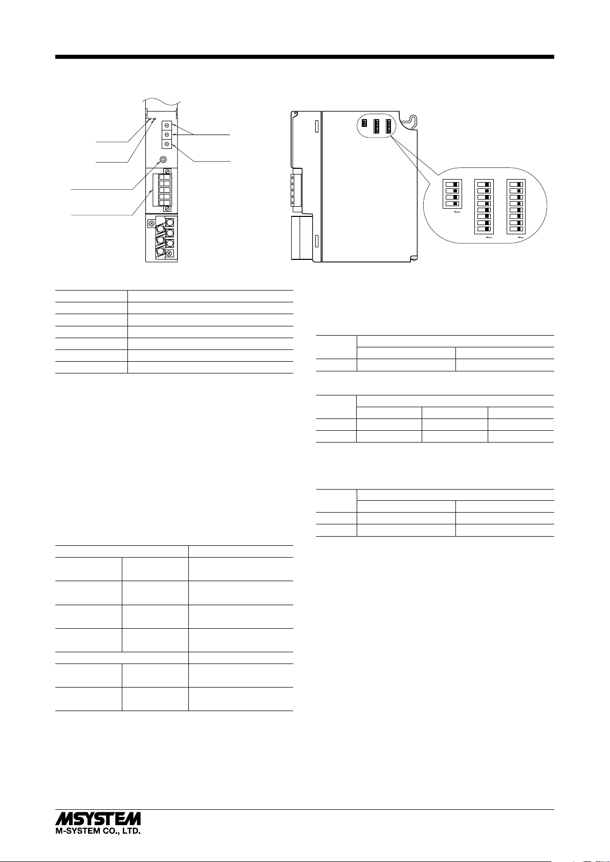
COMPONENT IDENTIFICATION
■ FRONT VIEW ■ SIDE VIEW
8
7
9
Station No.
6
SA1
0
5
1
4
2
3
RUN LED
ERR LED
Configuration Jack
Euro Type
Connector Terminal
SA2
B RATE
x10
x1
4
5
6
Rotary SW
8
7
9
6
0
5
1
4
2
3
8
7
9
6
0
5
1
4
2
3
Baud Rate
Rotary SW
FG
SLD
DG
DB
DA
1
2
3
R3-NC3
DIP SW
SW3
4
3
2
1
ON
SW2
8
7
6
5
4
3
2
1
ON
SW1
8
7
6
5
4
3
2
1
ON
■ BAUD RATE ROTARY SW
SW POSITION BAUD RATE
0 156 kbps
1 625 kbps
2 2.5 Mbps
3 5 Mbps
4 10 Mbps
Other Unused. ERR LED turns on if used.
■ STATION NO. ROTARY SW: SA1, SA2
Station No. is set in decimal.
(Setpoint adjustment: 01 – 64)
■ SIDE DIP SW
(*) Factory setting
• Data Allocation: SW1, SW2
Data Allocation Type* must be assigned to each I/O module
position to specify how many data areas (four types) are to
be occupied by each.
Two bits from SW1 and SW2 are assigned to each position, and data areas can be specified from the module No. 1
through 8. Setting for No. 9 and later modules is identical
to No. 8.
SW ASSIGNMENT MODULE NO.
SW1-1 SW1-2 1
SW1-3 SW1-4 2
SW1-5 SW1-6 3
SW1-7 SW1-8 4
SW2-1 SW2-2 5
SW2-3 SW2-4 6
SW2-5 SW2-6 7
SW2-7 SW2-8 8
SW SETTING DATA ALLOCATION
OFF OFF 1
ON OFF 4
OFF ON 8
ON ON 16
* Refer to the specifications of the related series for the Data
Allocation Type of I/O modules.
• Dual Communication: SW3-1
When two network modules are mounted, one must be
‘Main’ (OFF) network and the other must be ‘Sub’ (ON)
network. For single communication, the network module
must always be set to ‘Main’ (OFF).
SW
DUAL COMMUNICATION
MAIN (*)
SUB
SW3-1 OFF ON
• Cyclic Expansion: SW3-2, 3-3
SW
2 (*)
CYCLIC EXPANSION
4 8
SW3-2 OFF ON OFF
SW3-3 OFF OFF ON
• LED Function: SW3-4
Functions assigned to the front RUN and ERR LEDs can
be selected.
SW3-4
LED FUNCTION
RUN ERR
OFF (*) Green when normal Green when abnormal
ON Red when receiving Red when transmitting
5-2-55, Minamitsumori, Nishinari-ku, Osaka 557-0063 JAPAN
Phone: +81(6)6659-8201 Fax: +81(6)6659-8510 E-mail: info@m-system.co.jp
EM-8422 Rev.12 P. 2 / 7
Page 3
PC CONFIGURATOR
With configurator software, settings shown below are available.
Refer to the software manual of R3CON for detailed operation.
■ NETWORK MODULE SETTING
PARAMETER AVAILABLE RANGE DEFAULT SETTING
Time (no communication time) 0.2 – 3200.0 (sec.) 3.0 (sec.)
TERMINAL CONNECTIONS
Connect the unit as in the diagram below.
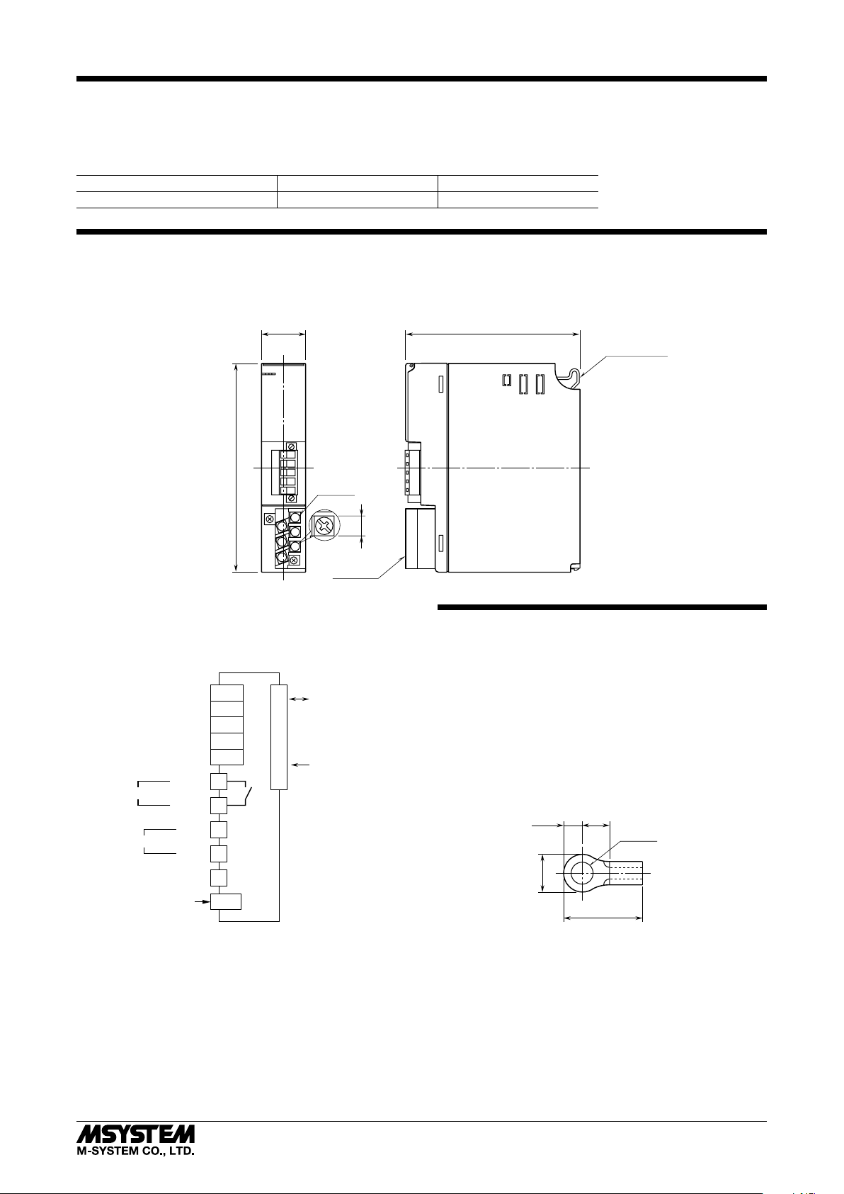
■ EXTERNAL DIMENSIONS unit: mm (inch)
27.5 (1.08)
109 (4.29)
R3-NC3
POSITIONING
GUIDE
6–M3
130 (5.12)
SCREW
1
4
2
5
3
6
6.2
TERMINAL
(.24)
COVER
■ CONNECTION DIAGRAM
Note: In order to improve EMC performance, bond the FG
terminal to ground.
Caution: FG terminal is NOT a protective conductor terminal.
To Other
CC-Link
Devices
RUN CONTACT OUTPUT
*
POWER INPUT
CONFIGURATION JACK
RUN +
RUN –
*Not provided with ‘No Power Supply’ type module.
U (+)
V (–)
*
FG
FG
SLD
DG
DB
DA
1
4
2
3
6
JACK
INTERNAL BUS
INTERNAL POWER
BUS CONNECTOR
WIRING INSTRUCTIONS
■ M3 SCREW TERMINAL (power input, RUN contact output)
Torque: 0.5 N·m
■ SOLDERLESS TERMINAL
Refer to the drawing below for recommended ring tongue
terminal size. Spade tongue type is also applicable. Solderless terminals with insulation sleeve do not fit.
Recommended manufacturer: Japan Solderless Terminal
MFG.Co.Ltd, Nichifu Co.,ltd
Applicable wire size: 0.75 to 1.25 mm
3max
4min
6max
12max
■ EURO TYPE CONNECTOR TERMINAL (CC-Link)
Applicable wire size: 0.2 to 2.5 mm
Stripped length: 7 mm
2
3.2 dia.
(mm)
2
(AWG24 to 12)
5-2-55, Minamitsumori, Nishinari-ku, Osaka 557-0063 JAPAN
Phone: +81(6)6659-8201 Fax: +81(6)6659-8510 E-mail: info@m-system.co.jp
EM-8422 Rev.12 P. 3 / 7
Page 4

COMMUNICATION CABLE CONNECTIONS
■OUTPUT DATA
The figure below shows the allocation of the data sent from
the network module to the master.
■INPUT DATA
The figure below shows the allocation of the data sent from
the master to the network module.
The DIP SW located at the side of the module specifies each I/O module's data allocation (occupied data area).
For example, when the data areas are assigned as shown below:
Module 1 4
Module 2 4
Module 3 4
Module 4 1
Module 5 1
Module 6 1
Module 7 1
Then the I/O data are assigned as in the figures below:
R3-NC3
TERMINATOR
MASTER UNIT
DA
DB
DG
SLD
FG
blue
white
yellow
R3-NC3
DA
DB
DG
SLD
FG
TRANSMISSION DATA DESCRIPTIONS
The DIP SW located at the side of the module specifies each I/O module’s data allocation (occupied data area).
For example, when the data areas are assigned as shown below:
Module 1 4
Module 2 4
Module 3 4
Module 4 1
Module 5 1
Module 6 1
Module 7 1
Then the I/O data are assigned as in the figures below:
■ OUTPUT DATA
The figure below shows the allocation of the data sent from
the network module to the master.
15
RWr n
+0
+2
0
Module 1
+4
+6
Module 2
+8
+10
Module 3
■ INPUT DATA
The figure below shows the allocation of the data sent from
the master to the network module.
15
RWw n
+0
+2
+4
+6
+8
+10
I/O UNIT
DA
DB
DG
SLD
FG
0
Module 1
Module 2
Module 3
+12
+14
+16*m–1
Module 4
Module 5
Module 6
Module 7
+12
+14
+16*m–1
Module 4
Module 5
Module 6
Module 7
[16*m] (m = cyclic expansion setting) data areas are available to the R3-NC3. Total data areas occupied by I/O modules must
be within this limitation.
5-2-55, Minamitsumori, Nishinari-ku, Osaka 557-0063 JAPAN
Phone: +81(6)6659-8201 Fax: +81(6)6659-8510 E-mail: info@m-system.co.jp
EM-8422 Rev.12 P. 4 / 7
Page 5

R3-NC3
0
FEDCBA9 87654321
0
15
RX(n+0)
RX(n+2)
RX(n+m*7–1)
RX(n+1)
Unused
Module Status
Error Status (Burnout Bit)
Data Error Status
Reserved Bit
• Module Status
RX(n+0)0 through RX(n+0)F indicate whether individual I/O module are mounted or not. The bit corresponding to the
mounted slots turns to “1,” and the unmounted slots to “0.”
• Error Status
RX(n+1)0 through RX(n+1)F indicate error status for each module as described below. The bit corresponding to such mod-
ules turns to “1.”
R3-TSx, R3-RSx, R3-US4: Input burnout
R3-DA16A: Power input in error or disconnected
R3-YSx: Output current error (e.g. load unconnected)
• Data Error Status
RX(n+2)0 through RX(n+2)F indicate overrange (R3-US4: out of -10% to +110%; the other types: out of -15% to +115%)
status for each module. The bit corresponding to such modules turns to “1.”
• RX(n+3) through RX(n+m*7–2) are unused.
• RX(n+m*7–1)0 through RX(n+m*7–1)7 are reserved for future use. RX(n+m*7–1)B is assigned to Ready signal, which is
turned to “1” when the network module is in normal conditions. RX(n+m*7–1)8 through RX(n+m*7–1)A, RX(n+m*7–1)C
through RX(n+m*7–1)F are not used.
RX(n+0) 0, RX(n+1) 0, RX(n+2) 0 Module 1
RX(n+0) 1, RX(n+1) 1, RX(n+2) 1 Module 2
RX(n+0) 2, RX(n+1) 2, RX(n+2) 2 Module 3
: :
RX(n+0) F, RX(n+1) F, RX(n+2) F Module 16
MODULE STATUS, ERROR STATUS, DATA ERROR STATUS
Shows each module’s availability and error status.
15
0
Module 1
Module 2
Module 3
:
Module 16
5-2-55, Minamitsumori, Nishinari-ku, Osaka 557-0063 JAPAN
Phone: +81(6)6659-8201 Fax: +81(6)6659-8510 E-mail: info@m-system.co.jp
EM-8422 Rev.12 P. 5 / 7
Page 6

R3-NC3
1 : ON
I/O DATA DESCRIPTIONS
The data allocations for typical I/O modules are shown below.
Refer to the manual for each module for detailed data allocations.
■ OPERATION IN CASE OF A COMMUNICATION ERROR WITH I/O MODULES
When the communication between the network module and the I/O modules is lost due to an error in an input module, the
last process values are held until the communication is re-established.
■ ANALOG DATA (16-bit data, models: R3-SV4, YV4, DS4, YS4 and US4, etc.)
16-bit binary data.
Basically, 0 to 100% of the selected I/O range is converted into 0 to 10000 (binary). Negative percentage is represented in 2’s
complements.
15
0
■ TEMPERATURE DATA (16-bit data, models: R3-RS4, TS4 and US4, etc.)
16-bit binary data.
With °C temperature unit, raw data is multiplied by 10. For example, 25.5°C is converted into 255.
With °F temperature unit, the integer section of raw data is directly converted into the data. For example, 135.4°F is converted into 135.
Minus temperature is converted into negative values, represented in 2’s complements.
15
0
■ ANALOG DATA (16-bit data, models: R3-CT4A, CT4B, etc.)
16-bit binary data.
Integer that engineering unit value (A) multiplied by 100 (for CLSE-R5, integer that engineering unit value (A) multiplied
by 1000).
15
0
■ ACCUMULATED COUNT DATA (32-bit data, models: R3-PA2, PA4A, WT1, WT4, etc.)
32-bit binary data is used for accumulated counts and encoder positions.
Lower 16 bits are allocated from the lowest address to higher ones, higher 16 bits in turn.
15
+0
0
Lower 16 bits
15
+1
0
Higher 16 bits
■ BCD DATA (32-bit data, models: R3-BA32A, BC32A, etc.)
32-bit binary data is used for BCD.
Lower 16 bits are allocated from the lowest address to higher ones, higher 16 bits in turn.
15
+0
15
+1
0
Lower 16 bits
0
Higher 16 bits
■ DISCRETE DATA (models: R3-DA16 and DC16, etc.)
15
0 : OFF
5-2-55, Minamitsumori, Nishinari-ku, Osaka 557-0063 JAPAN
Phone: +81(6)6659-8201 Fax: +81(6)6659-8510 E-mail: info@m-system.co.jp
0
Input 1 (Output 1)
Input 2 (Output 2)
Input 3 (Output 3)
: :
Input 16 (Output 16)
EM-8422 Rev.12 P. 6 / 7
Page 7

R3-NC3
■ PLC REDUNDANT SYSTEM (model: R3-NC3-x/W)
Bit 0 of RY(n+1) is assigned to designate control system or standby system. Set this bit from the host PLC to switch from the
PLC master control system to the standby system, or vice versa. The R3 module output (slave station) is controlled according
to the bit combinations as shown in the table below. No switching is required for the R3 input modules which continuously
send out data to both ‘main’ and ‘sub’ network modules.
RY(n+1) 0 = 0 : PLC master control system
RY(n+1) 0 = 1 : PLC standby system
R3 MAIN (RY(n+1) 0) R3 SUB (RY(n+1) 0) CONTROL
0 0 Output from the ‘main’ network module.
0 1 Output from the ‘main’ network module.
1 0 Output from the ‘sub’ network module.
1 1 Hold the output
• Operation
R3 main network
RY (n+1) 0 = 0
RY (n+1) 0 = 1
Communication Status Start Break Restored Switching by PLC
R3 sub network
RY (n+1) 0 = 0
RY (n+1) 0 = 1
(1) (2) (3) (4) (5)
1) When the PLC master control/standby system bit is undefined due to no communication, the both host PLCs function as
‘standby’ system for each of R3 ‘main’ and ‘sub’ network modules. All contact outputs are off, and analog output modules
output -15%.
2) The master PLC communicates with the R3 main network module, while the standby PLC communicates with the R3 sub
network module.
3) When a wire breakdown is detected at the R3 main network, the output signal is held for the preset time period (Timer is
programmable with the PC Configurator Software, R3CON). After the time has been elapsed, the output is switched from
the R3 main to R3 sub network. Be sure to set an appropriate output signal to the R3 sub network before the switching.
The host PLC for the R3 main network is now functioning as standby system.
4) Once the PLC control is transferred to the standby system, it is necessary to set RY(n+1) 0 = 1 to the R3 main network in
order to prevent R3 output control automatically switched to the main network when the R3 main network is restored. If
it is set to RY(n+1) 0 = 0, the R3 output will be switched to the main network even when the PLC control is in the standby
system.
5) When both R3 main and R3 sub network modules are in communication, the output can be switched without delay by setting RY(n+1) 0 values. Be sure to set an appropriate output signal to the network module before the control is switched to
it.
■ CONNECTION EXAMPLE for R3-NC3-x/W
CPU
Control
MasterMaster
Standby
CPU
MasterMaster
R3-
NC3
Main
R3-
NC3
Sub
I/O
5-2-55, Minamitsumori, Nishinari-ku, Osaka 557-0063 JAPAN
Phone: +81(6)6659-8201 Fax: +81(6)6659-8510 E-mail: info@m-system.co.jp
R3-
NC3
R3-
NC3
I/O
EM-8422 Rev.12 P. 7 / 7
 Loading...