

Page 1
INSTRUCTION MANUAL
DISCRETE OUTPUT MODULE
(NPN transistor output, 16 points)
BEFORE USE ....
Thank you for choosing M-System. Before use, please check
contents of the package you received as outlined below.
If you have any problems or questions with the product,
please contact M-System’s Sales Office or representatives.
■ PACKAGE INCLUDES:
Discrete output module.......................................................(1)
■ MODEL NO.
Confirm Model No. marking on the product to be exactly
what you ordered.
■ INSTRUCTION MANUAL
This manual describes necessary points of caution when
you use this product, including installation, connection and
basic maintenance procedures.
MODEL
R30YN16A
POINTS OF CAUTION
■ CONFORMITY WITH EU DIRECTIVES
•The equipment must be mounted inside the instrument
panel of a metal enclosure.
•The actual installation environments such as panel configurations, connected devices and connected wires may
affect the protection level of this unit when it is integrated in a panel system. The user may have to review the CE
requirements in regard to the whole system and employ
additional protective measures to ensure CE conformity.
■ GENERAL PRECAUTIONS
•Before you remove the terminal block or mount it, turn off
output signals for safety.
■ HOT INSERTION/REMOVAL OF MODULES
•It is possible to replace the module with the power supplied, provided that modules are of the same model number and that the same Installation Base slot is used.
•Turn off output signals before replacing the module for
safety. Note that replacing multiple modules at once may
greatly change line voltage levels. We recommend that
you replace them one by one.
■ ENVIRONMENT
•Indoor use.
•When heavy dust or metal particles are present in the
air, install the unit inside proper housing with sufficient
ventilation.
•Do not install the unit where it is subjected to continuous
vibration. Do not subject the unit to physical impact.
•Environmental temperature must be within -10 to +55°C
(14 to 131°F) with relative humidity within 10 to 90% RH
in order to ensure adequate life span and operation.
■ WIRING
•Do not install cables close to noise sources (relay drive
cable, high frequency line, etc.).
•Do not bind these cables together with those in which
noises are present. Do not install them in the same duct.
•Be sure to attach the terminal cover for safety.
■ AND ....
•The unit is designed to function as soon as power is supplied, however, a warm up for 10 minutes is required for
satisfying complete performance described in the data
sheet.
■ OUTPUT AT THE LOSS OF COMMUNICATION
•Holds the output of the last normally received data.
•“Reset to 0” setting is not available.
5-2-55, Minamitsumori, Nishinari-ku, Osaka 557-0063 JAPAN
Phone: +81(6)6659-8201 Fax: +81(6)6659-8510 E-mail: info@m-system.co.jp
EM-9011 Rev.1 P. 1 / 4
Page 2
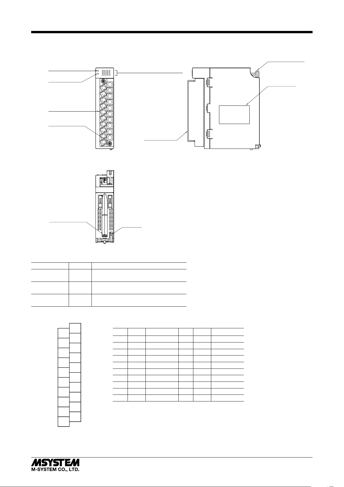
COMPONENT IDENTIFICATION
R30YN16A
■ FRONT VIEW
RUN LED
ERR LED
Output Terminal Block
Terminal Fixing
Screw
■ BOTTOM VIEW
■ SIDE VIEW
Positioning Guide
1
2
3
4
RUN
ERR
Discrete Output Indicator LEDs
5
6
7
8
9
10
11
12
13
14
15
16
1
11
2
12
3
13
4
14
5
15
6
16
7
17
8
18
9
19
10
20
Specifications
Terminal Cover
Base Fixing Screw
Lock Tab
■ STATUS INDICATOR LED
ID
COLOR
FUNCTION
RUN Green ON in normal host communication
OFF in host communication error
ERR Red
OFF when internal bus operates normally
ON when an internal bus error occurs
Discrete Output Green ON when discrete output is ON
OFF when discrete output is OFF
■ TERMINAL ASSIGNMENT
1
Y1
11
12
13
14
15
16
17
18
19
20
Y9
Y10
Y11
Y12
Y13
Y14
Y15
Y16
V+
V–
2
Y2
3
Y3
4
Y4
5
Y5
6
Y6
7
Y7
8
Y8
9
V+
10
V–
NO. ID FUNCTION NO.ID FUNCTION
1Y1
2Y212 Y10
3Y313 Y11
4Y414 Y12
5Y515 Y13
6Y616 Y14
7Y717 Y15
8Y818 Y16
9 24 V DC 19 V +
Output 1
Output 2
Output 3
Output 4
Output 5
Output 6
Output 7
Output 8
V +
10 V –0 V20V –0 V
11 Y9
Output 9
Output 10
Output 11
Output 12
Output 13
Output 14
Output 15
Output 16
24 V DC
5-2-55, Minamitsumori, Nishinari-ku, Osaka 557-0063 JAPAN
Phone: +81(6)6659-8201 Fax: +81(6)6659-8510 E-mail: info@m-system.co.jp
EM-9011 Rev.1 P. 2 / 4
Page 3

INSTALLATION
■ INSTALLATION TO THE BASE
Use the Installation Base (model: R30BS).
The I/O slots are numbered in the ascending order starting
from the one on the immediate right side of the network
module (slot 1, slot 2...).
A code indicating the I/O slot number is assigned to each
I/O slot and I/O data is allocated in the order of this code.
When an I/O slot is vacant, blank data is sent or received to/
from the PLC, etc.
PWR COM I/O1 I/O n
■ HOW TO MOUNT THE MODULE
1) Engage the positioning guide of the module with the Installation Base.
2) Pivot the module on the positioning guide and press it
down until the lock tab sits into place.
R30YN16A
■ HOW TO REMOVE THE MODULE
1) Loosen the base fixing screw using a screwdriver (stem
length: 70 mm/2.76” or more).
Base Fixing Screw
2) While pressing the projection on the lock tab, push the
module upward.
3) Detach the positioning guide of the module from the Installation Base.
Positioning Guide
3) Tighten the base fixing screw using a screwdriver (stem
length: 70 mm/2.76” or more) (torque 0.5 N·m).
Base Fixing Screw
Lock Tab
5-2-55, Minamitsumori, Nishinari-ku, Osaka 557-0063 JAPAN
Phone: +81(6)6659-8201 Fax: +81(6)6659-8510 E-mail: info@m-system.co.jp
EM-9011 Rev.1 P. 3 / 4
Page 4

TERMINAL CONNECTIONS
Connect the unit as in the diagram below.
■ EXTERNAL DIMENSIONS unit: mm (inch)
R30YN16A
■ CONNECTION DIAGRAM
INTERNAL
BUS
INTERNAL
POWER
BUS CONNECTOR
110 (4.33)
1
Y1
2
Y2
3
Y3
4
Y4
5
Y5
6
Y6
7
Y7
8
Y8
11
Y9
12
Y10
13
Y11
14
Y12
15
Y13
16
Y14
17
Y15
18
Y16
9
V+
19
V+
10
V-
20
V-
25 (.98)
⑪
⑫
⑬
⑭
⑮
⑯
⑰
⑱
⑲
⑳
①
②
③
④
⑤
⑥
⑦
⑧
⑨
⑩
20–M3
SCREW
–+
98 (3.86)
6
(.24)
WIRING INSTRUCTIONS
■ TIGHTENING TORQUE
Separable screw terminal wiring screw: 0.5 N·m
Separable screw terminal fixing screw: 0.5 N·m
■ SOLDERLESS TERMINAL unit: mm (inch)
Refer to the drawing below for recommended ring tongue
terminal size. Spade tongue type is also applicable. Solderless terminals with insulation sleeve do not fit.
Applicable wire size: 0.25 to 0.75 mm
Recommended manufacturer: Japan Solderless Terminal
MFG. Co., Ltd., Nichifu Co., Ltd.
3 (.12) max.
(.24)
6 max.
12 (.47) max.
■ HOW TO REMOVE SEPARABLE SCREW TERMINAL
The terminal block is separable in two pieces. Evenly loosen two screws on top and bottom of the terminal block to
separate.
2
3.2 (.13) dia.
■ Output Connection Example
1
Y1
18
Y16
9
V+
19
V+
10
V-
20
V-
–+
5-2-55, Minamitsumori, Nishinari-ku, Osaka 557-0063 JAPAN
Phone: +81(6)6659-8201 Fax: +81(6)6659-8510 E-mail: info@m-system.co.jp
EM-9011 Rev.1 P. 4 / 4
 Loading...