

Page 1

INSTRUCTION MANUAL
EtherCAT INTERFACE I/O MODULE
BEFORE USE ....
Thank you for choosing M-System. Before use, please check
contents of the package you received as outlined below.
If you have any problems or questions with the product,
please contact M-System’s Sales Office or representatives.
■ PACKAGE INCLUDES:
Interface module .................................................................(1)
■ MODEL NO.
Confirm Model No. marking on the product to be exactly
what you ordered.
■ INSTRUCTION MANUAL
This manual describes necessary points of caution when
you use this product, including installation, connection and
basic maintenance procedures.
■ ESI FILE
ESI files are downloadable at M-System’s web site (http://
www.m-system.co.jp).
MODEL
R30GECT1
POINTS OF CAUTION
■ CONFORMITY WITH EU DIRECTIVES
• The equipment must be mounted inside the instrument
panel of a metal enclosure.
• The actual installation environments such as panel configurations, connected devices, connected wires, may affect the protection level of this unit when it is integrated
in a panel system. The user may have to review the CE
requirements in regard to the whole system and employ
additional protective measures to ensure the CE conformity.
■ HOT-SWAPPABLE MODULES
• It is possible to replace a module with the power supplied
provided that the module is replaced with one with the
same model number and installed in the same base slot.
• Turn off signals before replacing the module for safety.
Note that replacing multiple modules at once may greatly
change line voltage levels. We highly recommend to replace them one by one.
■ ENVIRONMENT
• Indoor use.
• When heavy dust or metal particles are present in the
air, install the unit inside proper housing with sufficient
ventilation.
• Do not install the unit where it is subjected to continuous
vibration. Do not subject the unit to physical impact.
• Environmental temperature must be within -10 to +55°C
(14 to 131°F) with relative humidity within 10 to 90% RH
in order to ensure adequate life span and operation.
■ WIRING
• Do not install cables close to noise sources (relay drive
cable, high frequency line, etc.).
• Do not bind these cables together with those in which
noises are present. Do not install them in the same duct.
■ AND ....
• The unit is designed to function as soon as power is supplied, however, a warm up for 10 minutes is required for
satisfying complete performance described in the data
sheet.
• Please use this unit with an interface module (model:
R30NECT1) of firmware version V1.04.10 or higher, and
an interface module (model: R30NCIE1) of firmware version V1.01.13 or higher.
EtherCAT® is a registered trademark and patented technology, licensed by Beckhoff Automation GmbH, Germany.
5-2-55, Minamitsumori, Nishinari-ku, Osaka 557-0063 JAPAN
Phone: +81(6)6659-8201 Fax: +81(6)6659-8510 E-mail: info@m-system.co.jp
EM-9029 P. 1 / 12
Page 2
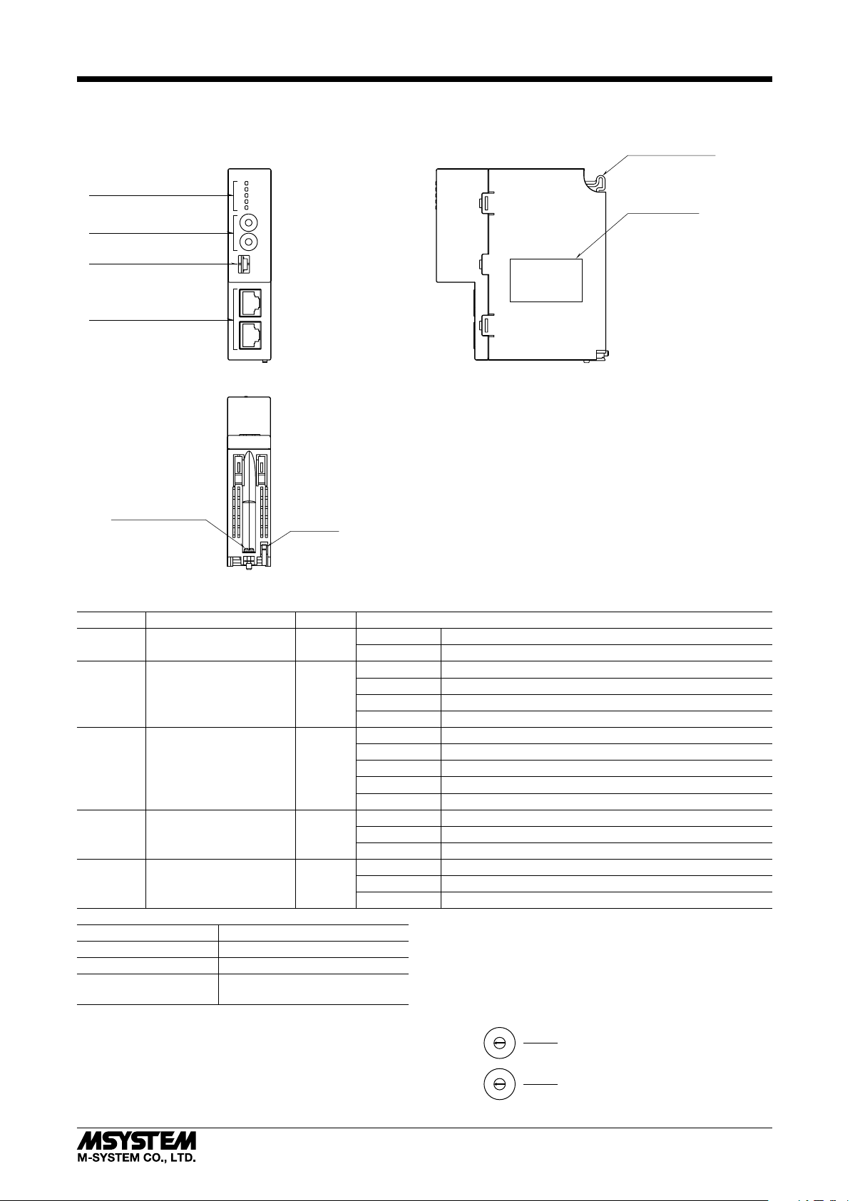
COMPONENT IDENTIFICATION
R30GECT1
■ FRONT VIEW
Status Indicator LEDs
Fixed Address Setting
Rotary SW
Not in use
EtherCAT Communication
RJ-45 Modular Jack
■ BOTTOM VIEW
Base Fixing Screw
L/A
EtherCAT
■ SIDE VIEW
Positioning Guide
PWR
RUN
ERR
OUTINL/A
×
16
Dev ID
×
1
ECT
OUT
ECT
IN
Specifications
Lock Tab
■ STATUS INDICATOR LED
ID FUNCTION
PWR Main unit internal power Green
COLOR
Off Error
On Normal
Off INIT
RUN Device state Green
Blinking PRE-OPERATIONAL
Single Flash SAFE-OPERATIONAL
On OPERATIONAL
Off No error
Blinking Invalid Configuration
ERR Error Red
Single Flash Local error
Double Flash Process data watchdog timeout/EtherCAT watchdog timeout
On Application Controller failure
Off No Link
L/A IN IN port status Green
Flickering Link and activity
On Link without activity
Off No Link
L/A OUT OUT port status Green
Flickering Link and activity
On Link without activity
Blinking 200ms-On, 200ms-Off
Single Flash 200ms-On, 1000ms-Off
Flickering 50ms-On, 50ms-Off
Double Flash 200ms-On, 200ms-Off, 200ms-On,
1000ms-Off
STAT U S
■ FIXED ADDRESS
Fixed address 1 to 255 can be set using the two rotary
switches each marked 0 to F in combination.
When fixed address is not used, set the ID selector to 0.
Settable range: 0 to 255
Factory default: 0
5
4
6
3
7
2
8
1
9
0
A
F
B
E
C
D
5
4
6
3
7
2
8
1
9
0
A
F
B
E
C
D
Fixed Address Setting (x16)
Fixed Address Setting (x1)
5-2-55, Minamitsumori, Nishinari-ku, Osaka 557-0063 JAPAN
Phone: +81(6)6659-8201 Fax: +81(6)6659-8510 E-mail: info@m-system.co.jp
EM-9029 P. 2 / 12
Page 3

INSTALLATION
Positioning Guide
Base Fixing Screw
■ INSTALLATION TO THE BASE
Use the Installation Base (model: R30BS).
The I/O slots are numbered in the ascending order starting
from the one on the immediate right of the interface module
(slot 1, slot 2...).
A code indicating the I/O slot number is assigned to each
I/O slot and I/O data is allocated in the order of the codes.
When an I/O slot is vacant, blank data is sent or received to/
from the PLC, etc.
PWR COM I/O1 I/On
■ HOW TO MOUNT THE MODULE
1) Engage the positioning guide of the module with the Installation Base.
2) Pivot the module on the positioning guide and press it
down until the lock tab clicks into place.
R30GECT1
■ HOW TO REMOVE THE MODULE
1) Loosen the base fixing screw using a screwdriver (stem
length: 70 mm/2.76” or more).
Base Fixing Screw
2) While pressing the projection on the lock tab, push the
module upward.
3) Detach the positioning guide of the module from the Installation Base.
3) Tighten the base fixing screw using a screwdriver (stem
length: 70 mm/2.76” or more) (torque 0.5 N·m).
Lock Tab
5-2-55, Minamitsumori, Nishinari-ku, Osaka 557-0063 JAPAN
Phone: +81(6)6659-8201 Fax: +81(6)6659-8510 E-mail: info@m-system.co.jp
EM-9029 P. 3 / 12
Page 4
TERMINAL CONNECTIONS
Connect the unit as in the diagram below.
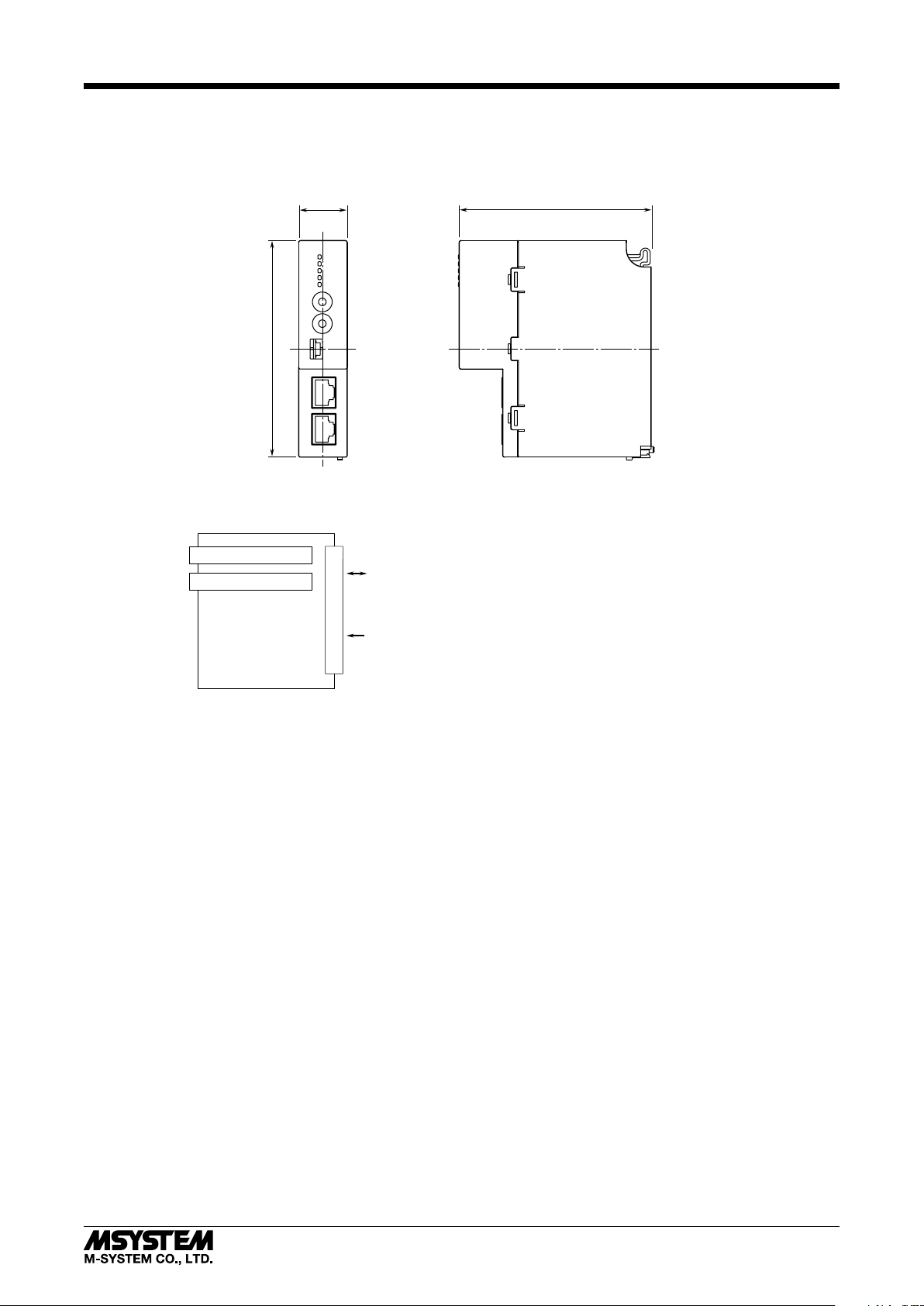
■ EXTERNAL DIMENSIONS unit : mm (inch)
R30GECT1
■ CONNECTION DIAGRAM
EtherCAT (IN)
EtherCAT (OUT)
RJ-45 MODULAR JACK
RJ-45 MODULAR JACK
25 (.98)
110 (4.33)
INTERNAL
BUS
INTERNAL
POWER
CONNECTOR
98 (3.86)
5-2-55, Minamitsumori, Nishinari-ku, Osaka 557-0063 JAPAN
Phone: +81(6)6659-8201 Fax: +81(6)6659-8510 E-mail: info@m-system.co.jp
EM-9029 P. 4 / 12
Page 5

R30GECT1
EtherCAT SPECIFICATIONS
■ Modular Device Prole
R30GECT1 complies with the Modular Device Profile (MDP) standard, ETG.5001.1 of the EtherCAT standard.
Be sure that the master supports the MDP standard.
■ Fixed Address
R30GECT1 supports Explicit Device Identification by allowing setting of fixed address using the fixed address setting rotary
switches (ID selector).
The fixed address can be set to 1 to 255.
When fixed address is not used, set the ID selector to 0.
When the power is turned on with the ID selector set to other than 0, the designated address is written in the register 0x0012
(Configured Station Alias) of ESC (EtherCAT Slave Controller) when R30GECT1 starts up.
■ Process Data Conguration
The number of data R30GECT1 can transmits: 4 points (4 words) for input; and 4 points (4 words) for output.
■ Data Conguration
The data configuration is in accordance with the EtherCAT Modular Device Profile (MDP) specifications.
Table 1: Data Conguration
OBJECT ADDRESS CONTENT
Device Type 0x1000 Device type
Error register 0x1001 Error register
Manufacturer Device Name 0x1008 Device name
Manufacturer Hardware Version 0x1009 Hardware version
Manufacturer Software Version 0x100A Software version
Identity Objects 0x1018 Vendor information
PDO Mapping Objects (RxPDO) 0x1600 Output data list
RxPDO Gap 0x1701 Output data gap
PDO Mapping Objects (TxPDO) 0x1A00 Input data list
PDO Mapping Objects (TxPDO) 0x1AFF Status data list
TxPDO Gap 0x1B01 Input data gap
Sync Manager Type 0x1C00 Sync manager type
PDO Assign (OUT) 0x1C12 Output data transmission order
PDO Assign (IN) 0x1C13 Input data transmission order
Sync Manager Parameter Objects 0x1C32, 0x1C33 Sync manager parameter
Manufacturer Specific Objects 0x2000 Module status
Input Area Objects 0x6000 Input data
Output Area Objects 0x7000 Output data
Information Data Objects 0x9000 Module information
Modular Device Profile Objects 0xF000 MDP information
Configured Module Ident List 0xF030 Module information collation by master module
Detected Module Ident List 0xF050 Module information list
■ EtherCAT State
EtherCAT defines four states of slave: INIT, PREOP, SAFEOP, and OP.
TxPDO (input configuration data) is updated in the SAFEOP or OP state, and RxPDO (output configuration data) is updated
only in the OP state.
The RUN LED turns on only in the OP state and input data and output data are updated, while only input data is updated
in the PREOP state.
5-2-55, Minamitsumori, Nishinari-ku, Osaka 557-0063 JAPAN
Phone: +81(6)6659-8201 Fax: +81(6)6659-8510 E-mail: info@m-system.co.jp
EM-9029 P. 5 / 12
Page 6

R30GECT1
■ EtherCAT Diagnostics
• AL Status Code
When the slave (R30GECT1) fails to receive a request from the master or when there is a problem with the slave during normal communication, an error code is set to registers 0x0134 and 0x0135 (AL Status Code) of ESC.
See Table 2 below for the error codes used on the R30GECT1.
Table 2: Error Codes of AL Status Code
CODE ERROR
0x0000 No error
0x0011 Invalid requested state change
0x0012 Unknown requested state change
0x0013 BOOT state not supported
0x0016 Invalid MailBox configuration (PREOP)
0x0017 Invalid SyncManager configuration
0x001B SyncManager Watchdog
0x001D Invalid Output Configuration
0x001E Invalid Input Configuration
0x001F Invalid Watchdog Configuration
0x0029 FreeRun needs 3 Buffer mode
0x8000 Internal bus error at power on (vendor specific error)
0x8001 Internal bus error during communication (vendor specific error)
• SDO Abort Code
When the master attempts to access the object dictionary via SDO, if the slave (R30GECT1) fails to receive SDO messages for
any reason, the R30GECT1 sends an error code (SDO Abort Code) to the master and denies its access.
See Table 3 below for the error codes that are used.
Table 3: Error Codes of SDO Abort Code
CODE ERROR
0x05030000 Toggle bit not changed
0x05040001 Client/Server command specifier not valid or unknown
0x05040005 Out of memory
0x06010000 Unsupported access to an object
0x06010002 Attempt to write a read-only object
0x06020000 The object does not exist in the object directory
0x06070010 Data type does not match, length of service parameter does not match
0x06090011 Sub-index does not exist
0x08000020 Data cannot be transferred or stored to the application
0x08000022 Data cannot be transferred or stored to the application because of the present device state
5-2-55, Minamitsumori, Nishinari-ku, Osaka 557-0063 JAPAN
Phone: +81(6)6659-8201 Fax: +81(6)6659-8510 E-mail: info@m-system.co.jp
EM-9029 P. 6 / 12
Page 7

OBJECT DICTIONARY (DATA DESCRIPTION)
■ Input Area Objects (Input Data Area: 0x6000)
Input data of I/O modules is allocated to 0x6000.
Sub-Indexes correspond to channel numbers.
■ Output Area Objects (Output Data Area: 0x7000)
Output data of I/O modules is allocated to 0x7000.
Sub-Indexes correspond to channel numbers.
Table 4: Object Conguration For I/O Data By Module Type
MODULE TYPE INDEX
Analog input,
4 points
Analog output,
4 points
0x6000 0 UINT8 8 RO 4 Number of items
0x7000 0 UINT8 8 RO 4 Number of items
SUB-
INDEX
DATA TYPE BIT ACCESS VALUE CONTENT
1 INT16 16 RO -32768 to 32767 First point input data
2 INT16 16 RO -32768 to 32767 Second point input data
3 INT16 16 RO -32768 to 32767 Third point input data
4 INT16 16 RO -32768 to 32767 Fourth point input data
1 INT16 16 RO -32768 to 32767 First point output data
2 INT16 16 RO -32768 to 32767 Second point output data
3 INT16 16 RO -32768 to 32767 Third point output data
4 INT16 16 RO -32768 to 32767 Fourth point output data
R30GECT1
■ Manufacturer Specic Objects (Module Status: 0x2000)
Status information of the module is allocated to 0x2000.
0x0000 is set when the R30GECT1 communicates with the master normally, while 0x000F is set during non-communication
or communication error with the master.
Table 5: Object Conguration for Module Status
INDEX SUB-INDEX DATA TYPE BIT ACCESS VALUE CONTENT
0x2000 0 UINT8 8 RO 1 Number of items
1 UINT16 16 RO 0x000 / 0x000F Module status information
■ PDO Mapping Objects (Data List: 0x1600, 0x1A00, 0x1AFF)
• Objects 0x1600, 0x1A00
Output data list (RxPDO) and Input data list (TxPDO) are allocated to 0x1600 and 0x1A00, respectively.
RxPDO data and TxPDO data contain Object index, Sub-Index and the number of bits to which they refer to.
For input data, objects 0x6000 to 0x6FFF are referred to.
For output data, objects 0x7000 to 0x7FFF are referred to.
Table 6: Object Conguration For Output Data List and Input Data List
INDEX SUB-INDEX DATA TYPE BIT ACCESS VALUE CONTENT
0x1600
(RxPDO)
0x1A00
(TxPDO)
0 UINT8 8 RO 4 Number of items
1 UINT32 32 RO 0xaaaabbcc aaaa: Index
2 UINT32 32 RO
3 UINT32 32 RO
4 UINT32 32 RO
0 UINT8 8 RO 4 Number of items
1 UINT32 32 RO 0xaaaabbcc aaaa: Index
2 UINT32 32 RO
3 UINT32 32 RO
4 UINT32 32 RO
bb: Sub-Index
cc: Number of bits
bb: Sub-Index
cc: Number of bits
• Object 0x1AFF
Module status list (TxPDO) is allocated to 0x1AFF.
Module status list refers to Object 0x2000. See Table 5 below.
Table 7: Conguration For Object 0x1AFF
INDEX SUB-INDEX DATA TYPE BIT ACCESS VALUE CONTENT
0x1AFF 0 UINT8 8 RO 1 Number of items
1 UINT32 32 RO 0x20000110 Reference object
5-2-55, Minamitsumori, Nishinari-ku, Osaka 557-0063 JAPAN
Phone: +81(6)6659-8201 Fax: +81(6)6659-8510 E-mail: info@m-system.co.jp
EM-9029 P. 7 / 12
Page 8

■ RxPDO / TxPDO Gap (0x1701, 0x1B01)
Objects 0x1701 and 0x1B01 are not used.
■ PDO Assign Objects (PDO Allocation List for Output: 0x1C12, Input: 0x1C13)
Allocation lists for RxPDO and TxPDO are allocated to 0x1C12 and 0x1C13, respectively.
0x1C12 and 0x1C13 contain all of RxPDO data and TxPDO data, respectively.
The indexes stored in 0x1C12 and 0x1C13 are placed in the order they are actually transmitted via PDO.
• PDO group
Assignment of the PDO groups is based on the I/O module types as defined by Information Data Objects.
- PDO group 0: Status
- PDO group 1: Analog I/O module
The PDO group data is transmitted in the following order of priority: Group 0 > Group 1.
Table 8: Object Conguration For PDO Allocation List
INDEX SUB-INDEX DATA TYPE BIT ACCESS VALUE CONTENT
0x1C12 0 UINT8 8 RO 2 Number of items
1 UINT16 16 RO 0x1600 Output data
2 UINT16 16 RO 0x1701 RxPDO Gap
0x1C13 0 UINT8 8 RO 3 Number of items
1 UINT16 16 RO 0x1AFF Status data
2 UINT16 16 RO 0x1A00 Input data
3 UINT16 16 RO 0x1B01 TxPDO Gap
R30GECT1
■ Sync Manager Type (0x1C00)
Sync Manager Type is allocated to 0x1C00 based on the EtherCAT specification.
Table 9: Object Conguration For Sync Manager Type
INDEX SUB-INDEX DATA TYPE BIT ACCESS VALUE CONTENT
0x1C00 0 UINT8 8 RO 4 Number of items
1 UINT8 8 RO 1 Mailbox Write
2 UINT8 8 RO 2 Mailbox Read
3 UINT8 8 RO 3 Process Output Data
4 UINT8 8 RO 4 Process Input Data
■ Sync Manager Parameter Objects (0x1C32, 0x1C33)
Objects 0x1C32 and 0x1C33 do not exist as the values of Sync Manager Parameter are fixed on the R30GECT1.
This unit supports only the Free Run mode and does not support Distributed Clock (DC) mode.
5-2-55, Minamitsumori, Nishinari-ku, Osaka 557-0063 JAPAN
Phone: +81(6)6659-8201 Fax: +81(6)6659-8510 E-mail: info@m-system.co.jp
EM-9029 P. 8 / 12
Page 9

R30GECT1
■ Information Data Objects (Module Information: 0x9000)
Module Information (PDO group, Module Ident) is allocated to 0x9000.
Sub-index is 9 or 10.
Table 10: Object Conguration For Module Information
INDEX SUB-INDEX DATA TYPE BIT ACCESS VALUE CONTENT
0x9000 0 UINT8 8 RO 10 Number of items
9 UINT16 16 RO 1 PDO Group
10 UINT32 32 RO 120 Module Ident
Table 11: PDO Group & Module Ident Of Module
I/O TYPE MODULE TYPE PDO GROUP MODULE IDENT MODULE
AIO4 Analog Input, 4 points; Analog Output, 4 points 1 120 –
■ Modular Device Prole Objects (MDP Information: 0xF000)
Modular Device Profile (MDP) information is allocated to 0xF000.
The Index interval, the maximum number of modules, and the PDO group of the slave device are allocated to Sub-Indexes 1,
2 and 5. See Table 12 below.
Sub-Index 3 and Sub-Index 4 respectively indicate the valid/invalid statuses of 0x8000 and 0x9000.
The allocations are as follows:
bit 0 = 0x8000 (0x9000) Sub-Index 1
bit 1 = 0x8000 (0x9000) Sub-Index 2
:
1: Valid, 0: Invalid
Table 12: Object Conguration For Modular Device Prole (MDP)
INDEX SUB-INDEX DATA TYPE BIT ACCESS VALUE CONTENT
0xF000 0 UINT8 8 RO 5 Number of items
1 UINT16 16 RO 0x0010 Index Interval
2 UINT16 16 RO 1 Maximum number of modules
3 UINT32 32 RO 0x00000000 Valid Sub-Index of 0x8nn0
4 UINT32 32 RO 0x00000300 Valid Sub-Index of 0x9nn0
5 UINT16 16 RO 0 PDO group
5-2-55, Minamitsumori, Nishinari-ku, Osaka 557-0063 JAPAN
Phone: +81(6)6659-8201 Fax: +81(6)6659-8510 E-mail: info@m-system.co.jp
EM-9029 P. 9 / 12
Page 10

R30GECT1
■ Detected Module Ident List (Module Information List: 0xF050)
Module information list is allocated to 0xF050.
Each Sub-Index number in the list represents the module address.
0 is set as the Sub-Index number for a non-existing module. See Table 13 below.
■ Congured Module Ident List (Module Information Collation by Master Module: 0xF030)
0xF030 is referred to for confirming the configuration of modules registered on the master module.
Module Indent is written for each module that is existing (recognized by the master) with Sub-Index number as the module
address.
The slave confirms the Module Ident to determine whether writing is correct (successful) or wrong (failed).
When all is correct, objects 0xF030 and 0xF050 show the same configuration.
0xF030 is solely for the confirmation by the master, and thus can be omitted.
Table 13: Object Conguration For Module Information List
INDEX SUB-INDEX DATA TYPE BIT ACCESS VALUE CONTENT
0xF030 0 UINT8 8 RW 1 Number of items
1 UINT32 32 RW 120 Module Ident or 0 (confirmed by master)
0xF050 0 UINT8 8 RO 1 Number of items
1 UINT32 32 RO 120 Module Ident or 0
■ Device Type (0x1000)
The device type is allocated to 0x1000.
The device type is 5001.
Table 14: Object Conguration For Device Type
INDEX DATA TYPE BIT ACCESS VALUE CONTENT
0x1000 UINT32 32 RO 5001 Device type
■ ERROR REGISTER (0x1001)
The object 0x1001 is not used.
■ Manufacturer Device Name (0x1008)
The device name is allocated to 0x1008 in String form.
Table 15: Object 0x1008 Conguration
INDEX DATA TYPE BIT ACCESS VALUE CONTENT
0x1008 STRING 32 RO R30GECT1 Model number
■ Manufacturer Hardware Version (0x1009)
The hardware device version is allocated to 0x1009 in String form.
The version format is ‘n.nn’.
Table 16: Object Conguration For Hardware Version
INDEX DATA TYPE BIT ACCESS VALUE CONTENT
0x1009 STRING 32 RO n.nn Hardware version
■ Manufacturer Software Version (0x100A)
The software version is allocated to 0x100A in String form.
The version format is ‘n.nn’.
Table 17: Object Conguration For Software Version
INDEX DATA TYPE BIT ACCESS VALUE CONTENT
0x100A STRING 32 RO n.nn Software version
5-2-55, Minamitsumori, Nishinari-ku, Osaka 557-0063 JAPAN
Phone: +81(6)6659-8201 Fax: +81(6)6659-8510 E-mail: info@m-system.co.jp
EM-9029 P. 10 / 12
Page 11

R30GECT1
■ Identity Object (Vendor Information: 0x1018)
Vendor Information is allocated to 0x1018.
While the vendor ID and product code are fixed, the revision number is incremented by one at each major version up of the
software.
A unique serial number is allocated to each product.
A serial number consists of 8 digits, starting with two alpha-numeral characters followed by six numeral characters.
The serial number is expressed as 32-bit data divided into 6-bit, 6-bit and 20-bit groups, with the first two characters converted into 6-bit values.
6 BITS 6 BITS 20 BITS
1st digit 2nd digit 3rd to 8th digits (000000 to 999999)
Serial Number Conversion Table
CHARACTER VALUE
0 0
1 1
: :
9 9
A 10
B 11
: :
Z 35
Table 18: Object Conguration For Vendor Information
INDEX SUB-INDEX DATA TYPE BIT ACCESS VALUE CONTENT
0x1018 0 UINT8 8 RO 4 Number of items
1 UINT32 32 RO 0x0000060C Vendor ID
2 UINT32 32 RO 0x52333008 Product code
3 UINT32 32 RO n Revision number
4 UINT32 32 RO 0 to n Serial number
5-2-55, Minamitsumori, Nishinari-ku, Osaka 557-0063 JAPAN
Phone: +81(6)6659-8201 Fax: +81(6)6659-8510 E-mail: info@m-system.co.jp
EM-9029 P. 11 / 12
Page 12

TRANSMISSION DATA DESCRIPTION
• DATA FLOW
Host PC/PLC
R30GECT1
Input
R30PS1
* R30Nx: R30 Newtork module
Output
data
data
R30Nx* R30GECT1
Output data
(Output Area Objects)
EtherCAT master
Input data
(Input Area Objects)
■ FLOW OF OUTPUT DATA
[EtherCAT master]—>[R30GECT1]—>[R30 internal bus]
—>[R30 Network module]—>[Host PC/PLC]
Output data (Output Area Objects) from EtherCAT master
is transmitted as Input data to Host PC/PLC.
■ FLOW OF INPUT DATA
[Host PC/PLC]—>[R30 Network module]—>[R30 internal bus]
—>[R30GECT1]—>[EtherCAT master]
Output data from Host PC/PLC is transmitted as Input data
(Input Area Objects) to EtherCAT master.
5-2-55, Minamitsumori, Nishinari-ku, Osaka 557-0063 JAPAN
Phone: +81(6)6659-8201 Fax: +81(6)6659-8510 E-mail: info@m-system.co.jp
EM-9029 P. 12 / 12
 Loading...