

Page 1

MODEL: R1M-GH
R1M-GH SPECIFICATIONS ES-5657 Rev.11 Page 1/9
Remote I/O R1M Series
THERMOCOUPLE & DC INPUT MODULE
(16 points)
Functions & Features
• 16-point thermocouple or DC inputs
• Easy system expansion via Modbus RTU
40
(1.57)
115
(4.53)
mm (inch)
175 (6.89)
MODEL: R1M-GH2T-[1][2]
ORDERING INFORMATION
• Code number: R1M-GH2T-[1][2]
Specify a code from below for each [1] and [2].
(e.g. R1M-GH2T-M2/Q)
• Specify the specification for option code /Q
(e.g. /SET)
FIELD TERMINAL TYPE
T: M3 screw terminals
[1] POWER INPUT
AC Power
M2: 100 – 240 V AC (Operational voltage range 85 – 264 V,
47 – 66 Hz)
DC Power
R: 24 V DC
(Operational voltage range 24 V ±10 %, ripple 10 %p-p max.)
[2] OPTIONS
blank: none
/Q: With options (specify the specification)
SPECIFICATIONS OF OPTION: Q
EX-FACTORY SETTING
/SET: Preset according to the Ordering Information Sheet
(No. ESU-5657-A)
RELATED PRODUCTS
• Resistor module (model: REM3-250)
• R1X configurator software (model: R1CON)
Downloadable at M-System’s web site.
A dedicated cable is required to connect the module to the
PC. Please refer to the internet software download site or
the users manual for the PC configurator for applicable
cable types.
GENERAL SPECIFICATIONS
Connection
Power input, transmission: Euro type connector terminal
RS-232-C: 9-pin D-sub connector (male)
(Lock screw No. 4-40 UNC)
I/O: M3 screw terminals
Isolation: Input to RS-232-C or RS-485 to power
Node address setting: Rotary switch; 1 – F (15 nodes)
RUN indicator LED: Green light blinks in normal conditions.
COMMUNICATION
Baud rate: 38.4 kbps
Communication: Half-duplex, asynchronous, no procedure
Protocol: Modbus RTU
Refer to Modbus Protocol Reference Guide (EM-5650) for
supported functions.
■ RS-232-C
Standard: Conforms to RS-232-C, EIA
Transmission distance: 10 meters max.
■ RS-485
Standard: Conforms to RS-485, EIA
Transmission distance: 500 meters max.
Transmission media: Shielded twisted-pair cable (CPEV-S
0.9 dia.)
INPUT SPECIFICATIONS
Input: Thermocouple or DC input, 16 points
(Common negative for DC input)
Measuring Range:
±20 V, ±5 V, ±1 V, ±0.8 V, ±0.2 V, ±50 mV, ±10 mV
Input resistance: 300 kΩ
Thermocouple types: PR, K, E, J, T, B, R, S, C, N, U, L, P
Sampling rate: 100 millisec./16 points
• Trigger input: Dry contact; ON detected at ≤1.5 V
Sensing: Approx. 5 V DC @ 1 mA
INSTALLATION
Power consumption
•AC: Approx. 10 VA
•DC: Approx. 7 W
Operating temperature: -5 to +60°C (23 to 140°F)
Operating humidity: 30 to 90 %RH (non-condensing)
Mounting: Surface or DIN rail
Weight: 400 g (0.88 lb)
Page 2
MODEL: R1M-GH
R1M-GH SPECIFICATIONS ES-5657 Rev.11 Page 2/9
PERFORMANCE (% of measuring range)
Cold junction compensation error: ±3°C or ±5.4°F max.
(at 20°C ±10°C or 68°F ±18°F)
Temp. coefficient: ±0.015 %/°C (±0.008 %/°F)
±0.05 %/°C (±0.03 %/°F) for 10 mV range
Accuracy
DC input: ±0.3 %
Thermocouple input: See the table on the end of this
section.
Insulation resistance: ≥ 100 MΩ with 500 V DC
Dielectric strength: 2000 V AC @ 1 minute (input to RS-232C or RS-485 to power to FG)
Thermocouple Accuracy
T/C
USABLE RANGE
ACCURACY
°C °F (%)
(PR) 0 to 1770 32 to 3218 ±0.5*
1
K (CA) -270 to +1370 -454 to +2498 ±0.3
E (CRC) -270 to +1000 -454 to +1832 ±0.7
J (IC) -210 to +1200 -346 to +2192 ±0.7
T (CC) -270 to +400 -454 to +752 ±1.0
B (RH) 100 to 1820 212 to 3308 ±0.7*
2
R -50 to +1760 -58 to +3200 ±0.7*
1
S -50 to +1760 -58 to +3200 ±0.7*
1
C (
WRe 5-26
) 0 to 2320 32 to 4208 ±0.7
N -270 to +1300 -454 to +2372 ±0.5
U -200 to +600 -328 to +1112 ±0.5
L -200 to +900 -328 to +1652 ±0.3
P (
Platinel II
) 0 to 1395 32 to 2543 ±0.5
*1. ≥400°C or ≥752°F
*2. ≥700°C or ≥1292°F
The described accuracy may be partially not satised when
the temperature ranges below 0°C.
STANDARDS & APPROVALS
EU conformity:
EMC Directive
EMI EN 61000-6-4
EMS EN 61000-6-2
Low Voltage Directive
EN 61010-1
Installation Category II
Pollution Degree 2
Input or RS-232-C/RS-485 to power: Reinforced insulation
(300 V)
Input to RS-232-C/RS-485: Basic insulation (300 V)
RoHS Directive
EN 50581
Page 3
MODEL: R1M-GH
R1M-GH SPECIFICATIONS ES-5657 Rev.11 Page 3/9
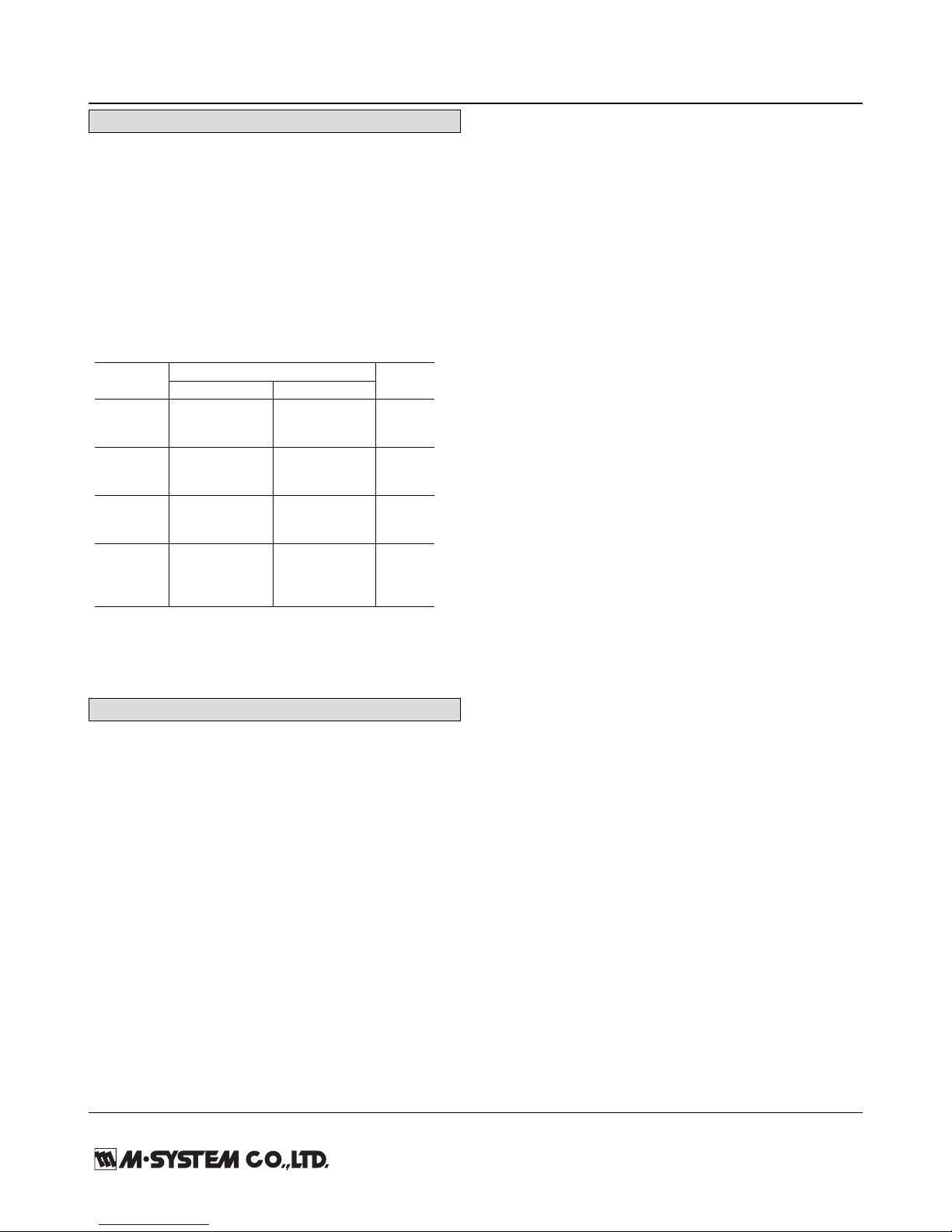
EXTERNAL VIEW
RS-485
Connector
Power Terminals
Node Address
Setting Rotary SW
Configurator
Jack
RUN Indicator
LED
RS-232-C
9-pin Connector
ABBR. PIN NO. EXPLANATION OF FUNCTION
BA (SD) 2 Transmitted Data
BB (RD) 3 Received Data
AB (SG) 5 Signal Common
CB (CS) 7 Clear to Send
CA (RS) 8 Request to Send
1 Not Used.
4 DO NOT connect. Connecting may
6 cause malfunctions.
9
1 5
6 9
■ RS-232-C INTERFACE
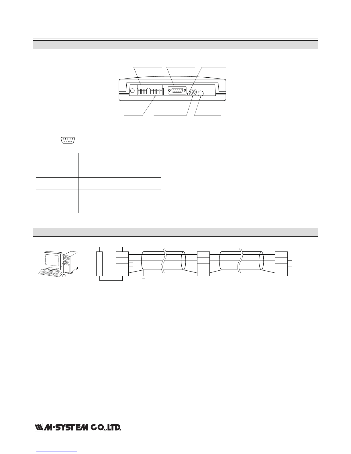
MODBUS WIRING CONNECTION
R1M
T1
T2
T3
T4
R1M
T1
T2
T3
T4
T1
T2
T3
T4
R1M
CONNECTO
R
RS-232-C
RS-485
*
1
*
1
*1. Internal terminating resistor is used when the device is at the end of a transmission line.
*2. Install shielded cables to all sections and ground them at single point.
*
2
FG
RS-485
Page 4

MODEL: R1M-GH
R1M-GH SPECIFICATIONS ES-5657 Rev.11 Page 4/9
CONNECTION DIAGRAM
Note: In order to improve EMC performance, bond the FG terminal to ground.
Caution: FG terminal is NOT a protective conductor terminal.
RS-232-C
T3
T4
T2
T1
T7
T6
T5
Term.
Resist.
Output
Circuit
When the device is located at the end of a transmission line via twisted-pair cable,
(when there is no cross-wiring), close across the terminal T2 –T3 with the attached
jumper pin (or with a leadwire).
When the device is not at the end, remove the jumper pin.
Remark 1: This device is not designed to cancel noise included in the input signals.
Be careful to eliminate such noise by using shielded cables.
Remark 2: Be sure to maintain the same potential at all the common negative
terminals for DC input.
*
9
8
7
6
5
4
3
2
1
10
12
11
13
15
14
16
17
18
20
19
21
22
23
24
25
27
26
28
29
30
31
32
33
35
34
36
TRIGGER INPUT
T/C INPUT
–
+
DC INPUT
INPUT 1
+
–
INPUT 2
INPUT 3
INPUT 4
INPUT 5
INPUT 6
INPUT 7
INPUT 8
INPUT 9
INPUT 10
INPUT 11
INPUT 12
INPUT 13
INPUT 14
INPUT 15
INPUT 16
CJC
Sensor
+
ext. wire
–
+
–
+
–
+
–
+
–
+
–
+
–
+
–
+
–
+
–
+
–
+
–
+
–
+
–
+
–
+
–
+
–
Power
Circuit
Input
Circuit
+
–
Shielded Twisted-pair Cable
To Other
I/O Modules
Jumper*
FG
U (+)
V (–)
POWER
D-SUB CONNECTOR
Page 5

MODEL: R1M-GH
R1M-GH SPECIFICATIONS ES-5657 Rev.11 Page 5/9
MODBUS COMMUNICATION
■ COMMUNICATION PARAMETERS
PARAMETER SPECIFICATION
Data Mode RTU
Baud Rate 9600 / 19200 / 38400 (*) bps
Parity None / Odd (*) / Even
Bit Length 8
Stop Bit 1 (*) / 2
Node Address 1 (*) to 15
Floating Point Data N/A
Interface RS-232-C/ RS-485
(*) Ex-factory setting
■ FUNCTION CODES & SUPPORTED CODES
CODE NAME
01 Read Coil Status X Digital output from the slave
02 Read Input Status X Status of digital inputs to the slave
03 Read Holding Registers X General purpose register within the slave
04 Read Input Registers X Collected data from the field by the slave
05 Force Single Coil X Digital output from the slave
06 Preset Single Registers X General purpose register within the slave
07 Read Exception Status
08 Diagnostics
09 Program 484
10 Poll 484
11 Fetch Comm. Event Counter Fetch a status word and an event counter
12 Fetch Comm. Event Log A status word, an event counter, a message count and a field of event bytes
13 Program Controller
14 Poll Controller
15 Force Multiple Coils X Digital output from the slave
16 Preset Multiple Registers X General purpose register within the slave
17 Report Slave ID Slave type / ‘RUN’ status
18 Program 884/M84
19 Reset Comm. Link
20 Read General Reference
21 Write General Reference
22 Mask Write 4X Register
23 Read/Write 4X Register
24 Read FIFO Queue
Page 6

MODEL: R1M-GH
R1M-GH SPECIFICATIONS ES-5657 Rev.11 Page 6/9
■ DATA ADDRESS
ADDRESS
TYPE
DATA
NAME
GH2 J3 A1 D1
FORMAT
Coil (0X) 1 – 32 --- --- --- Y bit DO *
1
33 – 48 Y --- --- --- bit Cold junction compensation SW
(0: Disable, 1: Enable) *
2
Input Status (1X) 1 – 32 Y Y Y --- bit DI *
3
33 – 48 Y Y --- --- bit ADC overrange
Input Register 1 – 16 Y --- --- --- I AI in % (1 – 8 for Type J3)
(3X) 17 – 48 Y Y --- --- F AI per channel in engineering unit
49 – 50 Y --- --- --- F Cold junction temperature *
2
81 – 96 Y Y --- --- I Channel status
513 Y Y Y Y I Bit System Status
0 to 5 Reserved for system use
6 E
2
PROM diagnostics (0: Normal, 1: Error)
7 ADC error (0: Normal, 1: Error)
8 to 15 Reserved for system use
514 – 521 Y Y Y Y B16 Model No. (“R1M-x”)
522 – 529 Y Y Y Y B16 Serial No.
530 – 537 Y Y Y Y B16 Hardware version No.
538 – 545 Y Y Y Y B16 Firmware version No.
Holding Register 1 – 16 --- --- --- --- I (Reserved for AO in %)
(4X) 17 – 48 --- --- --- --- F (Reserved for AO in engineering unit)
145 – 160 Y Y --- --- I I/O type No.
161 – 176 Y --- --- --- I Burnout type (161 – 168 for Type J3)
(0: No burnout, 1: Upscale, 2: Downscale) *
4
I = 16-bit integer, F = 32-bit floating, B16 = 16-byte character
*1. Discrete output only.
*2. Thermocouple input only.
*3. Trigger contact input for Types GH2 and J3. (Only Address 10001 is enabled.)
*4. Same setting for all channels. For potentiometer inputs, always leave certain residual resistance at 0% side in order to
avoid wrong burnout detection. (0% input or shortcircuit across the terminals 1 – 2 = Wire breakdown at the terminal 3)
Sign
Address n
• 32-bit Floating
Address n+1
Exponent Mantissa
Address n, High-order
• 32-bit Integer, No sign (R1M-A1)
Address n+1, Low order
High order bytesHigh order bytes Low order bytesLow order bytes
■ INPUT DATA
Page 7

MODEL: R1M-GH
R1M-GH SPECIFICATIONS ES-5657 Rev.11 Page 7/9
■ INPUT REGISTERS DESCRIPTION
(1) ANALOG INPUT IN % (30001 to 30016; 30001 to 30008 for J3)
Indicates analog input values in percentage for each channel (1 – 16; 1 – 8 for J3).
(2) ANALOG INPUT IN ENGINEERING UNIT (30017 to 30048; 30017 to 30032 for J3)
Indicates analog input values in engineering unit for each channel (1 – 16; 1 – 8 for J3). The unit is specific to each input type: °C
for temperature, Volts for voltage, and % for potentiometer. The data are 32-bit floating values, which requires two consecutive
registers for one module.
(3) CHANNEL STATUS (30081 to 30096)
Indicates the current status of analog inputs (1 – 16; 1 – 8 for J3). The following list shows the names and descriptions of each bit.
INPUT TYPE & RANGE A/D DATA (Decimal)
DC ±20V ±20000
±5V ±5000
±1V ±10000
±0.8V ±8000
±0.2V ±20000
±50mV ±5000
±10mV ±10000
Thermocouple Temperature x 10
RTD Temperature x 10
Potentiometer 0 – 100Ω ±2000
0 – 500Ω
0 – 1kΩ
0 – 10kΩ
BIT NAME DESCRIPTION
6 Input Overrange Indicates the designated analog input is in overrange, defined as one or
more of the following condition:
• ADC input value 0X0000 or 0XFFFF
• Burnout status for thermocouple input
• Out of range defined in the temperature table (thermocouple and RTD)
• ADC error
0 : Normal
1 : Overrange
7 ADC Error Indicates the status of ADC.
0 : Normal
1 : Error
12 Cold Junction Compensation SW Indicates whether the cold junction compensation is enabled or disabled, for
thermocouple input.
0 : Disable
1 : Enable
Others Reserved For system’s use
Page 8

MODEL: R1M-GH
R1M-GH SPECIFICATIONS ES-5657 Rev.11 Page 8/9
■ INPUT REGISTERS DESCRIPTION
Indicates I/O type for each channel. The data are 16-bit integer values.
MODEL I/O I/O TYPE SELECTION USABLE RANGE NOTES
R1MS-GH3 DC input 0X00 -10 to 10 V -10 to 10 V
R2M-2G3
R1M-GH2 DC input 0X00 -20 to 20 V -22.7 to 22.7 V ATT SW ON
0X01 -5 to 5 V -5.6 to 5.6 V ATT SW ON
0X02 -1 to 1 V -1.4 to 1.4 V ATT SW ON
0X03 -800 to 800 mV -860 to 860 mV
0X04 -200 to 200 mV -215 to 215 mV
0X05 -50 to 50 mV -53 to 53 mV
0X06 -10 to 10 mV -13.4 to 13.4 mV
R1M-GH2 T/C input 0X10 (PR) 0 to 1770 °C
R1MS-GH3 0X11 K (CA) -270 to 1370 °C
R2M-2H3 0X12 E (CRC) -270 to 1000 °C
0X13 J (IC) -210 to 1200 °C
0X14 T (CC) -270 to 400 °C
0X15 B (RH) 100 to 1820 °C
0X16 R -50 to 1760 °C
0X17 S -50 to 1760 °C
0X18 C (WRe 5-26) 0 to 2320 °C
0X19 N -270 to 1300 °C
0X1A U -200 to 600 °C
0X1B L -200 to 900 °C
0X1C P (Platinel II) 0 to 1395 °C
R1M-J3 RTD input 0X30 JPt 100 (JIS ’89) -200 to 500 °C
0X31 Pt 100 (JIS ’89) -200 to 660 °C
0X32 Pt 100 (JIS ’97/IEC) -200 to 850 °C
0X33 Pt 50Ω (JIS ’81) -200 to 649 °C
0X34 Ni 508.4Ω -50 to 280 °C
0X35 Pt 1000 -200 to 850 °C
POT input 0X40 0 to 100 ohms 0 to 100 %
0X41 0 to 500 ohms 0 to 100 %
0X42 0 to 1k ohms 0 to 100 %
0X43 0 to 10k ohms 0 to 100 %
R1M-D1 DO 0X60
R1M-A1 DI 0X70
EXTERNAL DIMENSIONS & TERMINAL ASSIGNMENTS unit: mm (inch)
12345678 9
10 11 12 13 14 15 16 17 18
19 20 21 22 23 24 25 26 27 28 29 30 31 32 33 34 35 35
T1T2 T3 T4
T5T6 T7
104 (4.09)
10 (.39)
105 (4.13)
14 (.55)
163 (6.42)
36–M3 I/O TERMINALS
165 (6.50) 15.5 (.61)
175 (6.89)
FOR WALL MOUNT.
[6 (.24)]
40 (1.57)
3 (.12)
6.2 (.24)
8 (.31)
CJC SENSOR (model: CJM)
3–5 (.20) dia.
MTG HOLES
46 (1.81)
DIN RAIL
35 mm wide
Page 9

MODEL: R1M-GH
R1M-GH SPECIFICATIONS ES-5657 Rev.11 Page 9/9
SYSTEM CONFIGURATION EXAMPLES
RS-485
TC/DC Inputs
(model: R1M-GH)
Contact Inputs
(model: R1M-A1)
Contact Outputs
(model: R1M-D1)
When the cable distance between the PC and the R1Ms is long,
insert an RS-232-C/RS-485 Converter for isolation.
RS-232-C
RS-232-C/RS-485
Converter
(model: R2K-1)
Specifications are subject to change without notice.
 Loading...