

Page 1
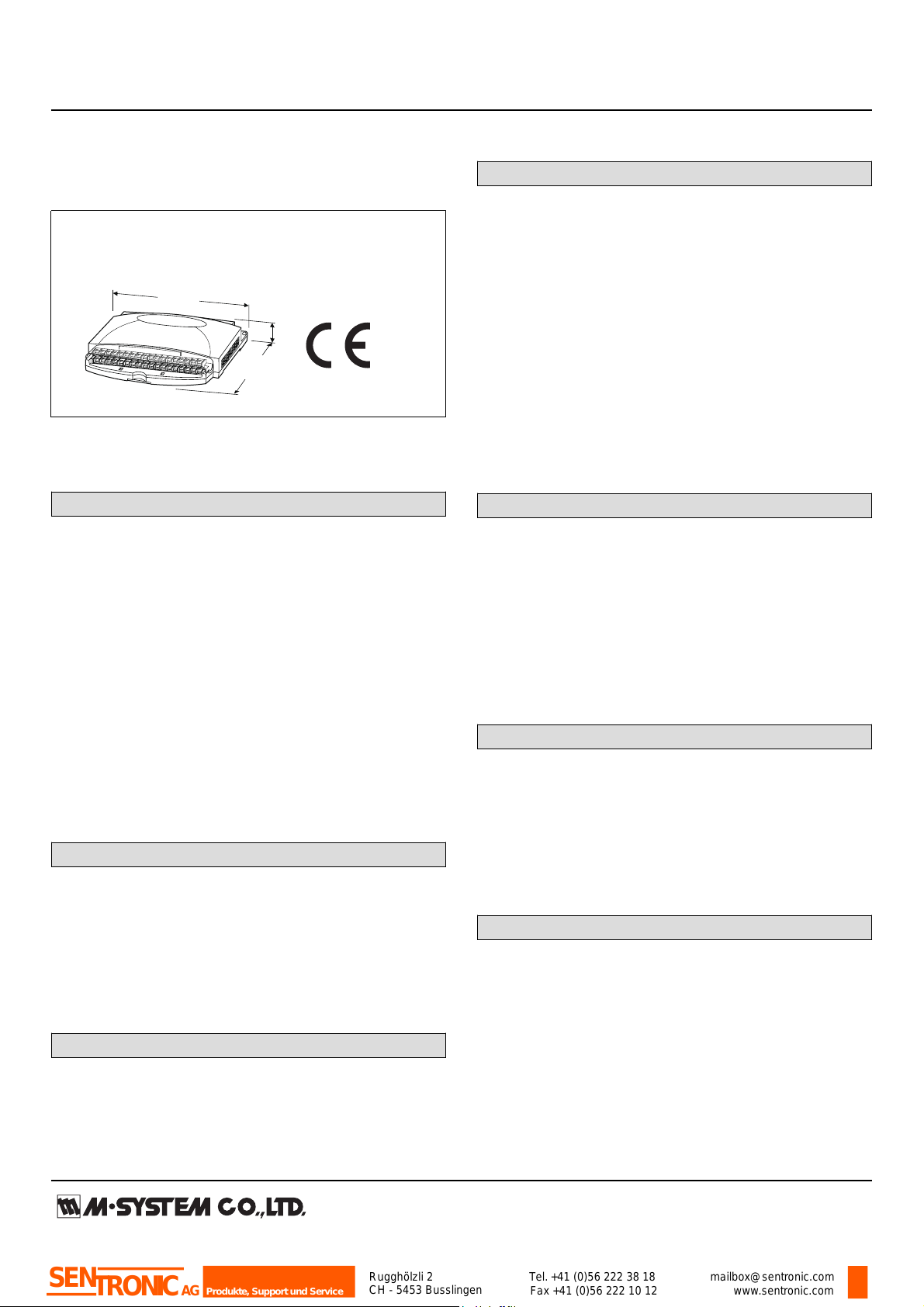
MODEL: R1M-GH
Remote I/O R1M Series
40
(1.57)
115
(4.53)
mm (inch)
175 (6.89)
Rugghölzli 2
CH - 5453 Busslingen
Tel. +41 (0)56 222 38 18
Fax +41 (0)56 222 10 12
mailbox@sentronic.com
www.sentronic.com
Produkte, Support und Service
SEN
TRONIC
AG
RUN indicator LED: Green light blinks in normal conditions.
THERMOCOUPLE & DC INPUT MODULE
(16 points)
Functions & Features
• 16-point thermocouple or DC inputs
• Easy system expansion via Modbus RTU
MODEL: R1M-GH2T-[1]
ORDERING INFORMATION
• Code number: R1M-GH2T-[1]
Specify a code from below for [1]
e.g. R1M-GH2T-M2
FIELD TERMINAL TYPE
T: M3 screw terminals
[1] POWER INPUT
AC Power
M2: 100 – 240 V AC (Operational voltage range 85 – 264 V,
47 – 66 Hz)
DC Power
R: 24 V DC
(Operational voltage range 24 V ±10 %, ripple 10 %p-p max.)
RELATED PRODUCTS
• Resistor module (model: REM3-250)
• R1X configurator software (model: R1CON)
Downloadable at M-System’s web site.
A dedicated cable is required to connect the module to the
PC. Please refer to the internet software download site or
the users manual for the PC configurator for applicable
cable types.
GENERAL SPECIFICATIONS
Connection
Power input, transmission: Euro type connector terminal
RS-232-C: 9-pin D-sub connector (male)
I/O: M3 screw terminals
Isolation: Input to RS-232-C or RS-485 to power
Address setting: Rotary switch; 1 – F (15 nodes)
COMMUNICATION
Baud rate: 38.4 kbps
Communication: Half-duplex, asynchronous, no procedure
Protocol: Modbus RTU
Protocol: Modbus RTU
Refer to Modbus Protocol Reference Guide (EM-5650) for
supported functions.
■ RS-232-C
Standard: Conforms to RS-232-C, EIA
Transmission distance: 10 meters max.
■ RS-485
Standard: Conforms to RS-485, EIA
Transmission distance: 500 meters max.
Transmission media: Shielded twisted-pair cable (CPEV-S
0.9 dia.)
INPUT SPECIFICATIONS
Input: Thermocouple or DC input, 16 points
(Common negative for DC input)
Measuring Range:
±20 V, ±5 V, ±1 V, ±0.8 V, ±0.2 V, ±50 mV, ±10 mV
Input resistance: 300 kΩ
Thermocouple types: PR, K, E, J, T, B, R, S, C, N, U, L, P
Sampling rate: 100 millisec./16 points
• Trigger input: Dry contact; ON detected at ≤1.5 V
Sensing: Approx. 5 V DC @ 1 mA
INSTALLATION
Power Consumption
•AC: Approx. 10 VA
•DC: Approx. 7 W
Operating temperature: -5 to +60°C (23 to 140°F)
Operating humidity: 30 to 90 %RH (non-condensing)
Mounting: Surface or DIN rail
Weight: 400 g (0.88 lbs)
PERFORMANCE (% of measuring range)
Accuracy
DC input: ±0.3 %
Thermocouple input: See the table on the end of this
section.
Cold junction compensation error: ±3°C or ±5.4°F max.
(at 20°C ±10°C or 68°F ±18°F)
Temp. coefficient: ±0.015 %/°C (±0.008 %/°F)
±0.05 %/°C (±0.03 %/°F) for 10 mV range
Insulation resistance: ≥100 MΩ with 500 V DC
Dielectric strength: 2000 V AC @ 1 minute (input to RS-232C or RS-485 to power to ground)
Page 2
MODEL: R1M-GH
Thermocouple Accuracy
T/C
USABLE RANGE
ACCURACY
°C °F (%)
(PR) 0 to 1770 32 to 3218 ±0.5*
1
K (CA) -270 to +1370 -454 to +2498 ±0.3
E (CRC) -270 to +1000 -454 to +1832 ±0.7
J (IC) -210 to +1200 -346 to +2192 ±0.7
T (CC) -270 to +400 -454 to +752 ±1.0
B (RH) 100 to 1820 212 to 3308 ±0.7*
2
R -50 to +1760
-58 to +3200 ±0.7*
1
S -50 to +1760 -58 to +3200
±0.7*
1
C (
WRe 5-26
) 0 to 2320 32 to 4208 ±0.7
N -270 to +1300 -454 to +2372 ±0.5
U -200 to +600 -328 to +1112 ±0.5
L -200 to +900 -328 to +1652 ±0.3
P (
Platinel II
) 0 to 1395 32 to 2543 ±0.5
*1. ≥400°C or ≥752°F
*2. ≥700°C or ≥1292°F
The described accuracy may be partially not satised when
the temperature ranges below 0°C.
STANDARDS & APPROVALS
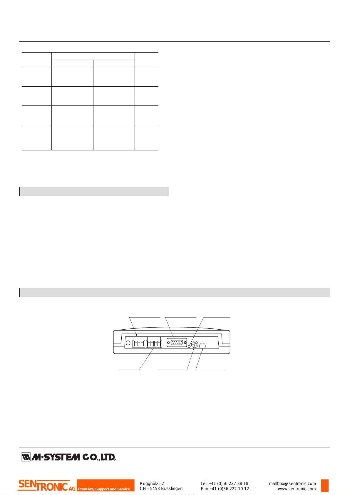
RS-485
Connector
Power Terminals
Address Setting
Rotary SW
Configurator
Jack
RUN Indicator
LED
RS-232-C
9-pin Connector
Rugghölzli 2
CH - 5453 Busslingen
Tel. +41 (0)56 222 38 18
Fax +41 (0)56 222 10 12
mailbox@sentronic.com
www.sentronic.com
Produkte, Support und Service
SEN
TRONIC
AG
CE conformity:
EMC Directive (2004/108/EC)
EMI EN 61000-6-4: 2007
EMS EN 61000-6-2: 2005
Low Voltage Directive (2006/95/EC)
EN 61010-1
Installation Category II
Pollution Degree 2
Input or RS-232-C/RS-485 to power: Reinforced insulation
(300 V)
Input to RS-232-C/RS-485: Basic insulation (300 V)
EXTERNAL VIEW
Page 3
MODEL: R1M-GH
ABBR. PIN NO. EXPLANATION OF FUNCTION
BA (SD) 2 Transmitted Data
BB (RD) 3 Received Data
AB (SG) 5 Signal Common
CB (CS) 7 Clear to Send
CA (RS) 8 Request to Send
1 Not Used.
4 DO NOT connect. Connecting may
6 cause malfunctions.
9
1 5
6 9
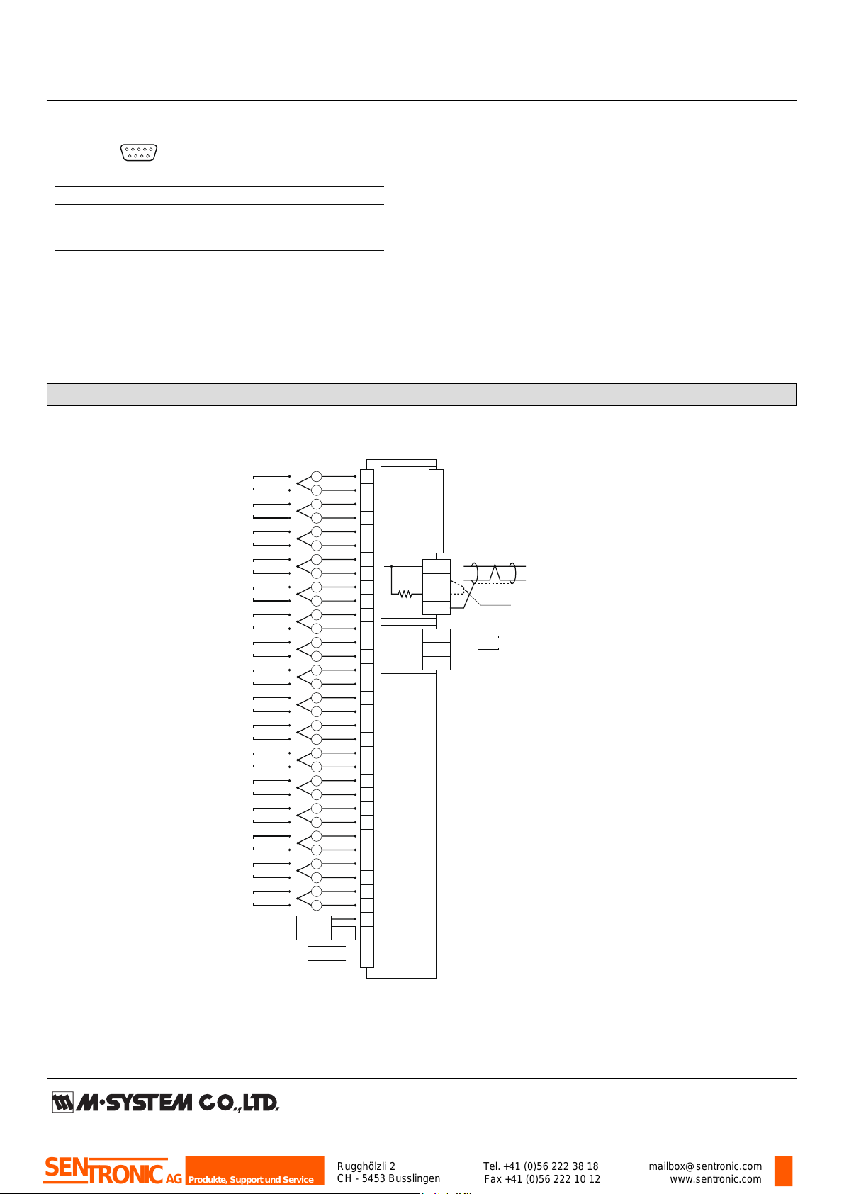
■ RS-232-C INTERFACE
CONNECTION DIAGRAM
RS-232-C
T3
T4
T2
T1
T7
T6
T5
Term.
Resist.
Output
Circuit
When the device is located at the end of a transmission line via twisted-pair cable,
(when there is no cross-wiring), close across the terminal T2 –T3 with the attached
jumper pin (or with a leadwire).
When the device is not at the end, remove the jumper pin.
Remark 1: This device is not designed to cancel noise included in the input signals.
Be careful to eliminate such noise by using shielded cables.
Remark 2: Be sure to maintain the same potential at all the common negative
terminals for DC input.
*
9
8
7
6
5
4
3
2
1
10
12
11
13
15
14
16
17
18
20
19
21
22
23
24
25
27
26
28
29
30
31
32
33
35
34
36
TRIGGER INPUT
T/C INPUT
–
+
DC INPUT
INPUT 1
+
–
INPUT 2
INPUT 3
INPUT 4
INPUT 5
INPUT 6
INPUT 7
INPUT 8
INPUT 9
INPUT 10
INPUT 11
INPUT 12
INPUT 13
INPUT 14
INPUT 15
INPUT 16
CJC
Sensor
+
ext. wire
–
+
–
+
–
+
–
+
–
+
–
+
–
+
–
+
–
+
–
+
–
+
–
+
–
+
–
+
–
+
–
+
–
Power
Circuit
Input
Circuit
+
–
Shielded Twisted-pair Cable
To Other
I/O Modules
Jumper*
FG
U (+)
V (–)
POWER
D-SUB CONNECTOR
Rugghölzli 2
CH - 5453 Busslingen
Tel. +41 (0)56 222 38 18
Fax +41 (0)56 222 10 12
mailbox@sentronic.com
www.sentronic.com
Produkte, Support und Service
SEN
TRONIC
AG
Note: In order to improve EMC performance, bond the FG terminal to ground.
Caution: FG terminal is NOT a protective conductor terminal.
Page 4
MODEL: R1M-GH
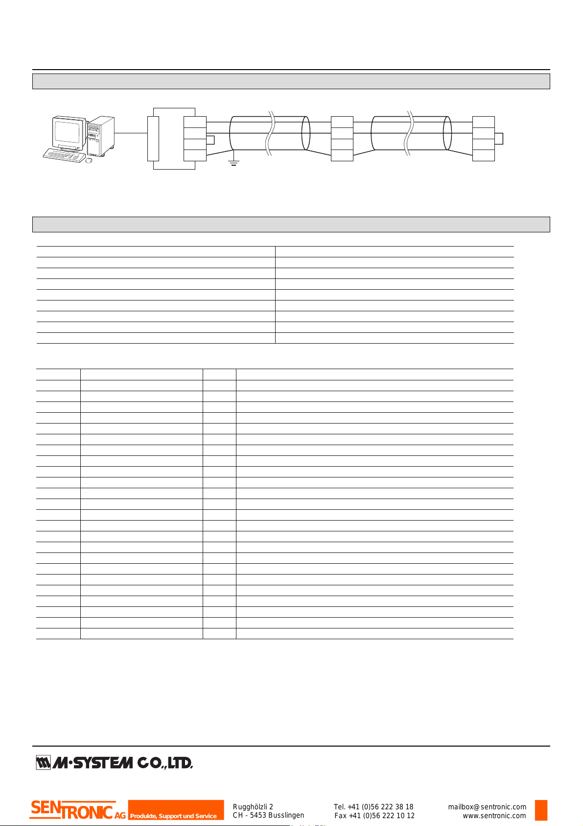
MODBUS WIRING CONNECTION
R1M
T1
T2
T3
T4
R1M
T1
T2
T3
T4
T1
T2
T3
T4
R1M
CONNECTO
R
RS-232-C
RS-485
*
1
*
1
*1. Internal terminating resistor is used when the device is at the end of a transmission line.
*2. Install shielded cables to all sections and ground them at single point.
*
2
FG
RS-485
■ COMMUNICATION PARAMETERS
PARAMETER SPECIFICATION
Data Mode RTU
Baud Rate 9600 / 19200 / 38400 (*) bps
Parity None / Odd (*) / Even
Bit Length 8
Stop Bit 1 (*) / 2
Node Address 1 (*) to 15
Floating Point Data N/A
Interface RS-232-C/ RS-485
(*) Ex-factory setting
■ FUNCTION CODES & SUPPORTED CODES
CODE NAME
01 Read Coil Status X Digital output from the slave
02 Read Input Status X Status of digital inputs to the slave
03 Read Holding Registers X General purpose register within the slave
04 Read Input Registers X Collected data from the field by the slave
05 Force Single Coil X Digital output from the slave
06 Preset Single Registers X General purpose register within the slave
07 Read Exception Status
08 Diagnostics
09 Program 484
10 Poll 484
11 Fetch Comm. Event Counter Fetch a status word and an event counter
12 Fetch Comm. Event Log A status word, an event counter, a message count and a field of event bytes
13 Program Controller
14 Poll Controller
15 Force Multiple Coils X Digital output from the slave
16 Preset Multiple Registers X General purpose register within the slave
17 Report Slave ID Slave type / ‘RUN’ status
18 Program 884/M84
19 Reset Comm. Link
20 Read General Reference
21 Write General Reference
22 Mask Write 4X Register
23 Read/Write 4X Register
24 Read FIFO Queue
Rugghölzli 2
CH - 5453 Busslingen
Tel. +41 (0)56 222 38 18
Fax +41 (0)56 222 10 12
mailbox@sentronic.com
www.sentronic.com
Produkte, Support und Service
SEN
TRONIC
AG
MODBUS COMMUNICATION
Page 5

MODEL: R1M-GH
■ DATA ADDRESS
ADDRESS
TYPE
DATA
NAME
GH2 J3 A1 D1
FORMAT
Coil (0X) 1 – 32 --- --- --- Y bit DO *
1
33 – 48 Y --- --- --- bit Cold junction compensation SW
(0: Disable, 1: Enable) *
2
Input Status (1X) 1 – 32 Y Y Y --- bit DI *
3
33 – 48 Y Y --- --- bit ADC overrange
Input Register 1 – 16 Y --- --- --- I AI in % (1 – 8 for Type J3)
(3X) 17 – 48 Y Y --- --- F AI per channel in engineering unit
49 – 50 Y --- --- --- F Cold junction temperature *
2
81 – 96 Y Y --- --- I Channel status
513 Y Y Y Y I Bit System Status
0 to 5 Reserved for system use
6 E2PROM diagnostics (0: Normal, 1: Error)
7 ADC error (0: Normal, 1: Error)
8 to 15 Reserved for system use
514 – 521 Y Y Y Y B16 Model No. (“R1M-x”)
522 – 529 Y Y Y Y B16 Serial No.
530 – 537 Y Y Y Y B16 Hardware version No.
538 – 545 Y Y Y Y B16 Firmware version No.
Holding Register 1 – 16 --- --- --- --- I (Reserved for AO in %)
(4X) 17 – 48 --- --- --- --- F (Reserved for AO in engineering unit)
145 – 160 Y Y --- --- I I/O type No.
161 – 176 Y --- --- --- I Burnout type (161 – 168 for Type J3)
(0: No burnout, 1: Upscale, 2: Downscale) *
4
I = 16-bit integer, F = 32-bit floating, B16 = 16-byte char
acter
*1. Discrete output only.
*2. Thermocouple input only.
*3. Trigger contact input for Types GH2 and J3. (Only Address 10001 is enabled.)
*4. Same setting for all channels. For potentiometer inputs, always leave certain residual resistance at 0% side in order to
avoid wrong burnout detection. (0% input or shortcircuit across the terminals 1 – 2 = Wire breakdown at the terminal 3)
Sign
Address n
• 32-bit Floating
Address n+1
Exponent Mantissa
Address n, High-order
• 32-bit Integer, No sign
(R1M-A1)
Address n+1, Low order
High order bytesHigh order bytes Low order bytesLow order bytes
■ INPUT DATA
Rugghölzli 2
CH - 5453 Busslingen
Tel. +41 (0)56 222 38 18
Fax +41 (0)56 222 10 12
mailbox@sentronic.com
www.sentronic.com
Produkte, Support und Service
SEN
TRONIC
AG
Page 6

MODEL: R1M-GH
■ INPUT REGISTERS DESCRIPTION
(1) ANALOG INPUT IN % (30001 to 30016; 30001 to 30008 for J3)
Indicates analog input values in percentage for each channel (1 – 16; 1 – 8 for J3).
(2) ANALOG INPUT IN ENGINEERING UNIT (30017 to 30048; 30017 to 30032 for J3)
Indicates analog input values in engineering unit for each channel (1 – 16; 1 – 8 for J3). The unit is specific to each input type: °C
for temperature, Volts for voltage, and % for potentiometer. The data are 32-bit floating values, which requires two consecutive
registers for one module.
(3) CHANNEL STATUS (30081 to 30096)
Indicates the current status of analog inputs (1 – 16; 1 – 8 for J3). The following list shows the names and descriptions of each bit.
INPUT TYPE & RANGE A/D DATA (Decimal)
DC ±20V ±20000
±5V ±5000
±1V ±10000
±0.8V ±8000
±0.2V ±20000
±50mV ±5000
±10mV ±10000
Thermocouple Temperature x 10
RTD Temperature x 10
Potentiometer 0 – 100Ω ±2000
0 – 500Ω
0 – 1kΩ
0 – 10kΩ
BIT NAME DESCRIPTION
6 Input Overrange Indicates the designated analog input is in overrange, defined as one or
more of the following condition:
• ADC input value 0X0000 or 0XFFFF
• Burnout status for thermocouple input
• Out of range defined in the temperature table (thermocouple and RTD)
• ADC error
0 : Normal
1 : Overrange
7 ADC Error Indicates the status of ADC.
0 : Normal
1 : Error
12 Cold Junction Compensation SW Indicates whether the cold junction compensation is enabled or disabled, for
thermocouple input.
0 : Disable
1 : Enable
Others Reserved For system’s use
Rugghölzli 2
CH - 5453 Busslingen
Tel. +41 (0)56 222 38 18
Fax +41 (0)56 222 10 12
mailbox@sentronic.com
www.sentronic.com
Produkte, Support und Service
SEN
TRONIC
AG
Page 7

MODEL: R1M-GH
■ INPUT REGISTERS DESCRIPTION
Indicates I/O type for each channel. The data are 16-bit integer values.
MODEL I/O I/O TYPE SELECTION USABLE RANGE NOTES
R1MS-GH3 DC input 0X00 -10 to 10 V -10 to 10 V
R2M-2G3
R1M-GH2 DC input 0X00 -20 to 20 V -22.7 to 22.7 V ATT SW ON
0X01 -5 to 5 V -5.6 to 5.6 V ATT SW ON
0X02 -1 to 1 V -1.4 to 1.4 V ATT SW ON
0X03 -800 to 800 mV -860 to 860 mV
0X04 -200 to 200 mV -215 to 215 mV
0X05 -50 to 50 mV -53 to 53 mV
0X06 -10 to 10 mV -13.4 to 13.4 mV
R1M-GH2 T/C input 0X10 (PR) 0 to 1770 °C
R1MS-GH3 0X11 K (CA) -270 to 1370 °C
R2M-2H3 0X12 E (CRC) -270 to 1000 °C
0X13 J (IC) -210 to 1200 °C
0X14 T (CC) -270 to 400 °C
0X15 B (RH) 100 to 1820 °C
0X16 R -50 to 1760 °C
0X17 S -50 to 1760 °C
0X18 C (WRe 5-26) 0 to 2320 °C
0X19 N -270 to 1300 °C
0X1A U -200 to 600 °C
0X1B L -200 to 900 °C
0X1C P (Platinel II) 0 to 1395 °C
R1M-J3 RTD input 0X30 JPt 100 (JIS ’89) -200 to 500 °C
0X31 Pt 100 (JIS ’89) -200 to 660 °C
0X32 Pt 100 (JIS ’97/IEC) -200 to 850 °C
0X33 Pt 50Ω (JIS ’81) -200 to 649 °C
0X34 Ni 508.4Ω -50 to 280 °C
0X35 Pt 1000 -200 to 850 °C
POT input 0X40 0 to 100 ohms 0 to 100 %
0X41 0 to 500 ohms 0 to 100 %
0X42 0 to 1k ohms 0 to 100 %
0X43 0 to 10k ohms 0 to 100 %
R1M-D1 DO 0X60
R1M-A1 DI 0X70
12345678 9
10 11 12 13 14 15 16 17 18
19 20 21 22 23 24 25 26 27 28 29 30 31 32 33 34 35 35
T1 T2T3 T4
T5 T6T7
104 (4.09)
10 (.39)
105 (4.13)
14 (.55)
163 (6.42)
36–M3 I/O TERMINALS
165 (6.50) 15.5 (.61)
175 (6.89)
FOR WALL MOUNT.
[6 (.24)]
40 (1.57)
3 (.12)
6.2 (.24)
8 (.31)
CJC SENSOR (model: CJM)
3–5 (.20) dia.
MTG HOLES
46 (1.81)
DIN RAIL
35 mm wide
Rugghölzli 2
CH - 5453 Busslingen
Tel. +41 (0)56 222 38 18
Fax +41 (0)56 222 10 12
mailbox@sentronic.com
www.sentronic.com
Produkte, Support und Service
SEN
TRONIC
AG
EXTERNAL DIMENSIONS & TERMINAL ASSIGNMENTS unit: mm (inch)
Page 8

MODEL: R1M-GH
SYSTEM CONFIGURATION EXAMPLES
RS-485
TC/DC Inputs
(model: R1M-GH)
Contact Inputs
(model: R1M-A1)
Contact Outputs
(model: R1M-D1)
When the cable distance between the PC and the R1Ms is long,
insert an RS-232-C/RS-485 Converter for isolation.
RS-232-C
RS-232-C/RS-485
Converter
(model: R2K-1)
Specifications are subject to change without notice.
Rugghölzli 2
CH - 5453 Busslingen
Tel. +41 (0)56 222 38 18
Fax +41 (0)56 222 10 12
mailbox@sentronic.com
www.sentronic.com
Produkte, Support und Service
SEN
TRONIC
AG
Page 9

INSTRUCTION MANUAL
Rugghölzli 2
CH - 5453 Busslingen
Tel. +41 (0)56 222 38 18
Fax +41 (0)56 222 10 12
mailbox@sentronic.com
www.sentronic.com
Produkte, Support und Service
SEN
TRONIC
AG
R1M-GH
THERMOCOUPLE & DC INPUT MODULE
(16 points)
■ POWER INPUT RATING & OPERATIONAL RANGE
•
BEFORE USE ....
Thank you for choosing M-System. Before use, please check
contents of the package you received as outlined below.
If you have any problems or questions with the product,
please contact M-System’s Sales Office or representatives.
This product is for use in general industrial environments,
therefore may not be suitable for applications which require
higher level of safety (e.g. safety or accident prevention systems) or of reliability (e.g. vehicle control or combustion control systems).
For safety, installation and maintenance of this product
must be conducted by qualified personnel.
■ PACKAGE INCLUDES:
Remote I/O module (body + CJC sensor) ..................... (1)
■ MODEL NO.
Confirm Model No. marking on the product to be exactly
what you ordered.
■ INSTRUCTION MANUAL
This manual describes necessary points of caution when
you use this product, including installation, connection and
basic maintenance procedures.
For detailed information on Modbus supported functions,
refer to Modbus Protocol Reference Guide (EM-5650).
The R1M is programmable using the PC configurator software. For detailed information on the PC configuration,
refer to the R1CON instruction manual. The R1CON PC
Configurator Software is downloadable at M-System’s web
site: http://www.m-system.co.jp.
Locate
confirm its operational range as indicated below:
100 – 240V AC rating: 85 – 264V, 47 – 66 Hz, approx. 10VA
24V DC rating: 24V ±10%, approx. 7W
■ GENERAL PRECAUTIONS
• Before
and input signal for safety.
■ ENVIRONMENT
• Indoor use
•
When heavy dust or metal particles are present in the air,
install the module inside proper housing with sufficient
ventilation.
• Do
not install the module where it is subjected to continuous vibration. Do not apply physical impact to the module.
• Environmental
(23 to 140°F) with relative humidity within 30 to 90% RH
in order to ensure adequate life span and operation.
• Be
sure that the ventilation slits are not covered with ca-
bles, etc.
■ WIRING
• Wrong connection ma
• Do not connect cables to moving parts or pull them tightly.
• Do
not install cables (power supply, input and output)
close to noise sources (relay drive cable, high frequency
line, etc.).
• Do
not bind these cables together with those in which
noises are present. Do not install them in the same duct.
MODEL
the power input rating marked on the product and
you remove the module, turn off the power supply
temperature must be within -5 to +60°C
y damage the module.
R1M-GH
POINTS OF CAUTION
■ CONFORMITY WITH EC DIRECTIVES
• This equipment is suitable for use in a Pollution Degree
2 environment and in Installation Category II, with the
maximum operating voltage 300V.
Basic insulation
and RS-232C/RS-485. Prior to installation, check that the
insulation class of this unit satisfies the system requirements.
• Altitude up to 2000 meters
•
The equipment must be mounted inside a panel.
• Insert noise filters. Okaya Electric Industries Model SUPE1H or equivalent for the power source connected to the
unit, and TDK Model ZCAT3035-1330 or equivalent for
the RS-232C cable are recommended.
equipment must be installed such that appropriate
• The
clearance and creepage distances are maintained to conform to CE requirements.
• The
actual installation environments such as panel configurations, connected devices, connected wires, may affect the protection level of this unit when it is integrated
in a panel system. The user may have to review the CE
requirements in regard to the whole system and employ
additional protective measures to ensure the CE conformity.
is maintained between the signal input
■ AND ....
• The
module is designed to function as soon as power is
supplied, however, a warm up for 10 minutes is required
for satisfying complete performance described in the data
sheet.
P. 1 / 4EM-5657 Rev.7
Page 10
R1M-GH
1 2 3 4 5 6 7 8 9
10 11 12 13 14 15 16 17 18
19 20 21 22 23 24 25 26 27 28 29 30 31 32 33 34 35 35
T1 T2 T3 T4
T5 T6 T7
CJC Sensor (model: CJM)
RS-485
Connector
Address Setting
Rotary SW
Configurator
Jack
Specifications Marking
Power Terminals
RS-232C
9-pin Connector
RUN Indicator
LED
DIN Rail Adaptor
DIN Rail
35mm wide
1 2 3 4 5 6 7 8 9
10 11 12 13 14 15 16 17 18
19 20 21 22 23 24 25 26 27 28 29 30 31 32 33 34 35 35
T1 T2 T3 T4
T5 T6 T7
104 (4.09)
10 (.39)
105 (4.13)
14 (.55)
163 (6.42)
36–M3 I/O TERMINALS
165 (6.50) 15.5 (.61)
175 (6.89)
FOR WALL MOUNT.
[6 (.24)]
40 (1.57)
3 (.12)
6.2 (.24)
8 (.31)
CJC SENSOR (model: CJM)
3–5 (.20) dia.
MTG HOLES
46 (1.81)
DIN RAIL
35 mm wide
Rugghölzli 2
CH - 5453 Busslingen
Tel. +41 (0)56 222 38 18
Fax +41 (0)56 222 10 12
mailbox@sentronic.com
www.sentronic.com
Produkte, Support und Service
SEN
TRONIC
AG
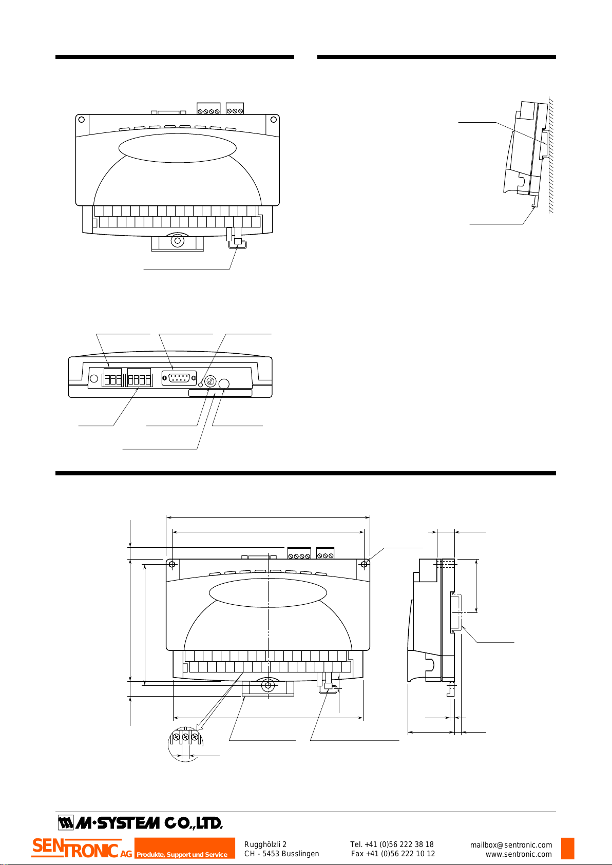
COMPONENT IDENTIFICATION
■ TOP VIEW
■ REAR VIEW
INSTALLATION
■ DIN RAIL MOUNTING
Set the body so that its DIN rail
adaptor is at the bottom. Pull
down the DIN rail adaptor.
Position the upper hook at the
rear side on the DIN rail and
push in the lower. Push back the
DIN rail adaptor.
■ WALL MOUNTING
Set the body so that its DIN rail
adaptor is at the bottom. Pull
down the DIN rail adaptor.
Refer to “EXTERNAL DIMENSIONS.”
EXTERNAL DIMENSIONS unit: mm (inch)
P. 2 / 4EM-5657 Rev.7
Page 11

R1M-GH
R1M
T1
T2
T3
T4
R1M
T1
T2
T3
T4
T1
T2
T3
T4
R1M
CONNECTOR
RS-232C
RS-485
*
1
*
1
*1. Internal terminating resistor is used when the device is at the end of a transmission line.
*2. Install shielded cables to all sections and ground them at single point.
*
2
FG
RS-485
RS-232C
T3
T4
T2
T1
T7
T6
T5
Term.
Resist.
Output
Circuit
When the device is located at the end of a transmission line via twisted-pair cable,
(when there is no cross-wiring), close across the terminal T2 –T3 with the attached
jumper pin (or with a leadwire).
When the device is not at the end, remove the jumper pin.
Remark 1: This device is not designed to cancel noise included in the input signals.
Be careful to eliminate such noise by using shielded cables.
Remark 2: Be sure to maintain the same potential at all the common negative
terminals for DC input.
*
9
8
7
6
5
4
3
2
1
10
12
11
13
15
14
16
17
18
20
19
21
22
23
24
25
27
26
28
29
30
31
32
33
35
34
36
TRIGGER INPUT
T/C INPUT
–
+
DC INPUT
INPUT 1
+
–
INPUT 2
INPUT 3
INPUT 4
INPUT 5
INPUT 6
INPUT 7
INPUT 8
INPUT 9
INPUT 10
INPUT 11
INPUT 12
INPUT 13
INPUT 14
INPUT 15
INPUT 16
CJC
Sensor
+
ext. wire
–
+
–
+
–
+
–
+
–
+
–
+
–
+
–
+
–
+
–
+
–
+
–
+
–
+
–
+
–
+
–
+
–
Power
Circuit
Input
Circuit
+
–
Shielded Twisted-pair Cable
To Other
I/O Modules
Jumper*
FG
U (+)
V (–)
POWER
D-SUB CONNECTOR
1 5
6 9
Rugghölzli 2
CH - 5453 Busslingen
Tel. +41 (0)56 222 38 18
Fax +41 (0)56 222 10 12
mailbox@sentronic.com
www.sentronic.com
Produkte, Support und Service
SEN
TRONIC
AG
TERMINAL CONNECTIONS
Connect the module referring to the connection diagram.
Attach the CJC sensor together with input wiring to the input screw terminals. The sensor is calibrated for each particular
module and not interchangeable with another. Check the serial numbers of the module and sensor.
MODBUS WIRING CONNECTION
■ RS-232C INTERFACE
ABBR. PINNO. EXPLANATIONOFFUNCTION
BA (SD) 2 Transmitted Data
BB (RD) 3 Received Data
AB (SG) 5 Signal Common
CB (CS) 7 Clear to Send
CA (RS) 8 Request to Send
1 Not Used.
4 DO NOT connect. Connecting may
6 cause malfunctions.
9
P. 3 / 4EM-5657 Rev.7
Page 12

INPUT RANGE SELECTING
SW311 SW305 SW304 SW303 SW302
SW405 SW404 SW403 SW402
SW301
O
N
2
1
3
4
5
6
7
8
SW702
SW702 is fixed to
the position 3.
DO NOT CHANGE.
SW411 SW401 SW308 SW307 SW306
SW408 SW407 SW406
O
N
2
1
3
4
5
6
7
8
Rugghölzli 2
CH - 5453 Busslingen
Tel. +41 (0)56 222 38 18
Fax +41 (0)56 222 10 12
mailbox@sentronic.com
www.sentronic.com
Produkte, Support und Service
SEN
TRONIC
AG
Select switches to match the input signal according to the table below.
INPUT SWITCHES SETTING NOTES
Thermocouple
Voltage input, 0.8V or less
Voltage input, above 0.8V (*)
(*) Factory default setting
SW301 – SW308 (ch 1 – ch 8)
SW401 – SW408 (ch 9 – ch 16)
SW311 (ch 1 – ch 8)
SW411 (ch 9 – ch 16)
SW301 – SW308 (ch 1 – ch 8)
SW401 – SW408 (ch 9 – ch 16)
SW311 (ch 1 – ch 8)
SW411 (ch 9 – ch 16)
SW301 – SW308 (ch 1 – ch 8)
SW401 – SW408 (ch 9 – ch 16)
SW311 (ch 1 – ch 8)
SW411 (ch 9 – ch 16)
Set to position “1”
OFF
Set to position “1”
ON
Set to position “3”
ON
Attenuation OFF
Attenuation OFF
Attenuation ON
R1M-GH
CHECKING
1) Terminal wiring: Check that all cables are correctly connected according to the connection diagram.
2) Power input: Chec
k supply voltage.
3) Input: Check that the input is within 0 – 100% of fullscale.
4) DIP SW setting:
Check that all switches are set correct-
ly.
ADJUSTMENT PROCEDURE
This unit is calibrated at the factory to meet the ordered
specifications, therefore you usually do not need any calibration.
M-SYSTEM WARRANTY
M-System
MAINTENANCE
Regular calibration procedure is explained below:
■ CALIBRATION
Warm up the unit for at least 10 minutes. Apply 0%, 25%,
50%, 75% and 100% input signal. Check that the output
signal for the respective input signal remains within accuracy described in the data sheet. When the output is out of
tolerance, please contact M-System’s Sales Office or representatives.
 Loading...