

Page 1

1
PU-2A USERS MANUAL EM-9255-C Rev.14
PROGRAMMING UNIT
FOR JX SERIES TRANSMITTERS
Model: PU-2A
OPERATION MANUAL
8
S
I
5
P
Z
F
2
M
W
C
•
7
R
H
4
O
Y
E
1
L
V
B
0
K
U
A
9
T
J
6
Q
G
3
–
GROUP
ITEM
DATA
#
CLR
UP
DOWN
ENTER
http://www.m-system.co.jp/
5-2-55, Minamitsumori, Nishinari-ku, Osaka 557-0063 JAPAN
Te l: +81-6-6659-8201 Fax: +81-6-6659-8510
E-mail: info@m-system.co.jp
Page 2
2
PU-2A USERS MANUAL EM-9255-C Rev.14
page 5
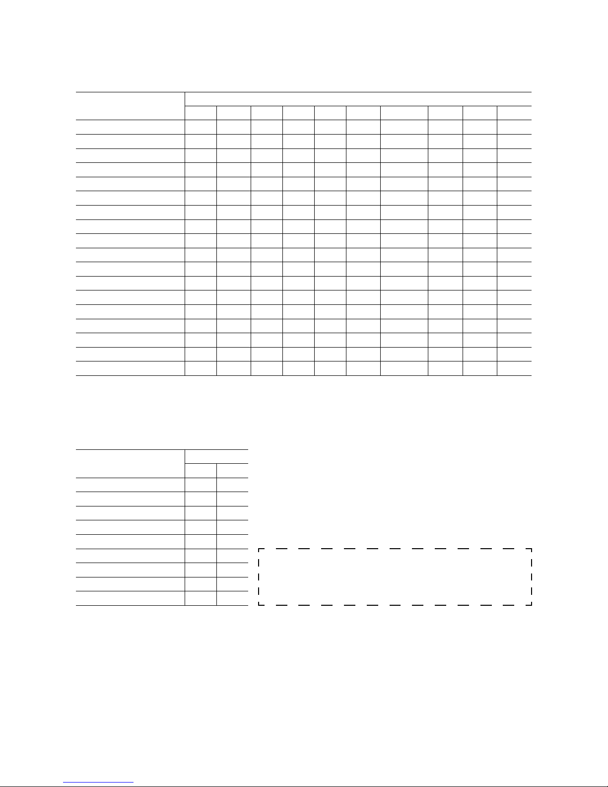
SECTION A. JX Series Field Programmable Signal Conditioners
FUNCTION SERIES
M-UNIT M-RACK F-UNIT H-UNIT H-RACK 10-RACK 18(K)-RACK11-RACK W-UNIT W-RACK
DC INPUT (ISOLATOR) JV 7JV FJV HJV GJV 10JV 18(K)JV 11JV WJV VJV
THERMOCOUPLE JT 7JT FJT HJT GJT 10JT 18(K)JT 11JT WJT VJT
3-wire RTD JR 7JR FJR HJR GJR 10JR 18(K)JR 11JR WJR VJR
4-wire RTD ––– ––– ––– ––– ––– 10JRE ––– ––– ––– –––
POTENTIOMETER JM 7JM FJM HJM GJM 10JM 18(K)JM 11JM WJM VJM
FREQUENCY JPA 7JPA FJPA HJPA GJPA 10JPA 18(K)JPA 11JPA WJPA VJPA
SELF-SYNCH JS 7JS ––– ––– ––– ––– ––– ––– WJS VJS
SQUARE ROOT EXTRACTOR
––– ––– ––– ––– ––– ––– 18JN ––– ––– –––
CURRENT LOOP SUPPLY ––– ––– ––– ––– ––– ––– 18(K)JDN ––– ––– –––
CURRENT LOOP SUPPLY JDL 7JDL FJDL HJDL GJDL 10JDL 18(K)JDL 11JDL ––– –––
LINEARIZER JFX 7JFX FJFX HJFX GJFX 10JFX 18JFX 11JFX WJFX VJFX
100-point LINEARIZER JFX1 ––– ––– ––– ––– ––– ––– ––– ––– –––
2-input MATH JF 7JF FJF HJF GJF 10JF 18JF 11JF WJF VJF
3-input MATH JFK 7JFK ––– ––– ––– ––– ––– 11JFK WJFK VJFK
FILTER/LAG, 8-point JFT 7JFT FJFT HJFT GJFT 10JFT 18JFT 11JFT WJFT VJFT
FILTER/LAG, 100-point JFTS ––– ––– ––– ––– ––– ––– ––– ––– –––
ANALOG BACKUP JB ––– ––– ––– ––– ––– ––– ––– ––– –––
3-input MIDDLE SELECTOR
JFKM ––– ––– ––– ––– ––– ––– ––– ––– –––
page 32
SECTION B. JX Series Field Programmable Pulse Transmitters
FUNCTION
SERIES
M-UNIT W-UNIT
FREQUENCY TO DC JPAD WJPAD
See descriptions on JPAD for WJPAD.
PULSE ACCUMULATOR JPQD
ENCODER SPEED JRPD
ENCODER POSITION JRQD
DC TO 2-PHASE PULSE JARP
DC TO FREQUENCY JAPD
The Model PU-2A is used for those M-System products
other than listed here. Instructions for them are issued
separately for each particular model.
PULSE SCALER JPRD
PULSE ADDER JPSM
FREQUENCY SCALER JFRD
Page 3

3
PU-2A USERS MANUAL EM-9255-C Rev.14
Thank you for choosing M-System. Before starting, please make sure of the following:
PACKAGE INCLUDES:
• Programming Unit ......................................................................................................... 1
• Connection Cable ........................................................................................................... 1
• This Operation Manual ................................................................................................. 1
THIS OPERATION MANUAL CONSISTS OF:
Two sections:
Section A. JX series Field Programmable Signal Conditioners;
Section B. JX series Field Programmable Pulse Transmitters.
PROGRAMMING METHODS FOR EACH SECTION ARE LARGELY DIFFERENT. READ CAREFULLY THE PROPER
SECTION OF THIS MANUAL BEFORE PROGRAMMING.
The Model PU-2A is used for those M-System products other than listed on the cover page of this manual. Instructions
for them are issued separately for each particular model.
■ CAUTIONS !
• Hold the PU-2A securely in your hand when programming.
Never hang the PU-2A unit by the connection cable. Vibration and physical impact by dropping the PU-2A could
cause malfunction of the unit.
• Quick change of ambient temperature and humidity, from low temp. place to high temp. and humidity, could cause
condensation, which may destroy electronic circuitry in the PU-2A.
• Use the PU-2A in ambient temperature: 0 – 45°C.
Page 4

4
PU-2A USERS MANUAL EM-9255-C Rev.14
■ COMPONENT IDENTIFICATION
8
S
I
5
P
Z
F
2
M
W
C
•
7
R
H
4
O
Y
E
1
L
V
B
0
K
U
A
9
T
J
6
Q
G
3
–
GROUP
ITEM
DATA
#
CLR
UP
DOWN
ENTER
DISPLAY
KEYS
SPEC.
LABEL
FRONT VIEW REAR VIEW
TOP VIEW
LCD BRIGHTNESS ADJ.
*MODULAR JACK
PUT A STRAP HERE.
*CONNECTION CABLE IS PROVIDED.
DATA TO BE ENTERED OR MESSAGE
GROUP NO.
# (SHIFT KEY
POSITION)
ITEM NO.
RESPONSE
(ERROR INDICATION)
D
G
I ( )
DISPLAY RESPONSE MESSAGE
OK : O. K.
NG : NO GOOD
NU : NOT USED
ER : ERROR
SHIFT KEY
Used for entering alphabetics. Shift indication changes
as #0, #1, #2, #3, #0 ..... every time the key is pressed.
Level #0 is for entering numbers, and levels #1 to #3 indicate the position of the alphabets from the bottom at
the left of number entry keys.
Page 5

5
PU-2A USERS MANUAL EM-9255-C Rev.14
SECTION A.
JX Series Field Programmable Signal Conditioners
TABLE OF CONTENTS
A-1. INTRODUCTION .................................................................................6
A-2. GENERAL OPERATION DESCRIPTION ...........................................6
DESCRIPTION ............................................................................................................................6
MAINTENANCE SWITCH & OPERATION MODES ....................................................................6
NG MESSAGE .............................................................................................................................7
OUTPUT SIMULATION PROGRAMMING ..................................................................................7
ROM VERSION INDICATION ......................................................................................................7
A-3. GENERAL OPERATION FLOW CHART ............................................8
A-4. INPUT/OUTPUT PROGRAMMING FLOW CHART ............................9
A-5. GROUP 01 TABLE FOR EACH INPUT TYPE...................................10
DC INPUT (ISOLATOR) model xJV ...........................................................................................10
THERMOCOUPLE INPUT model xJT ....................................................................................... 11
3-wire RTD INPUT model xJR ...................................................................................................12
POTENTIOMETER INPUT model xJM ......................................................................................12
4-wire RTD INPUT model 10JRE ..............................................................................................12
FREQUENCY INPUT model xJPA ............................................................................................. 13
SELF-SYNCH INPUT model xJS............................................................................................... 14
SQUARE ROOT EXTRACTOR model 18JN .............................................................................15
sq. root extracting CURRENT LOOP SUPPLY model 18xJDN .................................................. 15
LINEARIZING CURRENT LOOP SUPPLY model xJDL ............................................................ 16
LINEARIZER model xJFX .........................................................................................................17
100-point LINEARIZER model JFX1 .........................................................................................19
2-input MATH FUNCTION model xJF ........................................................................................20
3-input MATH FUNCTION model xJFK .....................................................................................22
FILTER/LAG FUNCTION model xJFT/JFTS .............................................................................25
ANALOG BACKUP STATION model JB ....................................................................................30
3-input MIDDLE SELECTOR model JFKM ................................................................................31
Page 6

6
PU-2A USERS MANUAL EM-9255-C Rev.14
A-1. INTRODUCTION
The fundamental procedures required for conguring input data of the M-System JX series eld programmable signal
conditioners are explained in this section. In order to do this, the Model PU-2A programming unit is required.
Each function is easily programmable via the PU-2A keyboard by selecting a specic number ([DATA] entry for each
[ITEM]) from the table of the specic unit function. The operator need only understand the meaning of each [ITEM]
in order to program the unit. No special programming skills or software is required.
There is specic terminology associated with the PU-2A programming unit. The table categories are called [GROUP],
which define whether the data is common for many types of transmitters or inherent for each transmitter model.
Each group has several [ITEM] numbers, each of which shows what is to be programmed or monitored.
[DATA] is the
specic input value or percentage to be adjusted. The PU-2A programming unit’s operations are based on these three levels:
[GROUP] – [ITEM] – [DATA].
A-2. GENERAL OPERATION DESCRIPTION
■
DESCRIPTION
• When You Want to Monitor the Transmitter Status in Operation:
1) Be sure that the power is supplied to the transmitter.
2) Connect the PU-2A to the transmitter via the front modular jack.
3) Specify an item to be monitored.
Press [GROUP] NN [ITEM] NN. (N = number entry keys)
4) Specify another item if necessary. Repeat (2).
5) Disconnect the PU-2A.
• When You Want to Change Parameters:
1) Be sure that the power is supplied to the transmitter.
2) Connect the PU-2A to the transmitter via the front modular jack.
3) Switch the transmitter into PROGRAM mode with PU-2A.
4) Specify an item to be changed.
Press [GROUP] NN [ITEM] NN [DATA] N (NNN....) [ENTER] (N = number entry keys)
5) Specify another item if necessary. Repeat (3).
6) Disconnect the PU-2A.
■
MAINTENANCE SWITCH & OPERATION MODES
There are two operation modes for JX signal conditioners: MONITOR mode and PROGRAM mode. You use the Maintenance Switch, lock command to prevent unauthorized access to specific data, for changing the operation mode.
In MONITOR mode, the signal conditioner is in normal operation, measuring, computing and outputting signals. You
can only monitor parameter settings, measuring result, output status but cannot affect the transmitter’s operation. No
parameter change except for the Maintenance Switch is available.
In PROGRAM mode, the transmitter stops measuring and renewing the output signal. The output signal is held, but
you can output a specic value for simulation and testing purposes. Parameter settings can be changed.
For changing to the PROGRAM mode, key in [ITEM] 01 [DATA] 1 [ENTER].
The display will appear as shown to the right:
When all the program changes are completed, disconnect the PU-2A. The
Maintenance Switch automatically defaults to “0” (lock position)*.
Do not turn on/off the power supply to the transmitter while the PU-2A is
connected. All memory will be lost if power is removed.
* For those models applicable to Section B, it is necessary to change the Maintenance Switch to MONITOR mode after pro-
gramming. All modication data will be lost if you unplug the PU-2A before returning to MONITOR mode. Read Section B.
DGMIT0S1W:PRG
(.)
MOD
E
Page 7

7
PU-2A USERS MANUAL EM-9255-C Rev.14
■
NG MESSAGE
When there are errors in data entries, the PU-2A display indicates “NG”. Conrm the input data. Do not leave any
items in “NG” status, especially ITEM 10. If ITEM 10 is in “NG” status, all other ITEMs become unavailable. Be sure
to go through checking all ITEMs after ITEM 10 data entry.
■
OUTPUT SIMULATION PROGRAMMING
The output signal of the transmitter is held while in the PROGRAM mode, but you can output a specic value for
simulation and testing purposes. Press [GROUP] 01 [ITEM] 03 [DATA] (desired output value) [ENTER]. The output
value changes in accordance with further adjustments with other [ITEM]s.
• EXAMPLE: 50% output simulated for 1 – 5 V output range.
1 – 5 V range is converted into percentage against 0 – 5 V range with ITEM 3: 20 – 100%.
1) Be sure that the power is supplied to the transmitter.
2) Connect the PU-2A to the transmitter via the front modular jack.
3) Press [GROUP] 01 [DATA] 1 [ENTER].
4) Press [ITEM] 03 [DATA] 50 [ENTER].
5) Specify another group, item and data to cancel the simulated output.
6) Disconnect the PU-2A. (The simulated output is automatically cancelled.)
■
ROM VERSION INDICATION
PROGRAMMING UNIT
When the Programming Unit is connected with a JX transmitter (GROUP and ITEM indications are empty), press [#]
99 and display indicates the ROM version No. of the Programming Unit.
JX TRANSMITTER
Press [GROUP] 00 [ITEM] 99, and display indicates the ROM version No. of the transmitter.
Page 8

8
PU-2A USERS MANUAL EM-9255-C Rev.14
A-3. GENERAL OPERATION FLOW CHART
WARNING!!
DO NOT TURN ON/OFF POWER SUPPLY TO THE TRANSMITTER
WHILE THE PU-2A IS CONNECTED. ALL MEMORY WILL BE LOST
IF POWER IS REMOVED.
The transmitter output signal is held when the PU-2A is connected.
It tracks the input signal only when the input or output monitor
command is entered.
GROUP NO. and ITEM NO. indication is clear.
• [GROUP] 00 : System Table. Clearing the data in the ROM.
Used when erasing segment data for a linearizer module.
• [GROUP] 01 : Used for entering input data for each transmitter.
Each table (GROUP) has a MAINTENANCE SWITCH ([ITEM]
01, lock command) to prevent unauthorized access to specic data.
• [ITEM] 01 [DATA] 0 : The transmitter input and output can be
monitored but cannot be programmed.
(display message = MTSW: MON.MODE)
• [ITEM] 01 [DATA] 1 : The transmitter can now be programmed.
(display message = MTSW: PRG.MODE)
To change the ITEM NO., press [ITEM] and then the number or
press the [UP] or [DOWN] key one or more times.
Press [DATA] and then the number required. When a wrong number is typed, start again with the [DATA] key and input the correct
number.
The display goes back to the data indication state when [CLEAR]
is pressed.
Press [ENTER] to enter the data into the ROM. Programmed data
is again indicated on the display for confirmation.
Then proceed to the next ITEM NO. (Press [ITEM] and then the
number and repeat from Data Indication state.)
The transmitter output starts tracking the input signal.
The MAINTENANCE SWITCH automatically defaults to “0”
(lock position).
DO NOT TURN ON/OFF THE POWER SUPPLY TO THE TRANSMITTER WHILE THE PU-2A IS CONNECTED. ALL MEMORY WILL BE
LOST IF POWER IS REMOVED.
Be sure that power is supplied to the
transmitter.
Connect the PU-2A to the modular jack on
the front of transmitter.
Driving power for the PU-2A is supplied
from the transmitter.
INITIAL STATE
DATA INDICATION
DATA INPUT
ENTER DATA COMMAND
DISCONNECT THE PU-2A
Press [GROUP] [x]
Press [ITEM] [x]
(x: number 0 to 99)
[DATA] [x] ...
[ENTER]
Page 9

9
PU-2A USERS MANUAL EM-9255-C Rev.14
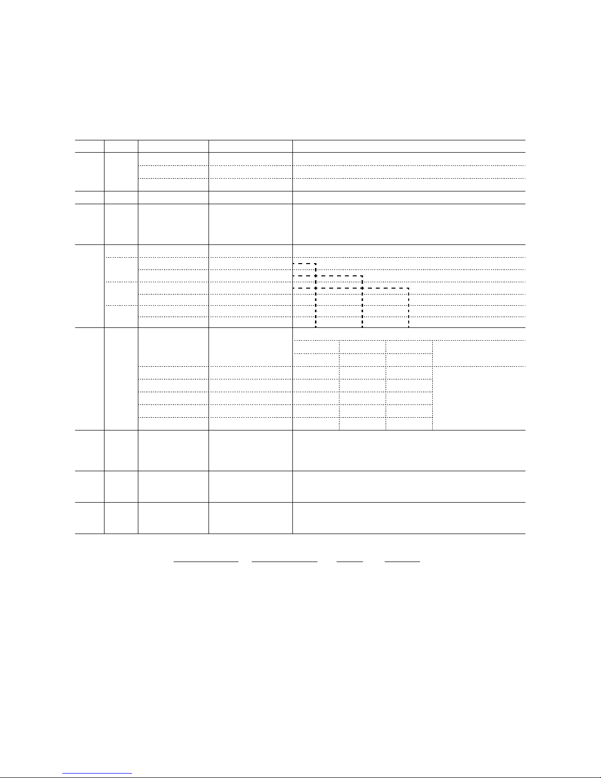
A-4. INPUT/OUTPUT PROGRAMMING FLOW CHART
The JX transmitters process data using an internal digital operation circuit.
The following chart shows a typical input data programming procedure which covers Data Indication, Data Input to
Enter Data Command has been explained on the previous page.
Type in the thermocouple type, RTD type or potenti-
ometer value.
For DC input units, rst type [ITEM] 10 which species the type of transmitter and then type [ITEM] 11
which is used to set the coarse range.
THESE ARE FACTORY SETTING ITEMS ONLY. They
cannot be adjusted by the operator.
Zero and fullscale value adj. (ne adj.) Type in the
actual values for 0% and 100% input.
Used for the JX Linearizer units only.
[GROUP] 01 for Models xJM, 10JRE, xJPA, xJS, xJDL
and xJFX, and [GROUP] 02 & 03 for Model JFX1.
Type in a percentage value for the ZERO and SPAN
adjustments.
THESE ARE FACTORY SETTING ITEMS ONLY. They
cannot be adjusted by the operator.
ITEM 10 - 11 INPUT RANGE ADJUSTMENT
ITEM 12 - 13 INPUT ZERO/SPAN ADJUSTMENTS
ITEM 14 - 15 SCALING
ITEM 60 - 91 LINEARIZATION DATA INPUT
ITEM 19 - 20 FINE ZERO/SPAN ADJUSTMENTS
ITEM 16 - 17 OUTPUT ZERO/SPAN ADJUSTMENTS
Refer to Section A-5 for the specic DATA NO.
for each input type.
See Section A-5. GROUP 01 TABLE.
See Section A-5. LINEARIZATION DATA
TABLE.
Page 10
10
PU-2A USERS MANUAL EM-9255-C Rev.14
A-5. GROUP 01 TABLE FOR EACH INPUT TYPE
In the tables, each MDFY. (modication) mark indicates:
D: No modication (writing) possible. Used only for monitoring (reading).
S: Modiable at any time.
P: Modiable only when the MAINTENANCE SWITCH is in the “PRG” mode.
■
DC INPUT (ISOLATOR) model xJV (Group 01)
ITEM MDFY. DATA INPUT DISPLAY CONTENTS
01 S MAINTENANCE SWITCH (lock command)
0 MTSW: MON.MODE MONITOR mode: data monitoring only
1 MTSW: PRG.MODE PROGRAM mode: “P” marked data modiable
02 P Alphabets & No. TG: XXXXXXXXXX Tag name entry (10 characters max.)
03
05
06
P
D
D
Number (%)
No input
No input
OUTPER XXX.XX
INPPER XXX.XX
INPVAL XXX.XX
Output status monitor (%) & simulation output
Input status monitor (%) *
1
Input status monitor in actual value, same unit as selected in
ITEM 10.
10 TYPE OF TRANSMITTER INPUT *
2
D
11 mV-1: 5 – 100mV
D
12 mV-2: 0.05 – 1V
P
13 mV-3: 0.5 – 10V
P
14 mV-6: 1 – 5V
D
15 mV-A: 4 – 20mA
D
16 mV-H: 10 – 50mA
11 P COARSE INPUT RANGE SELECTION
mV-1 mV-2 mV-3 mV-6/A/H
(± mV) (± V) (± V)
0 INPRNG: XXXX 5 0.05 0.5
1 INPRNG: XXXX 10 0.10 1.0 No
2 INPRNG: XXXX 20 0.20 2.0 Adjustment
3 INPRNG: XXXX 50 0.50 5.0 Needed
4 INPRNG: XXXX 100 1.00 10.0
14
15
PPActual value
Actual value
SCLLOW XXXXXX
SCLHIG XXXXXX
Input range scaling 0% value
Input range scaling 100% value
Use the same engineering unit as the coarse range selected in
ITEM 11.
19 P Percentage FINZER Fine zero adjustment
Initial status shows actual bias (%). When data is entered, output (%)
is shown.
20 P Percentage FINSPN Fine span adjustment
Initial status shows actual gain (%). When data is entered, output
(%) is shown.
REMARK 1 : Percentage of the coarse input range selected in ITEM 11.
(Example)
SCALED RANGE COARSE RANGE INPUT DISPLAY
1 – 5 V 0 – 5 V 1 V 20%
0 – 10 V 0 – 10 V 0 V 0%
-5 – +5 V -5 – +5 V 0 V 0%
-5 – +5 V -5 – +5 V -5 V -100%
REMARK 2 :
Data 13 and 14 are selectable without needing to make hardware change. In order to get 4 – 20 mA or 10 – 50 mA
input, attach a precision resistor to input terminals.
Page 11

11
PU-2A USERS MANUAL EM-9255-C Rev.14
■
THERMOCOUPLE INPUT model xJT (Group 01)
ITEM MDFY. DATA INPUT DISPLAY CONTENTS
01 S MAINTENANCE SWITCH (lock command)
0 MTSW: MON.MODE MONITOR mode: data monitoring only
1 MTSW: PRG.MODE PROGRAM mode: “P” marked data modiable
02 P Alphabets & No. TG: XXXXXXXXXX Tag name entry (10 characters max.)
03
04
PDNumber (%)
No input
OUTPER XXX.XX
OUTTMP XXXX.XX
Output status monitor (%) & simulation output
Output temperature monitor *
1
05
06
07
D
D
D
No input
No input
No input
INPPER XXX.XX
INPVAL XXXXXX
CJMTMP XXX.XX
Input status monitor (%) *
2
Input status monitor in mV
Cold junction compensation temperature (°C)
10 P TYPE OF THERMOCOUPLE
1
Tc-1:
(PR)
(PR)
2
Tc-2: K
(CA)
K (CA)
3
Tc-3: E
(CRC)
E (CRC)
4
Tc-4: J
(IC)
J (IC)
5
Tc-5: T
(CC)
T (CC)
6
Tc-6: B
(RH)
B (RH)
7 Tc-7: R R
8 Tc-8: S S
9 Tc-9: WRe 5-26 WRe 5-26
0 Tc-0: N N
14
15
PPActual value
Actual value
SCLLOW XXXXXX
SCLHIG XXXXXX
Input range scaling 0% value
Input range scaling 100% value
Use the same temp. unit as selected in ITEM 21.
19 P Percentage FINZER Fine zero adjustment
Initial status shows actual bias (%). When data is entered, output
(%) is shown.
20 P Percentage FINSPN Fine span adjustment
Initial status shows actual gain (%). When data is entered, output
(%) is shown.
21 P TEMPERATURE SCALE
0
1
2
TMPSCL: [°C]
TMPSCL: [°F]
TMPSCL: [K]
Program ITEM 21 rst before ITEM 14/15 when °F or K calibra-
tion is needed. This procedure is necessary whenever thermocouple type is changed.
REMARK 1 :
Temperature is indicated in the unit selected in ITEM 21.
REMARK 2 : Percentage of the input range without zero scaling (0 to upper-range value).
(Example)
SCALED RANGE COARSE RANGE INPUT DISPLAY
100 – 1000°C 0 – 1000°C 200°C 20%
Page 12

12
PU-2A USERS MANUAL EM-9255-C Rev.14
■
3-wire RTD INPUT model xJR (Group 01)
ITEM MDFY. DATA INPUT DISPLAY CONTENTS
01 S MAINTENANCE SWITCH (lock command)
0 MTSW: MON.MODE MONITOR mode: data monitoring only
1 MTSW: PRG.MODE PROGRAM mode: “P” marked data modiable
02 P Alphabets & No. TG: XXXXXXXXXX Tag name entry (10 characters max.)
03
04
PDNumber (%)
No input
OUTPER XXX.XX
OUTTMP XXXXXX
Output status monitor (%) & simulation output
Output temperature monitor *
1
06 D No input INPVAL XXXXXX Input status monitor in Ω.
10 TYPE OF RTD
PP31
32
RB-1: Pt 100
RB-2: JPt 100
Pt 100 (JIS ’89)
JPt 100 (JIS ’89)
DD33
34
RB-3: Pt 50
RB-4: Ni 508.4
Pt 50 Ω (JIS ’81)
Ni 508.4 Ω
P 36 RB-6: Pt 100_97 Pt 100 (JIS ’97, IEC)
14
15
PPActual value
Actual value
SCLLOW XXXXXX
SCLHIG XXXXXX
Input range scaling 0% value
Input range scaling 100% value
Use the same temp. unit as selected in ITEM 21.
19 P Percentage FINZER Fine zero adjustment
Initial status shows actual bias (%). When data is entered, output
(%) is shown.
20 P Percentage FINSPN Fine span adjustment
Initial status shows actual gain (%). When data is entered, output
(%) is shown.
21 P TEMPERATURE SCALE
0
1
2
TMPSCL: [°C]
TMPSCL: [°F]
TMPSCL: [K]
Program ITEM 21 rst before ITEM 14/15 when °F or K calibration is needed. This procedure is necessary whenever RTD type is
changed.
REMARK 1 : Temperature is indicated in the unit selected in ITEM 21.
REMARK 2 : Percentage of the input range without zero scaling (0 to upper-range value). See model xJT.
■
POTENTIOMETER INPUT model xJM (Group 01)
4-wire RTD INPUT model 10JRE (Group 01)
ITEM MDFY. DATA INPUT DISPLAY CONTENTS
01 S MAINTENANCE SWITCH (lock command)
0 MTSW: MON.MODE MONITOR mode: data monitoring only
1 MTSW: PRG.MODE PROGRAM mode: “P” marked data modiable
02 P Alphabets & No. TG: XXXXXXXXXX Tag name entry (10 characters max.)
03
05
PDNumber (%)
No input
OUTPER XXX.XX
INPPER XXX.XX
Output status monitor (%) & simulation output
Input status monitor (%) *
1
10 P LINEARIZATION
41 Pm-1: straight Without
42 Pm-2: curved With (ITEM 60 to 91 for data input) *
2
19 P Percentage FINZER Fine zero adjustment
Initial status shows actual bias (%). When data is entered, output
(%) is shown.
20 P Percentage FINSPN Fine span adjustment
Initial status shows actual gain (%). When data is entered, output
(%) is shown.
REMARK 1 : Percentage of the total resistance
REMARK 2 : See LINEARIZER model xJFX table for detailed explanation on curve data programming (ITEM 60 to 91). You
can also specify output percentage for unused resistance range by the linearization table.
Page 13

13
PU-2A USERS MANUAL EM-9255-C Rev.14
■
FREQUENCY INPUT model xJPA (Group 01)
ITEM MDFY. DATA INPUT DISPLAY CONTENTS
01 S MAINTENANCE SWITCH (lock command)
0 MTSW: MON.MODE MONITOR mode: data monitoring only
1 MTSW: PRG.MODE PROGRAM mode: “P” marked data modiable
02 P Alphabets & No. TG: XXXXXXXXXX Tag name entry (10 characters max.)
03
05
06
P
D
D
Number (%)
No input
No input
OUTPER XXX.XX
INPPER XXX.XX
INPFRQ XXXXXX
Output status monitor (%) & simulation output
Input status monitor (%) *
1
Input frequency monitor, same unit as selected in ITEM 11
10 P LINEARIZATION
1 PA-1: straight Without
2 PA-2: curved With (ITEM 60 to 91 for data input) *
2
11 P COARSE FREQUENCY RANGE SELECTION
0
1
2
FRQRNG: 10mHz
FRQRNG: 100mHz
FRQRNG: 1.0Hz
0 – 10 mHz
0 – 100 mHz
0 – 1 Hz
3
4
5
FRQRNG: 10Hz
FRQRNG: 100Hz
FRQRNG: 1.0kHz
0 – 10 Hz
0 – 100 Hz
0 – 1 kHz
6
7
FRQRNG: 10kHz
FRQRNG: 100kHz
0 – 10 kHz
0 – 100 kHz
13 P Percentage DRPOUT XXX.XX Low-end cutout adjustment, 0.00 – 100.00%
14
15
PPActual value
Actual value
SCLLOW XXXXXX
SCLHIG XXXXXX
Input range scaling 0% value
Input range scaling 100% value
Up to 150% of the coarse range selected in ITEM 11. Use the same
unit.
18 P Number SMPLRATE XXX Sampling rate modication for irregular pulse input (No. of pulses
to be counted during one rotation of input owmeter)
Frequency range ≤ 100 Hz: 1 – 255
Frequency range 0 – 1 kHz: 1 – 25
Frequency range 0 – 10 kHz: 1 – 2
19 P Percentage FINZER
Fine zero adjustment
Initial status shows actual bias (%). When data is entered, output
(%) is shown.
20 P Percentage FINSPN
Fine span adjustment
Initial status shows actual gain (%). When data is entered, output
(%) is shown.
REMARK 1 :
Percentage of the coarse input range selected in ITEM 11.
(Example) SCALED RANGE COARSE RANGE INPUT DISPLAY
10 – 100 Hz 0 – 100 Hz 10 Hz 10%
REMARK 2 :
See LINEARIZER model xJFX table for detailed explanation on curve data programming (ITEM 60 to 91).
Page 14

14
PU-2A USERS MANUAL EM-9255-C Rev.14
■
SELF-SYNCH INPUT model xJS (Group 01)
ITEM MDFY. DATA INPUT DISPLAY CONTENTS
01 S MAINTENANCE SWITCH (lock command)
0 MTSW: MON.MODE MONITOR mode: data monitoring only
1 MTSW: PRG.MODE PROGRAM mode: “P” marked data modiable
02 P Alphabets & No. TG: XXXXXXXXXX Tag name entry (10 characters max.)
03
04
05
P
D
D
Number (%)
No input
No input
OUTPER XXX.XX
OUTANG XXX.XX
INPANG XXX.XX
Output status monitor (%) & simulation output
Output angle monitor (degree)
Input angle monitor (degree)
06
07
08
D
D
D
No input
No input
No input
XVALUE XXX.XX
YVALUE XXX.XX
INPOFS XXX.XX
X-axis monitor (voltage: V)
Y-axis monitor (voltage: V)
Input offset setting monitor (degree)
10 P LINEARIZATION
1 SR-1: straight Without
2 SR-2: curved With (ITEM 60 to 91 for data input) *
1
14
15
PPActual value
Actual value
ANGOFS XXX.X
ANGRNG XXX.X
Input offset angle (0%, degrees) *
2
Input range scaling (100%, degrees) *
2
19 P Percentage FINZER Fine zero adjustment
Initial status shows actual bias (%). When data is entered, output
(%) is shown.
20 P Percentage FINSPN Fine span adjustment
Initial status shows actual gain (%). When data is entered, output
(%) is shown.
REMARK 1 :
See LINEARIZER model xJFX table for detailed explanation on curve data programming (ITEM 60 to 91).
REMARK 2 :
After setting ITEM 14 or 15, it is required to perform offset adjustment for the xJS unit, which can be conducted
with the multi-turn screwdriver adjustment over the modular jack of the unit.
TYPICAL SET-UP PROCEDURE
CALIBRATION EXAMPLE
0% input = 60 degrees 0% output = 0 mA
100% input = 300 degrees 100% output = 1 mA
PROCEDURE
1) Apply an input signal which corresponds to 60 degrees.
2) Adjust the potentiometer on the xJS unit (located above the modular phone
jack) until the output reading is exactly 0 mA DC (0%).
3) Apply an input signal which corresponds to 240 degrees.
4) Adjust [ITEM] 20 (FINSPN) until the output reading is exactly 1 mA DC
(100%).
5) Apply 0% input and check that the output is exactly 0 mA DC. If yes, then the unit is calibrated properly.
6) If not, then adjust [ITEM] 19 until the output is exactly 0 mA DC.
7) Repeat steps 3) – 6) until there is no change in 0% and 100% readings.
270°
300°
0°
90°
60°
Page 15

15
PU-2A USERS MANUAL EM-9255-C Rev.14
■
SQUARE ROOT EXTRACTOR model 18JN (Group 01)
sq. root extracting CURRENT LOOP SUPPLY model 18xJDN(Group 01)
ITEM MDFY. DATA INPUT DISPLAY CONTENTS
01 S MAINTENANCE SWITCH (lock command)
0 MTSW: MON.MODE MONITOR mode: data monitoring only
1 MTSW: PRG.MODE PROGRAM mode: “P” marked data modiable
02 P Alphabets & No. TG: XXXXXXXXXX Tag name entry (10 characters max.)
03
05
PDNumber (%)
No input
OUTPER XXX.XX
INPPER XXX.XX
Output status monitor (%) & simulation output
Input status monitor (%)
10 P 41
42
Sq-1: Nodrop
Sq-2: Dropout
Square root output, without low-end cutout
Square root output, with low-end cutout
19 P Percentage FINZER Fine zero adjustment
Initial status shows actual bias (%). When data is entered, output
(%) is shown.
20 P Percentage FINSPN Fine span adjustment
Initial status shows actual gain (%). When data is entered, output
(%) is shown.
Page 16

16
PU-2A USERS MANUAL EM-9255-C Rev.14
■
LINEARIZING CURRENT LOOP SUPPLY model xJDL (Group 01)
ITEM MDFY. DATA INPUT DISPLAY CONTENTS
01 S MAINTENANCE SWITCH (lock command)
0 MTSW: MON.MODE MONITOR mode: data monitoring only
1 MTSW: PRG.MODE PROGRAM mode: “P” marked data modiable
02 P Alphabets & No. TG: XXXXXXXXXX Tag name entry (10 characters max.)
03
04
PDNumber (%)
No input
OUTPER XXX.XX
OUTTMP XXXX.XX
Output status monitor (%) & simulation output
Output temperature monitor *
1
05
06
DDNo input
No input
INPPER XXX.XX
INPVAL XXXXXX
Input status monitor (%) *
2
Input status monitor in mV
10 P TYPE OF LINEARIZATION
1
Tc-1:
(PR)
Thermocouple (PR)
2
Tc-2: K
(CA)
K (CA)
3
Tc-3: E
(CRC)
E (CRC)
4
Tc-4: J
(IC)
J (IC)
5
Tc-5: T
(CC)
T (CC)
6
Tc-6: B
(RH)
B (RH)
7 Tc-7: R R
8 Tc-8: S S
9 Tc-9: WRe 5-26 WRe 5-26
11 PS: Straight Proportional output
21 FX: Linearizer Segment data linearization *
3
31 RB-1: Pt 100 RTD Pt 100 (JIS ’97, IEC, JIS ’89)
32 RB-2: JPt 100 JPt 100 (JIS ’89)
33 RB-3: Pt 50 Pt 50 Ω (JIS ’81)
34 RB-4: Ni 508.4 Ni 508.4 Ω
41 Sq-1: Nodrop Square root output, without low-end cutout
42 Sq-2: Dropout Square root output, with low-end cutout
14
15
PPActual value
Actual value
SCLLOW XXXXXX
SCLHIG XXXXXX
Temperature range scaling 0% value *
1
Temperature range scaling 100% value *
1
19 P Percentage FINZER Fine zero adjustment
Initial status shows actual bias (%). When data is entered, output
(%) is shown.
20 P Percentage FINSPN Fine span adjustment
Initial status shows actual gain (%). When data is entered, output
(%) is shown.
21 P TEMPERATURE SCALE
0
1
2
TMPSCL: [°C]
TMPSCL: [°F]
TMPSCL: [K]
Program ITEM 21 rst before ITEM 14/15 when °F or K calibration
is needed. This procedure is necessary whenever thermocouple or
RTD type are changed.
REMARK 1 : Applicable to temperature signal only. Use the same unit as selected in ITEM 21.
REMARK 2 : Percentage of the range 0 – 20 mA
REMARK 3 :
See LINEARIZER model xJFX table for detailed explanation on curve data programming (ITEM 60 to 91).
Page 17

17
PU-2A USERS MANUAL EM-9255-C Rev.14
■
LINEARIZER model xJFX (Group 01)
ITEM MDFY. DATA INPUT DISPLAY CONTENTS
01 S MAINTENANCE SWITCH (lock command)
0 MTSW: MON.MODE MONITOR mode: data monitoring only
1 MTSW: PRG.MODE PROGRAM mode: “P” marked data modiable
02 P Alphabets & No. TG: XXXXXXXXXX Tag name entry (10 characters max.)
03
05
06
P
D
D
Number (%)
No input
No input
OUTPER XXX.XX
INPPER XXX.XX
INPVAL XXX.XX
Output status monitor (%) & simulation output
Input status monitor (%) *
1
Input status monitor in actual value, same unit as selected in
ITEM 10.
10 TYPE OF TRANSMITTER INPUT *
2
D
21 Fx-1: 5 – 100mV
D
22 Fx-2: 0.05 – 1V
P
23 Fx-3: 0.5 – 10V
P
24 Fx-6: 1 – 5V
D
25 Fx-A: 4 – 20mA
D
26 Fx-H: 10 – 50mA
11 P COARSE INPUT RANGE SELECTION
Fx-1 Fx-2 Fx-3 Fx-6/A/H
(± mV) (± V) (± V)
0 INPRNG: XXXX 5 0.05 0.5
1 INPRNG: XXXX 10 0.10 1.0 No
2 INPRNG: XXXX 20 0.20 2.0 Adjustment
3 INPRNG: XXXX 50 0.50 5.0 Needed
4 INPRNG: XXXX 100 1.00 10.0
14
15
PPActual value
Actual value
SCLLOW XXXXXX
SCLHIG XXXXXX
Input range scaling 0% value
Input range scaling 100% value
Use the same engineering unit as the coarse range selected in
ITEM 11.
19 P Percentage FINZER Fine zero adjustment
Initial status shows actual bias (%). When data is entered, output
(%) is shown.
20 P Percentage FINSPN Fine span adjustment
Initial status shows actual gain (%). When data is entered, output
(%) is shown.
REMARK 1 : Percentage of the coarse input range selected in ITEM 11.
(Example)
SCALED RANGE COARSE RANGE INPUT DISPLAY
1 – 5 V 0 – 5 V 1 V 20%
0 – 10 V 0 – 10 V 0 V 0%
-5 – +5 V -5 – +5 V 0 V 0%
-5 – +5 V -5 – +5 V -5 V -100%
REMARK 2 :
Data 23 and 24 are selectable without needing to make hardware change. In order to get 4 – 20 mA or 10 – 50 mA input,
attach a precision resistor to input terminals.
Page 18

18
PU-2A USERS MANUAL EM-9255-C Rev.14
HOW TO PROGRAM SEGMENT DATA FOR LINEARIZATION ....
Non-linear input and their corresponding output values are entered as a percentage of the full range (span). Input any
number of points from 2 to 16 starting from ITEM 60 in order from the smallest input (X) value. The operational range
is from -15 to +115% of the programmed range.
1) Set 1st point of linearization (input).
2) Press [ITEM] 60 [DATA] [x] ... [ENTER] :
3) Set 1st point of linearization (output).
4) Press [ITEM] 61 [DATA] [x] ... [ENTER] :
5) Repeat the above procedure for all necessary
linearization points.
ITEM MDFY. DISPLAY E.G. CONTENTS ITEM MDFY. DISPLAY E.G. CONTENTS
60 P X (01): XXX.XX Input 1 76 P X (09): XXX.XX Input 9
61 P Y (01): XXX.XX Output 1 77 P Y (09): XXX.XX Output 9
62 P X (02): XXX.XX Input 2 78 P X (10): XXX.XX Input 10
63 P Y (02): XXX.XX Output 2 79 P Y (10): XXX.XX Output 10
64 P X (03): XXX.XX Input 3 80 P X (11): XXX.XX Input 11
65 P Y (03): XXX.XX Output 3 81 P Y (11): XXX.XX Output 11
66 P X (04): XXX.XX Input 4 82 P X (12): XXX.XX Input 12
67 P Y (04): XXX.XX Output 4 83 P Y (12): XXX.XX Output 12
68 P X (05): XXX.XX Input 5 84 P X (13): XXX.XX Input 13
69 P Y (05): XXX.XX Output 5 85 P Y (13): XXX.XX Output 13
70 P X (06): XXX.XX Input 6 86 P X (14): XXX.XX Input 14
71 P Y (06): XXX.XX Output 6 87 P Y (14): XXX.XX Output 14
72 P X (07): XXX.XX Input 7 88 P X (15): XXX.XX Input 15
73 P Y (07): XXX.XX Output 7 89 P Y (15): XXX.XX Output 15
74 P X (08): XXX.XX Input 8 90 P X (16): XXX.XX Input 16
75 P Y (08): XXX.XX Output 8 91 P Y (16): XXX.XX Output 16
-15%0X01
X02 X03 X04 X05 +115%
Y01
Y02
Y03
Y04
+100% Y05
INPUT
OUTPUT
Page 19

19
PU-2A USERS MANUAL EM-9255-C Rev.14
■
100-point LINEARIZER model JFX1 (Group 01)
ITEM MDFY. DATA INPUT DISPLAY CONTENTS
01 S MAINTENANCE SWITCH (lock command)
0 MTSW: MON.MODE MONITOR mode: data monitoring only
1 MTSW: PRG.MODE PROGRAM mode: “P” marked data modiable
02 P Alphabets & No. TG: XXXXXXXXXX Tag name entry (10 characters max.)
03
05
PDNumber (%)
No input
OUTPER XXX.XX
INPPER XXX.XX
Output status monitor (%) & simulation output
Input status monitor (%)
10 D 1 1: LINEARIZER Multi-point linearizer
11 P LINEARIZATION
0 LNR NO OPT Without (proportional output)
1 LNR OPTION With (Default setting)
19 P Percentage FINZER Fine zero adjustment
Initial status shows actual bias (%). When data is entered, output
(%) is shown.
20 P Percentage FINSPN Fine span adjustment
Initial status shows actual gain (%). When data is entered, output
(%) is shown.
HOW TO PROGRAM SEGMENT DATA FOR LINEARIZATION (JFX1) ....
Non-linear input and their corresponding output values are entered as a percentage of the full range (span). Input
any number of points from 2 to 100 starting from GROUP 02 ITEM 00 in order from the smallest input (X) value. The
operational range is from -15 to +115% of the programmed range.
(Group 02)
ITEM MDFY. DATA INPUT DISPLAY CONTENTS
00
01
PPPercentage
Percentage
X (00): XXX.XX
Y (00): XXX.XX
Input 0 (Linearization point 1)
Output 0 (Linearization point 1)
: : : : : :
98
99
PPPercentage
Percentage
X (49): XXX.XX
Y (49): XXX.XX
Input 49 (Linearization point 50)
Output 49 (Linearization point 50)
(Group 03)
ITEM MDFY. DATA INPUT DISPLAY CONTENTS
00
01
PPPercentage
Percentage
X (50): XXX.XX
Y (50): XXX.XX
Input 50 (Linearization point 51)
Output 50 (Linearization point 51)
: : : : : :
98
99
PPPercentage
Percentage
X (99): XXX.XX
Y (99): XXX.XX
Input 99 (Linearization point 100)
Output 99 (Linearization point 100)
Page 20

20
PU-2A USERS MANUAL EM-9255-C Rev.14
■
2-input MATH FUNCTION model xJF(Group 01)
ITEM MDFY. DATA INPUT DISPLAY CONTENTS
01 S MAINTENANCE SWITCH (lock command)
0 MTSW: MON.MODE MONITOR mode: data monitoring only
1 MTSW: PRG.MODE PROGRAM mode: “P” marked data modiable
02 P Alphabets & No. TG: XXXXXXXXXX Tag name entry (10 characters max.)
03
04
05
P
D
D
Number (%)
No input
No input
OUTPER XXX.XX
INPER1 XXX.XX
INPER2 XXX.XX
Output status monitor (%) & simulation output
X1: Input 1 status monitor (%)*
1
X2: Input 2 status monitor (%)*
1
06
07
08
D
D
D
No input
No input
No input
(X0) XXX.XXXX
(X1) X.XXXX
(X2) X.XXXX
X0: Normalization parameter monitor (1.0000=100%)
X1: Normalization parameter monitor (1.0000=100%)
X2: Normalization parameter monitor (1.0000=100%)
10 P TYPE OF EQUATION
1 01: X1 / SQR (X2) Temp. compensation for DP owmeter
X0
=
K
1X1
√ K2X2 + A2 X1 = ow, X2 = temp.
2 02: X1 * SQR (X2) Press. compensation for DP owmeter
X0
= K
1X1√ K2X2 + A2
X1 = ow, X2 = press.
3 03: X1 + X2 Addition & Subtraction
X0 = K0 {K1 (X1 + A1) + K2 (X2 + A2)} + A0
4 04: X1 * X2 Multiplication
X0 = K0 (K1X1 + A1)(K2X2 + A2) + A0
5 05: X1 / X2 Division
X0
=
K
0 (K1X1 + A1)
+
A
0
K2X2 + A2
11 P SQUARE ROOT EXTRACTION FOR INPUT X1
0 SQR NO OPTION Without
1 SQR OPTION With
19 P Percentage FINZER Fine zero adjustment
Initial status shows actual bias (%). When data is entered, output
(%) is shown.
20 P Percentage FINSPN Fine span adjustment
Initial status shows actual gain (%). When data is entered, output
(%) is shown.
21
22
23
P
P
P
Number
Number
Number
(K0) XX.XXX
(K1) XX.XXX
(K2) XX.XXX
Gain K0 (1.000 = 100%)
Gain K1 (1.000 = 100%)
Gain K2 (1.000 = 100%)
24
25
26
P
P
P
Number (%)
Number (%)
Number (%)
(A0) XXX.XX
(A1) XXX.XX
(A2) XXX.XX
Bias A0 (%)
Bias A1 (%)
Bias A2 (%)
27
28
PPNumber (%)
Number (%)
X1LMTL XXX.XX
X2LMTL XXX.XX
Input LOW limit X1 (-25.00 – +125.00%)
Input LOW limit X2 (-25.00 – +125.00%)
29
30
PPNumber (%)
Number (%)
X1LMTH XXX.XX
X2LMTH XXX.XX
Input HIGH limit X1 (-25.00 – +125.00%)
Input HIGH limit X2 (-25.00 – +125.00%)
REMARK 1 : Percentage of the input range without zero suppression (0 – 5 V, 0 – 20 mA).
Page 21

21
PU-2A USERS MANUAL EM-9255-C Rev.14
HOW TO CALCULATE GAIN/BIAS FOR TEMP. & PRESS. COMPENSATION (JF) ....
TEMPERATURE COMPENSATION FOR DP FLOWMETER
X2 : 100%
ORIFICE
DESIGN STANDARD
X
2 : 0%
0 K (Kelvin)
T
3 °C
T2
T1
-273.14
K1 = I/O range scaling factor
K
1 = 1 when input & output ranges are identical.
K
2 =
T
3 – T1
A2 =
T
1 + 273.14
T
2 + 273.14 T2 + 273.14
[EXAMPLE]
Temp. range of DP ormeter: 0 – 400°C
Design standard of orice: 300°C
K
1 = 1
K
2 =
400 – 0
= 0.698
300 + 273.14
A
2
=
0 + 273.14
=
0.4766 = 47.66%
300 + 273.14
PRESSURE COMPENSATION FOR DP FLOWMETER
Atmospheric pressure = 101.3 kPa (abs)
• Absolute Pressure
K
2 =
B
3 – B1
A2 =
B
1
X2 : 100%
ORIFICE
DESIGN STANDARD
X
2 : 0%
0 kPa (abs)
B
3
B2
B1
0
G
3
G2
G1
-101.3
Absolute
Pressure
kPa (abs)
Gauge
Pressure
kPa (G)
B2 B2
• Gauge Pressure
K
2 =
G
3 – G1
A2 =
G
1 + 101.3
G
2 + 101.3 G2 + 101.3
[EXAMPLE]
Press. range of DP ormeter: 0 – 980 kPa (G)
Design standard of orice: 686 kPa (G)
K
1 = 1
K
2 =
980
= 1.245
686 + 101.3
A
2 =
101.3
= 0.1287 = 12.87%
686 + 101.3
Page 22

22
PU-2A USERS MANUAL EM-9255-C Rev.14
■
3-input MATH FUNCTION model xJFK (Group 01)
ITEM MDFY. DATA INPUT DISPLAY CONTENTS
01 S MAINTENANCE SWITCH (lock command)
0 MTSW: MON.MODE MONITOR mode: data monitoring only
1 MTSW: PRG.MODE PROGRAM mode: “P” marked data modiable
02 P Alphabets & No. TG: XXXXXXXXXX Tag name entry (10 characters max.)
03
04
05
06
07
P
D
D
D
D
Number (%)
No input
No input
No input
No input
OUTPER XXX.XX
INPER1 XXX.XX X
INPER2 XXX.XX
INPER3 XXX.XX
(X0) XXX.XXXX
Output status monitor (%) & simulation output
X1: Input 1 status monitor (%)*
1
X2: Input 2 status monitor (%)*
1
X3: Input 3 status monitor (%)*
1
X0: Normalization parameter monitor (1.0000=100%)
10 P TYPE OF EQUATION
1 X1 * SQR (X2 / X3) Temp. & press. compensation for DP owmeter
X0
=
K
1X1
K2X2 + A2
√ K
3X3 + A3
where X1 = ow
X2 = pressure
X3 = temperature
Specify ITEM 11 square root extraction for a square input X1.
2 X1 + X2 + X3 Addition & Subtraction
X0 = K0 {K1 (X1 + A1) + K2 (X2 + A2) + K3 (X3 + A3)} + A0
3 X1 * X2 * X3 Multiplication
X0 = K0 (K1X1 + A1)(K2X2 + A2)(K3X3 + A3) + A0
4 (X1 * X2) / X3 Multiplication & Division
X0
=
K
0 (K1X1 + A1)(K2X2 + A2)
+
A
0
K3X3 + A3
5 X1 / (X2 * X3) Multiplication & Division
X0
=
K
0 (K1X1 + A1)
+
A
0
(K2X2 + A2)(K3X3 + A3)
6 (X1 + X2) * X3 Addition & Multiplication
X
0 = K0 (K1X1 + K2X2 + A1)(K3X3 + A3) + A0
7 (X1 + X2) / X3 Addition & Division
X0
=
K
0 (K1X1 + K2X2 + A1)
+
A
0
(K3X3 + A3)
8 X1 / (X2 + X3) Division & Addition
X0
=
K
0 (K1X1 + A1)
+
A
0
(K2X2 + K3X3 + A2)
9 X1 + (X2 * X3) Addition & Multiplication
X
0 = K0 (K1X1 + A1) + K0 (K2X2 + A2)(K3X3 + A3) + A0
10 X1 + (X2 / X3) Addition & Division
X0
=
K
0 (K1X1 + A1)
+
K
0 (K2X2 + A2)
+
A
0
(K3X3 + A3)
11 P SQUARE ROOT EXTRACTION FOR INPUT X
1
0 SQR NO OPTION Without
1 SQR OPTION With
19 P Percentage FINZER Fine zero adjustment
Initial status shows actual bias (%). When data is entered, output
(%) is shown.
20 P Percentage FINSPN Fine span adjustment
Initial status shows actual gain (%). When data is entered, output
(%) is shown
.
Page 23

23
PU-2A USERS MANUAL EM-9255-C Rev.14
ITEM MDFY. DATA INPUT DISPLAY CONTENTS
21
22
23
24
P
P
P
P
Number
Number
Number
Number
(K0) XX.XXX
(K1) XX.XXX
(K2) XX.XXX
(K3) XX.XXX
Gain K
0 (1.000 = 100%)
Gain K1 (1.000 = 100%)
Gain K2 (1.000 = 100%)
Gain K3 (1.000 = 100%)
25
26
27
28
P
P
P
P
Number (%)
Number (%)
Number (%)
Number (%)
(A0) XXX.XX
(A1) XXX.XX
(A2) XXX.XX
(A3) XXX.XX
Bias A0 (%)
Bias A1 (%)
Bias A2 (%)
Bias A3 (%)
29
30
31
P
P
P
Number (%)
Number (%)
Number (%)
X1LMTL XXX.XX
X2LMTL XXX.XX
X3LMTL XXX.XX
Input LOW limit X1 (-25.00 – +125.00%)
Input LOW limit X2 (-25.00 – +125.00%)
Input LOW limit X3 (-25.00 – +125.00%)
32
33
34
P
P
P
Number (%)
Number (%)
Number (%)
X1LMTH XXX.XX
X2LMTH XXX.XX
X3LMTH XXX.XX
Input HIGH limit X
1 (-25.00 – +125.00%)
Input HIGH limit X2 (-25.00 – +125.00%)
Input HIGH limit X3 (-25.00 – +125.00%)
REMARK 1 : Percentage of the input range without zero suppression (0 – 5 V, 0 – 20 mA).
Page 24

24
PU-2A USERS MANUAL EM-9255-C Rev.14
HOW TO CALCULATE GAIN/BIAS FOR TEMP. & PRESS. COMPENSATION (JFK) ....
TEMPERATURE COMPENSATION FOR DP FLOWMETER
X3 : 100%
ORIFICE
DESIGN STANDARD
X
3 : 0%
0 K (Kelvin)
T
3 °C
T2
T1
-273.14
K1 = I/O range scaling factor
K
1 = 1 when input & output ranges are identical.
K
3 =
T
3 – T1
A2 =
T
1 + 273.14
T
2 + 273.14 T2 + 273.14
[EXAMPLE]
Temp. range of DP ormeter: 0 – 400°C
Design standard of orice: 300°C
K
1 = 1
K
3 =
400 – 0
= 0.698
300 + 273.14
A
3
=
0 + 273.14
=
0.4766 = 47.66%
300 + 273.14
PRESSURE COMPENSATION FOR DP FLOWMETER
Atmospheric pressure = 101.3 kPa (abs)
• Absolute Pressure
K
2 =
B
3 – B1
A2 =
B
1
X2 : 100%
ORIFICE
DESIGN STANDARD
X
2 : 0%
0 kPa (abs)
B
3
B2
B1
0
G
3
G2
G1
-101.3
Absolute
Pressure
kPa (abs)
Gauge
Pressure
kPa (G)
B2 B2
• Gauge Pressure
K
2 =
G
3 – G1
A2 =
G
1 + 101.3
G
2 + 101.3 G2 + 101.3
[EXAMPLE]
Press. range of DP ormeter: 0 – 980 kPa (G)
Design standard of orice: 686 kPa (G)
K
1 = 1
K
2 =
980
= 1.245
686 + 101.3
A
2 =
101.3
= 0.1287 = 12.87%
686 + 101.3
Page 25

25
PU-2A USERS MANUAL EM-9255-C Rev.14
■
FILTER/LAG FUNCTION model xJFT/JFTS (Group 01)
ITEM MDFY. DATA INPUT DISPLAY CONTENTS
01 S MAINTENANCE SWITCH (lock command)
0 MTSW: MON.MODE MONITOR mode: data monitoring only
1 MTSW: PRG.MODE PROGRAM mode: “P” marked data modiable
02 P Alphabets & No. TG: XXXXXXXXXX Tag name entry (10 characters max.)
03
05
06
P
D
D
Number (%)
No input
No input
OUTPER XXX.XX
INPPER XXX.XX
INPVAL XXX.XX
Output status monitor (%) & simulation output
Input status monitor (%) *
1
Input status monitor in actual value, same unit as selected in
ITEM 10.
10 TYPE OF TRANSMITTER INPUT *
2
D
11 mV-1: 5 – 100mV
D
12 mV-2: 0.05 – 1V
P
13 mV-3: 0.5 – 10V
P
14 mV-6: 1 – 5V
D
15 mV-A: 4 – 20mA
D
16 mV-H: 10 – 50mA
11 P COARSE INPUT RANGE SELECTION
mV-1 mV-2 mV-3 mV-6/A/H
(± mV) (± V) (± V)
0 INPRNG: XXXX 5 0.05 0.5
1 INPRNG: XXXX 10 0.10 1.0 No
2 INPRNG: XXXX 20 0.20 2.0 Adjustment
3 INPRNG: XXXX 50 0.50 5.0 Needed
4 INPRNG: XXXX 100 1.00 10.0
14
15
PPActual value
Actual value
SCLLOW XXXXXX
SCLHIG XXXXXX
Input range scaling 0% value
Input range scaling 100% value
Use the same engineering unit as the coarse range selected in
ITEM 11.
19 P Percentage FINZER Fine zero adjustment
Initial status shows actual bias (%). When data is entered, output
(%) is shown.
20 P Percentage FINSPN Fine span adjustment
Initial status shows actual gain (%). When data is entered, output
(%) is shown.
REMARK 1 : Percentage of the coarse input range selected in ITEM 11.
(Example)
SCALED RANGE COARSE RANGE INPUT DISPLAY
1 – 5 V 0 – 5 V 1 V 20%
0 – 10 V 0 – 10 V 0 V 0%
-5 – +5 V -5 – +5 V 0 V 0%
-5 – +5 V -5 – +5 V -5 V -100%
REMARK 2 :
Data 13 and 14 are selectable without needing to make hardware change. In order to get 4 – 20mA or 10 – 50mA
input, attach a precision resistor to input terminals.
REMARK 3 : See the following pages for function type selection.
Page 26

26
PU-2A USERS MANUAL EM-9255-C Rev.14
■ MOVING AVERAGE OUTPUT model xJFT1 (Group 01)
ITEM MDFY. DATA INPUT DISPLAY CONTENTS
23 P FUNCTION TYPE
0 0: NO FILTER Without the function
1 1: RUNNING AVE With the moving average output
24
25
PP0.1 – 100.0
1 – 8
HNXXX.X
X
Sampling cycle “H” (seconds)
“N” number of samples to be calculated
[FUNCTION]
The xJFT1 samples input signals every H seconds and outputs proportionally the average of N numbers of sampled data.
When a new input is sampled after another H seconds, the oldest
sample is deleted and a new average is calculated including the
latest sample, and a proportional output is generated.
H: Sampling cycle (0.1 to 100.0 seconds adjustable)
N: Number of samples to be calculated (1 to 8 adjustable)
■ DEAD TIME COMPUTING model xJFT2 (Group 01)
ITEM MDFY. DATA INPUT DISPLAY CONTENTS
23 P FUNCTION TYPE
0 0: NO FILTER Without the function
2 2: DEAD TIME With the dead time computing
24
25
26
P
P
P
0.1 – 100.0
1 – 8
0.0 – 100.0
H
N
T
XXX.X
X
XXX.X
Sampling cycle “H” (seconds)
“N” number of samples to be calculated
Time constant “T” (seconds)
[FUNCTION]
The xJFT2 does not respond to an input signal for a preset deadtime duration. In addition, when a time constant T value is set, it
generates a first order lag output after the dead-time.
Xo (s) =
e
–Ls
Xi (s)
1 + Ts
Xi : Input
Xo : Output
Ls : Dead-time (H × N) s
H : Sampling cycle (0.1 to 100.0 seconds adjustable)
N : Number of samples to be calculated
(1 to 8 adjustable)
T : Time constant (0.0 to 100.0 seconds adjustable)
H
H
INPUT
t
OUTPUT
t
N numbers
N numbers
average
INPUT
• Step Input with Dead-Time
t
OUTPUT
t
0
0
H x N
INPUT
•
Step Input with Dead-Time Plus Time Constant
t
OUTPUT
t
0
0
T
H x N
Page 27

27
PU-2A USERS MANUAL EM-9255-C Rev.14
■ DELAY BUFFER model xJFT3 (Group 01)
ITEM MDFY. DATA INPUT DISPLAY CONTENTS
23 P FUNCTION TYPE
0 0: NO FILTER Without the function
3 3: LAG MODULE With the delay buffer
26 P 0.0 – 100.0 T XXX.X Time constant “T” (seconds)
[FUNCTION]
The xJFT3 generates a rst order lag output.
Xo (s) =
1
Xi (s)
1 + Ts
Xi : Input
Xo : Output
T : Time constant (0.0 to 100.0 seconds adjustable)
■ LEAD TIME COMPUTING model xJFT4 (Group 01)
ITEM MDFY. DATA INPUT DISPLAY CONTENTS
23 P FUNCTION TYPE
0 0: NO FILTER Without the function
4 4: LEAD MODULE With the lead time computing
26 P 0.0 – 100.0 T XXX.X Time constant “T” (seconds)
[FUNCTION]
The xJFT4 operates a lead-time equation.
Xo (s) = (1 + Ts) Xi (s)
Xi : Input
Xo : Output
Ls : Lead-time constant (0.0 to 100.0 seconds adjustable)
■ RAMP BUFFER model xJFT5 (Group 01)
ITEM MDFY. DATA INPUT DISPLAY CONTENTS
23 P FUNCTION TYPE
0 0: NO FILTER Without the function
5 5: RAMP BUFFER With the ramp buffer
27
28
PP0.00 – 200.00
0.00 – 200.00
CPCNXXX.XX
XXX.XX
Maximum rate of positive output change (%/s)
Maximum rate of negative output change (%/s)
[FUNCTION]
The xJFT5 output does not change faster than the preset maximum
rate, positive CP and negative CN, no matter how fast its input
changes.
CP : Maximum rate of positive output change
(0.00 to 200.00%/second adjustable)
CN : Maximum rate of negative output change
(0.00 to 200.00%/second adjustable)
INPUT
• Step Input with Time Constant
t
OUTPUT
t
0
0
T
INPUT
• Step Input with Time Constant (Lead)
t
OUTPUT
t
0
0
T
INPUT
• Step Input with Rate-of-Change Limit
t
OUTPUT
t
0
0
CP
CN
Page 28

28
PU-2A USERS MANUAL EM-9255-C Rev.14
■ MEAN AVERAGE OUTPUT model xJFT6 (Group 01)
ITEM MDFY. DATA INPUT DISPLAY CONTENTS
23 P FUNCTION TYPE
0 0: NO FILTER Without the function
6 6: MAJORITY With the mean average output
24
25
29
30
P
P
P
P
0.1 – 100.0
2 – 8
0 – 7
0 – 7
H
N
L
U
XXX.X
X
X
X
Sampling cycle “H” (seconds)
“N” number of samples to be calculated
“L” number of smallest samples to be cut off
“U” number of largest samples to be cut off
[FUNCTION]
The xJFT6 samples input signals every H seconds and, deleting U
number of largest samples and L number of smallest samples, outputs proportionally to an average of the rest [N – (U + L)] of sampled
data. When the number of samples to be calculated equals 0 or less,
it outputs an error.
H : Sampling cycle (0.1 to 100.0 seconds adjustable)
N : Number of samples to be calculated
(2 to 8 adjustable)
U : Number of largest samples to be cut off
(0 to 7 adjustable)
L : Number of smallest samples to be cut off
(0 to 7 adjustable)
■ MOVING AVERAGE OUTPUT model JFTS1 (Group 01)
ITEM MDFY. DATA INPUT DISPLAY CONTENTS
23 P FUNCTION TYPE
0 0: NO FILTER Without the function
1 1: RUNNING AVE With the moving average output
24
25
PP0.1 – 100.0
1 – 100
HNXXX.X
X
Sampling cycle “H” (seconds)
“N” number of samples to be calculated
[FUNCTION]
The JFTS1 samples input signals every H seconds and outputs
proportionally the average of N numbers of sampled data. When
a new input is sampled after another H seconds, the oldest sam-
ple is deleted and a new average is calculated including the latest sample, and a proportional output is generated.
H : Sampling cycle (0.1 to 100.0 seconds adjustable)
N : Number of samples to be calculated
(1 to 100 adjustable)
IN 1
IN 2
INPUT
• Example (N=5, U=1, L=1)
t
OUTPUT
t
OUT 1
OUT 2
IN 1
IN 2
H
H
INPUT
t
OUTPUT
t
N numbers
N numbers
average
Page 29

29
PU-2A USERS MANUAL EM-9255-C Rev.14
■ DEAD TIME COMPUTING model JFTS2 (Group 01)
ITEM MDFY. DATA INPUT DISPLAY CONTENTS
23 P FUNCTION TYPE
0 0: NO FILTER Without the function
2 2: DEAD TIME With the dead time computing
24
25
26
P
P
P
0.1 – 100.0
1 – 100
0.1 – 100.0
H
N
T
XXX.X
X
XXX.X
Sampling cycle “H” (seconds)
“N” number of samples to be calculated
Time constant “T” (seconds)
[FUNCTION]
The JFTS2 does not respond to an input signal for a preset dead-time duration. In addition, when a time constant T
value is set, it generates a first order lag output after the dead-time.
Xo (s) =
e
–Ls
Xi (s)
1 + Ts
Xi : Input
Xo : Output
Ls : Dead-time (H × N) s
H Sampling cycle (0.1 to 100.0 sec. adj.)
N Number of samples to be calculated
(1 to 100 adjustable)
T Time constant (0.1 to 100.0 sec. adj.)
H ≤ T, T = 0 with no rst-order lag
INPUT
• Step Input with Dead-Time
t
OUTPUT
t
0
0
H x N
INPUT
•
Step Input with Dead-Time Plus Time Constant
t
OUTPUT
t
0
0
T
H x N
Page 30

30
PU-2A USERS MANUAL EM-9255-C Rev.14
■
ANALOG BACKUP STATION model JB(Group 01)
ITEM MDFY. DATA INPUT DISPLAY CONTENTS
01 S MAINTENANCE SWITCH (lock command)
0 MTSW: MON.MODE MONITOR mode: data monitoring only
1 MTSW: PRG.MODE PROGRAM mode: “P” marked data modiable*
1
02 P Alphabets & No. TG: XXXXXXXXXX Tag name entry (10 characters max.)
03
04
05
06
D
D
D
D
No input
No input
No input
No input
OUTPER XXX.XX
OUTVAL XX.XXX
INPPER XXX.XX
INPVAL XX.XXX
Output status monitor (%)
Output status monitor (mA)
Input status monitor (%)
Input status monitor (mA)
10 P WRITE DEFAULT All default settings are done at once with this command.
ENTER COMPLETED
21 P MANUAL CONTROL MODE
This determines the way JB unit responds when it is switched to
manual operation mode. Default = 1
1 1: DIRECT MODE 1: Holds the CAS control signal at the moment of the MAN
command.
2 2: TRACE BACK MODE 2: Goes back to the preset time period (ITEM 28) and holds
the CAS control signal at that moment.
3 3: FIXED VALUE MODE 3: Holds a specic value preset in ITEM 29.
22 P Percentage SLDBAK XXX.XX TRANSITION RESPONSE
Unit: %/sec., 0.00 – 200.00%/sec. adjustable. When set to 0.00, JB
unit returns without any transition period back to CAS operation
with MAN command input OFF. Default = 0.00
23 P UP/DOWN RESPONSE MODE
This determines the way the JB unit reponds when either UP or
DOWN key is pressed during MAN. mode. Default = 0
1 1: UNIFORM MODE 1: Responds at a constant rate while the key is pressed.
2 2: ONE+UNIFORM MODE 2: Responds once when the key is pressed and starts re-
sponding at a constant rate after that if it is continuously pressed.
3 3: ACCELERATED MODE 3: Responds in an increasing rate when the key is pressed
and starts responding at a constant rate after that.
24 P Percentage KEYRES XXX.XX UP/DOWN RESPONSE TIME Default = 10.00
Unit: %/sec., 0.00 – 200.00%/sec. adjustable
25 P HI/LO ALARM AT CASCADE CONTROL
Default = 0
0 0: NO ALARM Without alarm setpoint
1 1: LOW ALARM With LOW setpoint only
2 2: HIG ALARM With HIGH setpoint only
3 3: ALL ALARM With both HIGH & LOW setpoins
26 P Percentage ALMLOW XXX.XX LOW alarm setpoint *
2
Unit: %, Default = -25.00
27 P Percentage ALMHIG XXX.XX HIGH alarm setpoint *
2
Unit: %, Default = 125.00
28 P Number TRACEBACK XX.X Retroactive time period, Default = 0.0
Unit: seconds, 0.0 – 10.0 adjustable
29 P Percentage MANFIX XXX.XX Default output at manual control mode
Unit: %, -25.00 – 125.00 adjustable
Default = 0.00
30 P Percentage PWRFIX XXX.XX Default output at manual control mode after power failure and
recovery, Default = -25.00
Unit: %, -25.00 – 125.00 adjustable
REMARK 1 : When the Maintenance Switch is turned to “PRG” mode, RUN output relay is open and its coil is de-energized.
REMARK 2 : The HIGH and LOW alarm relays trip or reset when the CAS input signals vary as described in the following examples:
LOW ALARM RELAY TRIPS when the decreasing CAS input signal equals or goes below the setpoint entered in ITEM 26 (GROUP 01).
[EXAMPLE] When the setpoint is 0.00%, the relay trips when the CAS input equals or goes below 4.00 mA (0.00%).
LOW ALARM RELAY RESETS when the CAS input signal increases and exceeds the setpoint value plus 1% of hysteresis (deadband).
[EXAMPLE] When the setpoint is 0.00%, the relay remains tripped with the CAS input 4.160 mA (1.00%) and resets when it
reaches and exceeds 4.162 mA (1.01%).
HIGH ALARM RELAY TRIPS when the increasing CAS input signal equals or exceeds the setpoint entered in ITEM 27 (GROUP 01).
[EXAMPLE] When the setpoint is 100.00%, the relay trips when the CAS input equals or exceeds 20.00 mA (100.00%).
HIGH ALARM RELAY RESETS when the CAS input signal decreases and goes below the setpoint value minus 1% of hysteresis (deadband).
[EXAMPLE] When the setpoint is 100.00%, the relay remains tripped with the CAS input 19.840 mA (99.00%) and resets
when it reaches and goes below 19.839 mA (98.99%).
Page 31

31
PU-2A USERS MANUAL EM-9255-C Rev.14
■
3-input MIDDLE SELECTOR model JFKM (Group 01)
ITEM MDFY. DATA INPUT DISPLAY CONTENTS
01 S MAINTENANCE SWITCH (lock command)
0 MTSW: MON.MODE MONITOR mode: data monitoring only
1 MTSW: PRG.MODE PROGRAM mode: “P” marked data modiable
02 P Alphabets & No. TG: XXXXXXXXXX Tag name entry (10 characters max.)
03 P Percentage OUTPER XXX.XX Output status monitor (%) & simulation output
04 D No input INPPER 1 XXX.XX Input 1 status monitor (%)
05 D No input INPPER 2 XXX.XX Input 2 status monitor (%)
06 D No input INPPER 3 XXX.XX Input 3 status monitor (%)
19 P Percentage FINZER Fine zero adjustment
Initial status shows actual bias (%). When data is entered, output (%) is shown.
20 P Percentage FINSPN Fine span adjustment
Initial status shows actual gain (%). When data is entered, output (%) is shown.
Page 32

32
PU-2A USERS MANUAL EM-9255-C Rev.14
SECTION B.
JX Series Field Programmable Pulse Transmitters
TABLE OF CONTENTS
B-1. INTRODUCTION ...............................................................................33
B-2. GENERAL OPERATION DESCRIPTION .........................................33
DESCRIPTION ..........................................................................................................................33
MAINTENANCE SWITCH & OPERATION MODES ..................................................................33
OUTPUT SIMULATION PROGRAMMING ................................................................................33
B-3. OPERATION FLOW CHART ............................................................34
B-4. DIAGNOSTICS .................................................................................35
B-5. FUNCTION TABLE ...........................................................................36
GROUP 00 : SYSTEM FUNCTION TABLE ................................................................................ 36
GROUP 01 : USER FUNCTION TABLE .....................................................................................37
Page 33

33
PU-2A USERS MANUAL EM-9255-C Rev.14
B-1. INTRODUCTION
The fundamental procedures required for conguring input data of the M-System JX series eld programmable pulse
transmitters are explained in this section. In order to do this, the Model PU-2A programming unit is required.
Each function is easily programmable via the PU-2A keyboard by selecting a specic number ([DATA] entry for each
[ITEM]) from the table of the specic unit function. The operator need only understand the meaning of each [ITEM]
in order to program the unit. No special programming skills or software is required.
There is specic terminology associated with the PU-2A programming unit. The table categories are called [GROUP],
which dene whether the data is common for many types of transmitters or inherent for each transmitter model. Each
group has several [ITEM] numbers, each of which show what is to be programmed or monitored. [DATA] is the specic
input value or percentage to be adjusted. The PU-2A programming unit’s operations are based on these three levels:
[GROUP] – [ITEM] – [DATA].
B-2. GENERAL OPERATION DESCRIPTION
■
DESCRIPTION
• When You Want to Monitor the Transmitter Status in Operation:
1) Connect the PU-2A to the transmitter via the front modular jack.
2) Specify an item to be monitored.
Press [GROUP] NN [ITEM] NN. (N = number entry keys)
3) Specify another item if necessary. Repeat (2).
4) Disconnect the PU-2A.
• When You Want to Change Parameters:
1) Connect the PU-2A to the transmitter via the front modular jack.
2) Switch the transmitter into PROGRAM mode with PU-2A.
3) Specify an item to be changed.
Press [GROUP] NN [ITEM] NN [DATA] N (NNN....) [ENTER] (N = number entry keys)
4) Specify another item if necessary. Repeat (3).
5) Switch the transmitter into MONITOR mode with PU-2A.
The changed parameters are saved in the nonvolatile memory.
6) Disconnect the PU-2A.
■
MAINTENANCE SWITCH & OPERATION MODES
There are two operation modes for JX pulse transmitters: MONITOR mode and PROGRAM mode. You use the Maintenance Switch, lock command to prevent unauthorized access to specific data, for changing the operation mode.
In MONITOR mode, the transmitter is in normal operation, measuring, computing and outputting signals. You can
only monitor parameter settings, measuring result, output status but cannot affect the transmitter’s operation. No
parameter change except for the Maintenance Switch is available.
In PROGRAM mode, the transmitter stops measuring and renewing the output signal. The output signal is held, but
you can output a specic value for simulation and testing purposes. You can also control manually the transmitter to
measure input frequency signals. Parameter settings can be changed.
For changing to the PROGRAM mode, key in [ITEM] 01 [DATA] 1 [ENTER]. The display will appear as follows:
G 0P1GIM0(1
s top)
( )m#o0
d
e
Then after a delay for a few seconds, the transmitter is switched to the PROGRAM mode.
When all the program changes are completed, be sure to return the transmitter to the MONITOR mode. The modication will be lost if you turn off power supply to the transmitter without doing it. When the power is turned on, the
transmitter starts up in MONITOR mode.
■
OUTPUT SIMULATION PROGRAMMING
The output signal of the transmitter is held while in the PROGRAM mode, but you can output a specic value for
simulation and testing purposes. Press [GROUP] 01 [ITEM] 03 [DATA] (desired output value) [ENTER]. The output
value changes in accordance with further adjustments with other [ITEM]s.
Page 34

34
PU-2A USERS MANUAL EM-9255-C Rev.14
B-3. OPERATION FLOW CHART
*
G
0 1 I 0 1 ( ) # 0
_
Connect the PU-2A to the modular jack on the front panel of the
transmitter.
Driving power for the PU-2A is supplied from the transmitter.
INITIAL STATE
WAITING ITEM INPUT
ITEM INDICATION
WAITING DATA INPUT
DATA INDICATION & MESSAGE INDICATION
D
G
0 1 I ( )# 0
D
G
0 1 I
e nter
( )i#t0
e
m
G 0m1aIi0n1
t enan(c)e
# 0
s
w
G 0 1MIO0N1
( run)
( )m#o0
d e
POWER SUPPLY TO THE TRANS-MITTER CAN BE
TURNED ON/OFF WITH THE PU-2A CONNECTED.
SAVED MEMORY WILL NOT BE LOST.
data
N N
N
N
data
GROUP
ENTER
ENTER
DATA
DATA
ITEM
DATA
CLR
CLR
DOWN
UP
DOWN
UP
Page 35

35
PU-2A USERS MANUAL EM-9255-C Rev.14
B-4. DIAGNOSTICS
In addition to basic response messages indicated in bracket on the upper line of display, the JX pulse transmitters
provide more concrete diagnostics in case of an error.
When the transmitter is not able to provide a response, the PU-2A indicates “ER” in the bracket as “transmission error”.
Message examples, their meaning and what to do are explained in the following:
access rejected
Reading/writing request denied because it was done for an unaccessible ITEM NO. This
message appears for example when you try to change parameters in MONITOR mode.
WHAT TO DO: Switch to PROGRAM mode. If the same message appears in the PROGRAM mode, this ITEM is not accessible.
out of range !!
Parameter setting value is inappropriate, out of available range.
WHAT TO DO: Set the parameter to an appropriate value.
invalid data
Data set in the PROGRAM mode is invalid.
WHAT TO DO: Set correct data.
zero >= span
Lower range value is higher than the upper range value. Lower range value must be
lower than the upper range value.
zero not entered
Zero parameter is undened. This message appears when you try to monitor ITEM NO.
which is unnecessary for the hardware. If it appears even for the ITEM NO. of which the
parameter are used, parameters are destroyed.
WHAT TO DO: Re-program all of them.
undened No.
Undened ITEM No.
still processing
This message appears when you switch from MONITOR mode to PROGRAM mode and
return to the PROGRAM immediately. There is a preset delay factor for transition from
MONITOR to PROGRAM for completing the last measuring and computation in the
MONITOR mode.
parameter error
One or more parameters necessary for minimal operation are missing.
WHAT TO DO: Check all the parameters.
There are possibilities of hardware failure when the following messages are displayed. Contact local sales representative
or M-System.
calculation jam
One measuring is over before the last one.
EEPROM sum err
Check sum error of EEPROM. Data area for parameters are destroyed and unrecovered.
EEPROM read err
(EEPROM time out)
Cannot read EEPROM.
EEPROM write err
Cannot write in EEPROM.
PCB mismatching
PCB ID No. does not match specications.
device type err
Wrong transmitter type No. is registered.
PIT error !!
Counter setting of internal IC destroyed.
Page 36

36
PU-2A USERS MANUAL EM-9255-C Rev.14
B-5. FUNCTION TABLE
GROUP 00 : System Function Table
GROUP 01 : User Function Table, used for changing parameters at the user site.
In the tables, each MDFY. (modication) mark indicates:
D: No modication (writing) possible. Used only for monitoring (reading).
S: Modiable at any time.
P: Modiable only when the MAINTENANCE SWITCH is in the “PRG” mode.
Model No.s indicated under ITEM No. are those to which the ITEM is applicable. The ITEMs without these indications
are applicable to all models. For Model WJPAD, see description on JPAD.
■
GROUP 00 : SYSTEM FUNCTION TABLE
ITEM MDFY. DATA INPUT DISPLAY CONTENTS
00 D No input PULSE PROCESSOR Indicating Pulse I/O Function Transmitter
01 D
DATA, ENTR
error monitor Error status
Indicating current error
02 D status monitor Alarm status (ALM), cutout status (DO) and counter overow sta-
tus (OVF)
DATA, ENTR ALM:*, DO:*, OVF:* * = 0: Canceled
* = 1: Engaged
98 D ROM date ROM’s last modied date
DATA, ENTR Nov. 18, ’93 Modied (e.g.) in November 18, 1993
99 D ROM version ROM’s version No.
DATA, ENTR M32PP ver 1.00a M32PP Version (e.g.) 1.00a
Page 37

37
PU-2A USERS MANUAL EM-9255-C Rev.14
■
GROUP 01 : USER FUNCTION TABLE
ITEM MDFY. DATA INPUT DISPLAY CONTENTS
00 D No input – JPAD – Indicating Model No.
01 S maintenance sw Maintenance Switch (lock command)
DATA, ENTR Current operation mode
DATA, 0, ENTR MON (run) mode MONITOR mode: data monitoring only
DATA, 1, ENTR PGM (stop) mode PROGRAM mode: “P” marked data modiable
WARNING!! THE PROGRAM IS WRITTEN IN THE EEPROM WHEN THE TRANSMITTER IS RETURNED TO THE
MONITOR MODE. THE MODIFICATION WILL NOT BE TRANSFERRED IF YOU TURN POWER SUPPLY TO THE TRANSMITTER OFF WITHOUT DOING THAT.
02 P user’s TAG entry User’s Tag Name entry and monitor
DATA, ENTR Registered Tag Name
DATA, –, ENTR
Alphabets & No.
TAG not entered!
XXXXXXXXXX
Tag Name deleted
Entering Tag Name (10 characters max.)
03 P output monitor Output, in % of zero/span frequency
JPAD JPQD
JRPD JRQD
DATA, ENTR XXX.XX %
DATA, data, ENTR Entering simulation output in % (-15.00 – +115.00%)
data: -15.00 – 115.00
DATA, UP
DATA, DOWN
Display data increases.
Display data decreases.
05 D measured input % Input frequency, in % of zero/span freq.
JPAD JRPD
JPRD JFRD
JPSM (out1)
DATA, ENTR XXX.XX %
06 D measured freq Input frequency, in Hz
JPAD JRPD
JPRD JFRD
JPSM (out1)
DATA, ENTR XXX.XXX Hz
07 D input counts Input counter value
JPQD JRQD
JPRD JPSM
DATA, ENTR Current counter value
08 P output zero freq Lower range output frequency (= output 0%)
JARP JAPD
JPRD JPSM
JFRD
Enter data 0 for
JPSM, JPRD.
DATA, ENTR Current set value
DATA, data, ENTR XXX.X xHz Entering frequency
data: 0 – 9999 (4 digits max.) with decimal point
xHz: Frequency unit specied in ITEM 11
09 P output span freq Upper range output frequency (= output 100%)
JARP JAPD
JPRD JPSM
JFRD
Enter numerator
of the pulse rate
for JPSM, JPRD.
DATA, ENTR Current set value
DATA, data, ENTR XXX.X xHz Entering frequency
data: 0 – 9999 (4 digits max.) with decimal point
xHz: Frequency unit specied in ITEM 11
11 P unit frequency Frequency unit used in programming
JPAD JRPD
JARP JAPD
JPRD JPSM
JFRD
DATA, ENTR Registered frequency unit
DATA, 0, ENTR
DATA, 1, ENTR
DATA, 2, ENTR
Hz
kHz (1000 Hz)
mHz (0.001 Hz)
Hz
kHz
mHz
DATA, UP
DATA, DOWN
Display data No. increases.
Display data No. decreases.
Page 38

38
PU-2A USERS MANUAL EM-9255-C Rev.14
ITEM MDFY. DATA INPUT DISPLAY CONTENTS
12 P input zero freq. Lower range input frequency (= output 0%)
JPAD JRPD
(JARP JAPD)
JPRD JPSM
JFRD
Enter data 0 for
JPSM, JPRD.
DATA, ENTR Current set value
DATA, data, ENTR XXX.X xHz Entering frequency
data: 0 – ±9999 (4 digits max.) with decimal point
xHz: Frequency unit specied in ITEM 11
13 P input span freq. Upper range input frequency (= output 100%)
JPAD JRPD
(JARP JAPD)
JPRD JPSM
JFRD
Enter denominator
of the pulse rate
for JPSM, JPRD.
DATA, ENTR Current set value
DATA, data, ENTR XXX.X xHz Entering frequency
data: 0 – 9999 (4 digits max.) with decimal point
xHz: Frequency unit specied in ITEM 11
14 P zero count Lower range count (= output 0%)
JPQD JRQD
DATA, ENTR Current set value
DATA, data, ENTR xXXXXXXX counts Entering count value
data: 0 – ±1048575
x: Negative sign (–); positive (+) is not indicated.
15 P span count Upper range count (= output 100%)
JPQD JRQD
DATA, ENTR Current set value
DATA, data, ENTR XXXXXXX counts Entering count value
data : 0 – 1048575
18 P zero bias adj VR Output ne adjustment (zero)
JPAD JPQD
JRPD JRQD
DATA, ENTR Current set value in %
DATA, data, ENTR XXX.XX %
Entering desired bias, ±15.00% (85.00 – 115.00% of zero frequency
(=100.00%)
data : 85.00 – 115.00
DATA, UP
DATA, DOWN
Display data increases.
Display data decreases.
19 P gain adj VR Output ne adjustment (span)
JPAD JPQD
JRPD JRQD
DATA, ENTR Indicating current set value in %
DATA, data, ENTR XXX.XX %
Entering desired gain, ±15.00% (85.00 – 115.00% of span frequency
(=100.00%)
data : 85.00 – 115.00
DATA, UP
DATA, DOWN
Display data increases.
Display data decreases.
20 P drop out timer Specifying cutout time
JPAD JRPD
JPRD JPSM
JFRD
DATA, ENTR Indicating current set value
DATA, data, ENTR XXXXX msec. Entering desired cutout time (100 msec. – 300 sec.)
data : 100 – 300000 (msec.), 5 msec. increments
DATA, UP
DATA, DOWN
Display data increases.
Display data decreases.
21 P sampling timer Specifying sampling time
JPAD JRPD
JPRD JPSM
JFRD JRQD
DATA, ENTR Indicating current set value
DATA, data, ENTR XXXXX msec. Entering desired sampling time (50 msec. – 100 sec.)
data : 50 – 100000 (msec.), 5 msec. increments
DATA, UP
DATA, DOWN
Display data increases.
Display data decreases.
22 P updating timer Specifying output update time
JPAD JPQD
JRPD JRQD
DATA, ENTR Indicating current set value
DATA, data, ENTR XXXXX msec. Entering desired output update time (50 msec. – 100 sec.)
data : 50 – 100000 (msec.), 5 msec. increments
DATA, UP
DATA, DOWN
Display data increases.
Display data decreases.
Page 39

39
PU-2A USERS MANUAL EM-9255-C Rev.14
ITEM MDFY. DATA INPUT DISPLAY CONTENTS
23 P running ave qty Specifying number of samples used for calculating transfer (run-
ning) average
JPAD JRPD
JPRD JPSM
JFRD
DATA, ENTR Indicating current setting
DATA, 1, ENTR
DATA, data, ENTR
running ave off
X data
Transfer average function cancelled
Entering number of samples, data : 2 – 8
DATA, UP
DATA, DOWN
Display data increases.
Display data decreases.
24 P alarm threshold Specifying alarm setpoint
JPAD JPQD
JRPD JRQD
JARP JAPD
DATA, ENTR Indicating current set value (%)
DATA, data, ENTR XXX.XX% Entering setpoint (0 – 100.00%)
data : 0 – 100.00
DATA, UP
DATA, DOWN
Display data increases.
Display data decreases.
25 P alarm hysteresis Specifying hysteresis (deadband) for alarm setpoint
JPAD JPQD
JRPD JRQD
JARP JAPD
DATA, ENTR Indicating current set value (%)
DATA, data, ENTR XXX.XX % Entering setpoint (0 – 20.00%)
data : 0 – 20.00
DATA, UP
DATA, DOWN
Display data increases.
Display data decreases.
26 P alarm mode Specifying alarm operation mode
JPAD JPQD
JRPD JRQD
JARP JAPD
DATA, ENTR Indicating current mode
DATA, 0, ENTR
DATA, 1, ENTR
Low alarm trip
High alarm trip
27 P overow mode Specifying output mode at counter overow
JPQD
DATA, ENTR Indicating current mode
DATA, 0, ENTR
DATA, 1, ENTR
overow : reset
overow : halt
Counter is reset to 0% and restart counting.
Counter is stopped at the span count value.
For returning to 0%, external reset input is needed.
28 P initial count sw Specifying output mode at power ON
JPQD JRQD
DATA, ENTR Indicating current mode
DATA, 0, ENTR
DATA, 1, ENTR
DATA, –, ENTR
count : cold start
count : hot start
count (mem) reset
Counter starts from 0%.
Counter starts from the value stored at power OFF.
Counter value stored in non-volatile memory is deleted.
29 P encdr prescaler Prescaling the rotary encoder signal
JRPD JRQD
DATA, ENTR Indicating current scale
DATA, 0, ENTR
DATA, 1, ENTR
DATA, 2, ENTR
DATA, 3, ENTR
DATA, 4, ENTR
prescaler : 1/4
prescaler : 1/2
prescaler : 1/1
prescaler : 2/1
prescaler : 4/1
Scaling input pulse by 1/4 before measuring
Scaling input pulse by 1/2 before measuring
Measuring without scaling
Scaling input pulse by 2/1 before measuring
Scaling input pulse by 4/1 before measuring
DATA, UP
DATA, DOWN
Display data No. increases.
Display data No. decreases.
30 P DATA, ENTR measuring freq Manual frequency measuring
Indicating current status
(JPAD
JRPD)
JARP JAPD
meas completed
meas in progress
Measuring completed or not started yet
Measuring not completed yet
DATA, 0, ENTR
meas quitted
Manual frequency measuring stop command
Indicating that manual measuring is stopped.
DATA, 1, ENTR
meas started
Manual frequency measuring start command
Indicating that manual measuring is started.
This ITEM can be used in PROGRAM mode only (not in a measuring cycle).
31 P fiz capturing Capturing lower range input frequency
(JPAD
JRPD)
JARP JAPD
DATA, ENTER Current set value
DATA, 1, ENTR fiz captured Frequency captured
Page 40

40
PU-2A USERS MANUAL EM-9255-C Rev.14
ITEM MDFY. DATA INPUT DISPLAY CONTENTS
32 P fis capturing Capturing upper range input frequency
(JPAD
JRPD)
JARP JAPD
DATA, ENTR Current set value
DATA, 1, ENTR fis captured Frequency captured
ITEM MDFY. DATA INPUT DISPLAY CONTENTS
33 P output frq limit Output frequency limit
JPRD JPSM
DATA, ENTR Current set value
DATA, data, ENTR Entering frequency (minimum 0.1 Hz)
34 P prms initializer Setting all parameters to default values.
DATA, 1, ENTR all prms default Setting complete
Warning!
ROM Version: M32PP V2.06, ROM Date: Aug05’96
For the PU-2A with a ROM version earlier than the above, be sure to use this item in PROGRAM mode, because
the program may end in error if operated in MONITOR mode. Press DATA - ENTER.
 Loading...