

Page 1
INSTRUCTION MANUAL
SERVO-TOP II ELECTRONIC ACTUATOR
(linear type)
BEFORE USE ....
Thank you for choosing M-System. Before use, please check
contents of the package you received as outlined below.
If you have any problems or questions with the product,
please contact M-System’s Sales Office or representatives.
■ SAFETY PRECAUTIONS
Before use, please read all the following precautions carefully to ensure the safety. These safety precautions, classified into “WARNING” and “CAUTION” according to the degree of damage that each item could cause, are imperative
to prevent an accident. After reading, be sure to keep this
manual always in a visible and accessible place for the user.
WARNING Suggesting that failure to observe the pre-
cautions could result in death or serious personal injury.
CAUTION Suggesting that failure to observe the precautions could result in personal injury or damage to the
property.
WARNING
Be sure to replace the terminal box cover which houses
the power input terminals on before turning on the power
supply. It could cause electric shock.
Power fuse: A glass tube power fuse (5.2 dia × 20 mm)
of the rating as shown below is incorporated for safety.
Be sure to remove the power supply before replacing it.
Replacing the fuse without turning off the power supply
could cause electric shock.
AC power: Medium time lag, M 3A 250V
DC power: Medium time lag, M 4A 125V
Remove power supply to the actuator before wiring to it.
It could cause electric shock.
DO NOT loosen the set screw fixing the lever of angle sensor. Loosening it may cause a malfunction. It could cause
electric shock, burn, and injuries.
DO NOT step onto the actuator. DO NOT rest a heavy
object on or against it. It could cause injury.
When installing the PSN outdoor or where it is exposed
to rain or water drops, adequate precaution must be done
for preventing water from entering inside through wiring
conduits. It could cause electric shock.
DO NOT mount the PSN in such direction that the output
stem is at the top of the actuator. It could cause electric
shock.
Be surer that the power supply is removed. Hand or arm
could be caught and cause injury.
When the operation is completed, be sure to remove the
handle and cover the stem with a rubber cap. Hand or
arm could be caught and cause injury.
Inside the cover, the metal plate mounting printed wiring boards located above the motor is also installed for
heat dissipation. The motor and the plate may become extremely hot during operation. DO NOT touch them with
bare hands. It could cause burn injury.
The adjustments which are paint locked are for factory
use only and should be changed only by qualified M-System personnel. M-System is not liable for any malfunction or inconvenience caused by unauthorized change of
them by the user. Otherwise it could cause breakdown.
■ PACKAGE INCLUDES:
SERVO-TOP II body ...........................................................(1)
Indicator (when the stem button is selected;
attached to the actuator body with a Scotch tape) ............(1)
Note: Yoke and other components necessary to attach the
PSN to a valve are to be provided by the customer.
■ MODEL NO.
Confirm Model No. marking on the product to be exactly
what you ordered.
■ INSTRUCTION MANUAL
This manual describes necessary points of caution when
you use this product, including installation and connection,
hardware setting, and basic maintenance procedures.
With the emergency shutdown option selected, please also
refer to PSN1/PSN3 Instruction Manual for this option
(EM-4857-A).
When you need to change software settings, please refer to
the Operation Manual for Model PU-2x (EM-9255), Section
B. This unit is factory adjusted and calibrated according to
the Ordering Information included in the product package.
If you do not need to change the pre-adjusted setting, you
can skip the sections on PU-2x programming in this manual
and the Operation Manual for Model PU-2x.
MODEL
CAUTION
PSN1/PSN3
5-2-55, Minamitsumori, Nishinari-ku, Osaka 557-0063 JAPAN
Phone: +81(6)6659-8201 Fax: +81(6)6659-8510 E-mail: info@m-system.co.jp
EM-4857 Rev.10 P. 1 / 9
Page 2

POINTS OF CAUTION
■ CONFORMITY WITH EU DIRECTIVES
• This equipment is suitable for Pollution Degree 2 and
Installation Category II (transient voltage 2500V). Reinforced insulation (Signal or metallic housing or seq.
signals or battery status (with failsafe function only) to
power: 300V) is maintained. Prior to installation, check
that the insulation class of this unit satisfies the system
requirements.
• Altitude up to 2000 meters.
• The equipment must be installed such that appropriate
clearance and creepage distances are maintained to conform to CE requirements. Failure to observe these requirements may invalidate the CE conformance.
• Install lightning surge protectors for those wires connected to remote location. Refer to “LIGHTNING SURGE
PROTECTION” section below.
■ POWER INPUT RATING & OPERATIONAL RANGE
• Locate the power input rating marked on the product and
confirm its operational range as indicated below:
100 – 120V AC rating: 90 – 132V, 47 – 66 Hz,
approx. 240VA (200VA for PSN3)
200 – 240V AC rating: 180 – 264V, 47 – 66 Hz,
approx. 240VA (200VA for PSN3)
24V DC rating: 24V ±10%, approx. 3A
PSN1 / PSN3
■ SCREW TORQUE
• The torque for tightening screws for the cover is between
2.4 – 3.1 N·m (1.8 – 2.3 ft·lb).
■ DESIGNING YOKE
• When a foreign object is caught in the valve, a thrust as
great as 7500 N (1686 lb) could be applied to the yoke.
Observe enough strength when designing mechanical
components such like the yoke.
• When the PSN is used on a steam stream in temperature
control, its temperature may rise beyond ambient temperature caused by a heat conducted or radiated from piping. Use a longer yoke for effective heat dissipation and
apply insulation material.
■ OPERATING CONDITION
• Depending on operating condition, internal temperature
may rise extremely high.
• When operating continuously with such a condition, it
causes short life span or damage and may impair expected performance.
• Operate with an enough margin such as shortening the
operational duty time ratio.
■ GENERAL PRECAUTIONS
• DO NOT install signal wires and power supply wires together in one duct because it may cause a malfunction
due to inductive noises. If they must be installed together, use shielded cables.
• If input signals are to be turned on/off with power supplied to the actuator, be sure to set the abnormal low input operation mode.
■ ENVIRONMENT
• Inside building. If outside, keep away from direct sunlight.
• Operating temperature -25 to +55°C (-13 to +131°F) for
PSN1; -15 to +55°C (5 to 131°F) for PSN3.
• Operating humidity 30 to 85% RH (non-condensing)
• Vibration 2 G (19.6 m/s
2
) max.
• The actuator must be installed in a place where maintenance and inspection can be conducted. Observe at least
15 cm (5.9 in.) of open space at the top of its cover for
maintenance and inspection.
• Keep away from hazardous atmosphere such like explosive or corrosive gases.
■ SOUND ACCOMPANYING MOTOR ROTATION
• The PSN’s stepping motor inherently generates whistling
sound during normal operation according to its rotating
frequency, larger with lower frequencies. DO NOT be
alarmed.
■ PID CONTROL SIGNAL
• Choose PID parameters carefully so that the MV remains
as stable as possible. Unstable control shortens the life of
actuator and valve.
■ GASKET
• Be sure to return the gasket when you close the cover
after wiring or adjustments.
5-2-55, Minamitsumori, Nishinari-ku, Osaka 557-0063 JAPAN
Phone: +81(6)6659-8201 Fax: +81(6)6659-8510 E-mail: info@m-system.co.jp
EM-4857 Rev.10 P. 2 / 9
Page 3
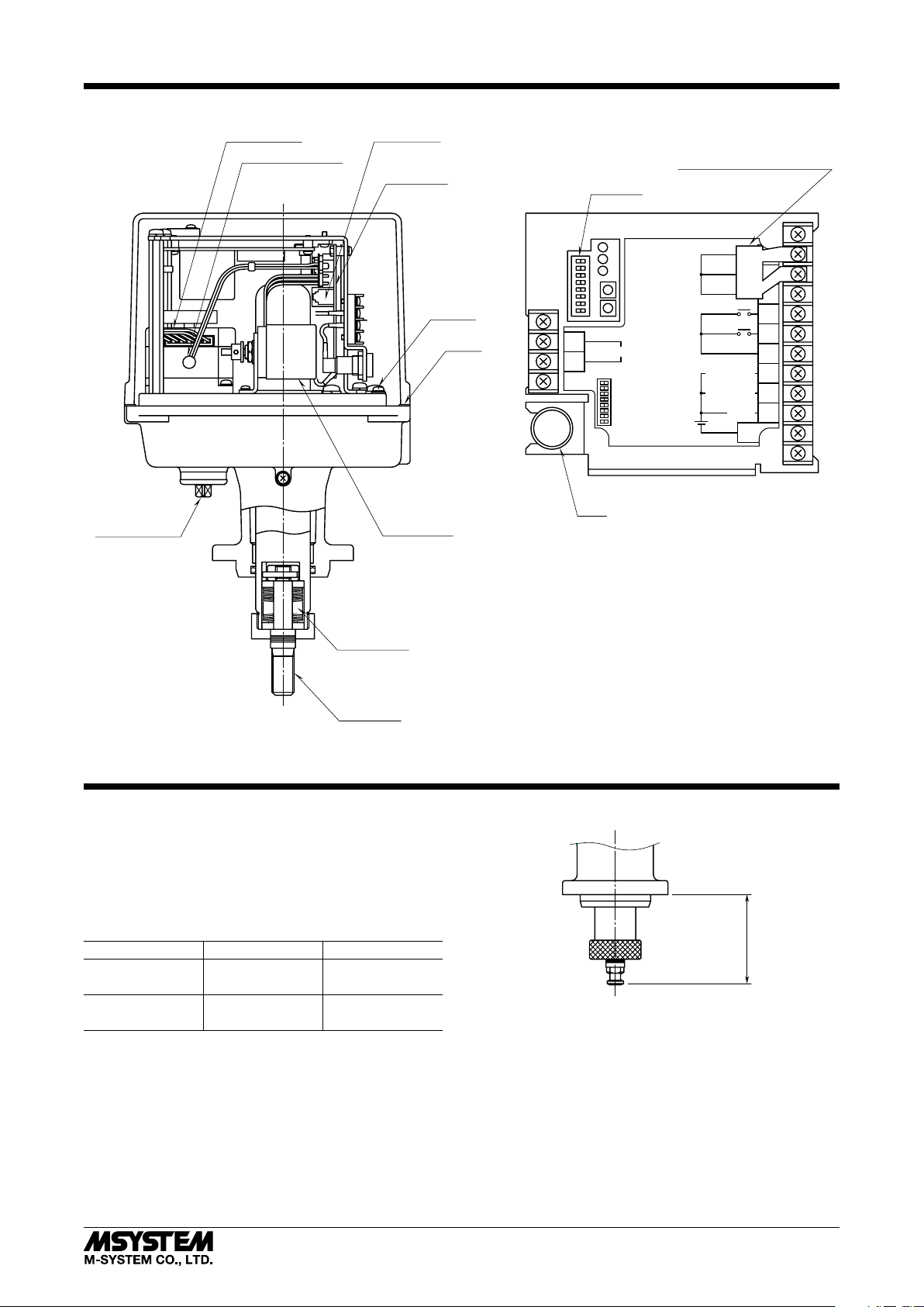
COMPONENT IDENTIFICATION
Stepping Motor
Temperature Sensor
Modular Jack
Control PCB
PSN1 / PSN3
Input Resistor (for current input)
SW-1 –8
Manual Operation
Angle Sensor
Sealing Spring
Ground
Terminal
Gasket
FUSE
POWER
INPUT
ALARM
UP
DOWN
1
2
U(+)
POWER
V(–)
1 EXTEND / RETRACT
2 ACCORDING TO SW1 / STOP
3 REVERSE / DIRECT
4
5 RETRACTED POSITION SET
6 EXTENDED POSITIN SET
7
8 RUN / PU
POWER
INPUT
ALARM
UP
(RETRACT)
DOWN
(EXTEND)
OPEN / CLOSE
SEQUENTIAL
INPUT
SIGNAL
POSITION
SIGNAL
FORCED
COMMAND
CONTROL
+
COM1
+
RETRACT
EXTEND
OPEN / CLOSE SIGNAL
RETRACTED
OPEN / CLOSE SIGNAL
EXTENDED
ALARM
COM2
COM1
12
3
4
5
6
7
8
9
10
11
Fuse
: Power LED (green LED turns on when applied)
: Input LED (green LED turns on when applied)
: Alarm LED (red LED turns on with alarm)
: UP Control Button
: DOWN Control Button
Output Stem
Figure 1. Component Identication
OUTPUT STROKE & ADJUSTABLE RANGE
The servo-control PCB compares input signal (position setpoint signal) and actual position signal from the position
sensor, and drives the motor to reduce the deviation.
When a full-close signal is provided, the output stem is
pressed onto the sealing spring after the valve is fully
closed, until the sealing pressure reaches a preset value.
MODEL L (mm) L (inch)
PSN1-4x1 66 to 106 2.60 to 4.17
PSN1-4x2 52 to 92 2.05 to 3.62
PSN3-6x1 66 to 126 2.60 to 4.96
PSN3-6x2 52 to 112 2.05 to 4.41
Yoke Surface
L
Figure 2. Operational Range of the Output Stem
5-2-55, Minamitsumori, Nishinari-ku, Osaka 557-0063 JAPAN
Phone: +81(6)6659-8201 Fax: +81(6)6659-8510 E-mail: info@m-system.co.jp
EM-4857 Rev.10 P. 3 / 9
Page 4

PSN1 / PSN3
INSTALLATION
Valve, yoke and other components necessary to connect the
PSN to the valve are provided by the customer.
DO NOT CHANGE the ex-factory settings of the PSN. The
following procedure should be done with the power supply
removed, except when otherwise specified.
(General Procedure)
1) Apply power input and 0% input signal (100% for direct
action) in order to expose the output stem to the maximum degree.
2) Set the valve stem at the lowest position.
3) Connect the PSN to the yoke.
4) Screw the valve stem into the output stem until there is
little opening between them.
For applying a sealing pressure, refer to flexure values in
Table 3 (e.g. 1 mm for applying 1500 N for PSN1-x1) and
screw it until the opening equals the value.
5) Fix both stems with a lock nut.
6) Apply power input and approx. 50% input signal and
check that there is no opening between the yoke and
valve bonnet.
Fix the yoke and the valve.
7) Connect the indicator and other components if necessary.
SERVO-TOP II
Bolt
Output Stem
Indicator
Scale Plate
Valve Stem
Button
Lock Nut
Yoke
Valve Bonnet
40°
40°
ø9 (.35)
ø14 (.55)
Figure 3. Stem Details
ø15 (.59)
140°
ø10
(.39)
ø15 (.59)
R1
6 (.24)4 (.16)
1 (.04)
6 (.24)
16 (.63)
Figure 5. Connecting the PSN with a Valve, Example
ELECTRICAL CONNECTIONS
Remove the cover of the PSN body and wire to the terminal
block according to Figure 6.
The PSN requires the power input (1 – 2) and input signal
(3 – 4) connections for operating.
INPUT SIGNAL
POSITION SIGNAL
FORCED
OPEN/CLOSE
COMMAND
SEQUENTIAL
CONTROL
+
3
*
R
COM1
RETR.
EXT.
(EXT.)
COM2
4
5
MODULAR JACK
+
8
6
7
9
10
11
12
COM1
FULL OPEN
/CLOSE
(RETR.)
ALARM
*Input resistor attached for a current input.
APPLICABLE SOLDERLESS TERMINAL
3.2 (.13) dia min.
U(+)
1
2
POWER
V(–)
PU-2x
Figure 4. Indicator Details
5-2-55, Minamitsumori, Nishinari-ku, Osaka 557-0063 JAPAN
Phone: +81(6)6659-8201 Fax: +81(6)6659-8510 E-mail: info@m-system.co.jp
5.9 (.23)
4.6 (.18) min.
Figure 6. Connection Diagram
EM-4857 Rev.10 P. 4 / 9
max.
Page 5

ADJUSTMENT PROCEDURE
Open the PSN body cover and adjust the full-open and
-closed positions referring to Figure 1. Other adjustments
can be also conducted as explained below: switching actuator action, safety operation at abnormally low input, and
positions for the open/close limiters and for the full-open/
close signal, and restart limiting timer.
For adjusting positions for the open/close limiters and for
the full-open/close signal, and restart limiting timer, the
PU-2x is required.
■ OPERATION AT ABNORMALLY LOW INPUT (SW-1, SW-2)
When the input goes down to 0.37±0.1V DC or below, the
PSN goes to the abnormal low input operation. It is set to
stop the actuator at the factory. Refer to Table 1.
PSN1 / PSN3
■ FULL-OPEN/CLOSED POSITIONS
1) Turn ON the SW-8 in order to put the PSN in the local
calibration mode, and the input signal is disregarded.
2) Turn ON the SW-5 and adjust the fully retracted end
pressing UP/DOWN control buttons.
3) When the output stem reaches a desired position, turn
OFF the SW-5. The position is memorized as the fully
retracted end.
4) Turn ON the SW-6 and adjust the fully extended end
pressing UP/DOWN control buttons.
5) When the output stem reaches a desired position, turn
OFF the SW-6. The position is memorized as the fully
extended end.
6) Turn OFF the SW-8 in order to put the PSN in the operating mode. Apply input signals and confirm the fullopen/closed positions.
Table 1. Abnormal low input operation & switch positions
MODE SW-1 SW-2
Stop
Fully Extend
Fully Retract
*1
OFF
ON
ON
OFF
OFF
*1. SW-1 position is disregarded in STOP mode.
SW-1...SW-8
O
1
N
2
3
4
5
6
7
8
UP Control Button
DOWN Control Button
FUSE
U(+)
1
V(–)
2
POWER
INPUT
ALARM
POSITION SIGNAL
UP
DOWN
FORCED
OPEN/CLOSE
POWER
COMMAND
SEQUENTIAL
CONTROL
1 CLOSE/OPEN
2 ACCORDING TO SW1/STOP
3 REVERSE/DIRECT
4
5 FULL-OPEN POSITION SET
6 FULL-CLOSED POSITION SET
7
8 RUN/PU
INPUT SIGNAL
COM1
OPEN
CLOSE
COM1
FULL OPEN
FULL CLOSE
ALARM
COM2
12
+
3
4
–
5
6
7
8
9
10
11
Figure 7. Adjustments, Details
■ ACTUATOR ACTION (SW-3)
Use SW-3 for switching the actuator action. It is set to “REVERSE” at the factory. Refer to Table 2.
Table 2. Actuator action
MODE SW-3 ACTION
Direct ON Output stem retracted with decreasing
input. (Valve stem pulled out.)
Reverse OFF Output stem extended with decreas-
ing input. (Valve stem pushed in.)
In DIRECT action, the input signal 0 – 100% corresponds to
the position output signal 20 – 4mA DC.
■ SEALING SPRING
For applying a sealing pressure when the valve is fully
closed, adjust flexure of the sealing spring when calibrating
the fully opened/closed positions.
For applying a sealing pressure at the both ends, such like
the case of a three-way valve, adjust flexure of the sealing
spring at the both ends.
Excessive flexure may shorten life of the actuator and
spring. Observe the maximum flexure at the maximum
pressure.
The output stem is provided with scales by millimeters.
Output Stem
Sealing Pressure
Scale
Figure 8. Sealing Spring
TYPE MAXIMUM
PRESSURE
1500 N use
3000 N use
5000 N use
1500 N use
3000 N use
5000 N use
(N)
1500
3000
5000
(lb)
337
674
1124
FLEXURE AT
MAXIMUM
PRESS. (mm)
1
1
0.5
(inch)
0.04
0.04
0.02
SET
PRESS.
(N)
1170
2410
3980
(lb)
263
542
895
RATED
SPRING
(N/mm)
330
590
2040
(lb/in.)
1880
3370
11600
Note: The seal spring starts flexing when a pressure exceeding
the set pressure is applied. Control pressure within 80%
of the set pressure except when the valve is fully closed.
If excessive pressure is applied within the control range,
flexure of the spring may jeopardize the linearity.
5-2-55, Minamitsumori, Nishinari-ku, Osaka 557-0063 JAPAN
Phone: +81(6)6659-8201 Fax: +81(6)6659-8510 E-mail: info@m-system.co.jp
EM-4857 Rev.10 P. 5 / 9
Page 6

PU-2x ADJUSTMENTS
■ DISPLAY
ITEM No.
G
I
D
• Response Messages
NG: No good
The PU-2x may not be securely connected.
Check connection of the modular jack.
ER: Communication error
Turn the SW-8 ON.
• Data Indicator
OK: OK
DATA-ERR: Invalid data input
NON-ITEM: ITEM No. not applicable
■ PROGRAMMABLE ITEMS
Table 4. Programmable items ( ) for PSN3
ITEM
No.
ITEM
10 Full-open/-closed
position (retracted)
11 Full-open/-closed
position (extended)
12 Retracted side limit 75 – 105 0.1 100
13 Extended side limit -5 – 25 0.1 0
14 Full-open/-closed
output (retracted)
15 Full-open/-closed
output (extended)
16 Split ON/OFF 0 or 1 0
17 Split type LO/HI 0 or 1 0
18 Split point 30 – 70 0.1 50
19 Opening/closing
speed limit
20 Deadband 0.1 – 5 0.1 0.5
21 Restart limiting timer 0 – 30*
22 Speed in shutdown*
23 Position in shutdown*
*2. ROM version 1.05 or later
*3. Settings are enabled with ‘Failsafe’ option.
■ ROM VERSION INDICATION
Press ITEM 99 in the local calibration mode in order to display the ROM version of the PSN.
■ HOW TO PROGRAM THE PSN
1) Apply power supply voltage to the PSN.
2) Turn ON the SW-8 in order to put the PSN in the local
calibration mode, and the input signal is disregarded.
3) Connect the modular jack cord of the PU-2x to the PSN.
ITEM display is blank.
4) Indicating Current Setting
Key in the ITEM No. that you want to check. (N = 0 to 9)
Press [ITEM] [N] [N].
Response Messages
()
Data to be entered
or Messages
USABLE
RANGE
MINIMUM
INCREMENT
8 – 100 0.1 100
0 – 92 0.1 0
75 – 100 0.1 98
0 – 25 0.1 2
1 – 50 1 16 (24)
2
3
1 – 50 1 16 (24)
3
0 – 100 0.1 0
LCD Display
2
0.1*
DEFAULT
2
PSN1 / PSN3
5) Indicating New ITEM No.
Press [ITEM] [N] [N] or press [UP] or [DOWN].
6) Modifying Current Setting
Display the ITEM No. that you want to change, and press
[DATA], new setting, and [ENTER].
If an irrelevant setting is entered, the PU-2x indicates
“DATA-ERR” on its message display. Key in an appropriate setting again.
7) Remove the modular jack cord of the PU-2x.
8) Turn OFF the SW-8 in order to return the PSN in the
operating mode. Apply input signals and confirm every
setting.
Note 1: DO NOT remove power to the PSN with the PU-2x
connected to it.
Note 2: Be sure to remove the PU-2x before driving the motor
(in the operating mode).
■ EXPLANATIONS ABOUT THE PROGRAMMABLE ITEMS
1) Full-Open/-Closed Positions (ITEM No.10, 11)
Key in a percentage value within 0% for the extended
end, and 100% for the retracted end.
[Extended End] > [Retracted End]
2) Extended/Retracted Limits (ITEM No.12, 13)
The adjustable ranges shown in Table 4 are applicable
against the stroke determined by the full-open/-closed
positions as 100%.
3) Full-Open/-Closed Outputs (ITEM No.14, 15)
The adjustable ranges shown in Table 4 are applicable
against the stroke determined by the full-open/-closed
positions as 100%.
4) Split Range (ITEM No.16 to 18)
Refer to Figure 9 and determine the type and point of
split range.
When the split range is set to OFF (ITEM No.16), the
split range type and point (ITEM No.17, 18) are invalid.
Split Range Type Set to “LO”
(Set to “DIRECT” Action)
Split Range Type Set to “HI”
(Set to “REVERSE” Action)
Retracted End
OUTPUT STEM
Extended End
POSITION
0
INPUT (%)
30 70
Figure 9. Split Range
Thick, solid lines indicate
examples of I/O characteristics,
while broken lines indicate
limits of adjustable range.
100%50
Adjustable Split Point Range
5-2-55, Minamitsumori, Nishinari-ku, Osaka 557-0063 JAPAN
Phone: +81(6)6659-8201 Fax: +81(6)6659-8510 E-mail: info@m-system.co.jp
EM-4857 Rev.10 P. 6 / 9
Page 7

PSN1 / PSN3
5) Opening/Closing Speed Limit (ITEM No.19)
Opening/closing speed affects the thrust. Refer to Tables
5 – 6 and Figures 10 – 11 for checking required thrust
and attainable speed.
Acceleration or deceleration is not included in the speed.
Acceleration or deceleration respectively requires approx. 0 to 2 sec.; takes longer with faster speed.
Table 5. PSN1 opening/closing speed limit
SPEED
SCALE [A]
SPEED [V]
(mm/s)
OPERATION
TIME (s/20 mm)
THRUST
N lb
1 0.30 66.0 3000 674
2 0.54 37.3 3000 674
16 2.03 9.9 3000 674
35 4.05 4.9 2500 562
44 5.01 4.0 2000 450
50 5.65 3.5 1600 360
Speed [V] achieved by Speed Scales [A] other than mentioned
above can be approximately calculated by the following equation:
Speed [V] = 0.106 × Speed Scale [A] + 0.323, where 2 ≤ A ≤ 50
Table 6. PSN3 opening/closing speed limit
SPEED
SCALE [A]
SPEED [V]
(mm/s)
OPERATION
TIME (s/20 mm)
THRUST
N lb
1 0.22 92.6 5000 1124
2 0.38 52.3 5000 1124
10 0.99 20.2 5000 1124
13 1.22 16.4 4500 1012
16 1.44 13.8 4000 899
20 1.75 11.4 3500 787
24 2.05 9.7 3000 674
28 2.35 8.5 2500 562
33 2.73 7.3 2000 450
36 2.96 6.8 1500 337
41 3.34 6.0 1000 225
48 3.87 5.2 500 112
50 4.02 5.0 350 79
Speed [V] achieved by Speed Scales [A] other than mentioned
above can be approximately calculated by the following equation:
Speed [V] = 0.076 × Speed Scale [A] + 0.231, where 2 ≤ A ≤ 50
3500
3000
2500
2000
1500
THRUST (N)
1000
500
Thrust
Speed
7
6
5
4
3
SPEED (mm/s)
2
1
6000
Thrust
5000
4000
3000
THRUST (N)
2000
1000
0
02010 30 40 50
SPEED SCALE
Speed
5
4
3
SPEED (mm/s)
2
1
0
Figure 11. PSN3 Speed v.s. Thrust
6) Deadband (ITEM No.20)
Deadband is adjustable as % of the maximum stroke
within 0.1 to 5%.
7) Restart Limiting Timer (ITEM No.21)
The timer is provided to protect the motor from overheat-
ing, preventing it from restarting for a certain interval
once the motor has been stopped within deadband.
When the high temperature protection is activated in a
high temperature ambient, adjust the timer to a longer
interval.
Adjustable range is within 0 to 30 sec.
MANUAL OPERATION
■ WHEN POWER IS AVAILABLE TO SUPPLY TO PSN
1) Turn on the power supply.
2) Turn on the SW-8 to put the PSN into the local calibration mode.
3) Use UP/DOWN buttons to manually operate the PSN.
4) Turn off the SW-8 after turning off the power supply.
■ USING THE MANUAL OPERATION STEM
1) Be sure that the power supply is removed.
2) The output stem is designed to go up when the manual
operation stem turns clockwise (seen from the operation
stem side). Turn the handle with a torque under 1 N·m
or 0.74 ft·lb (1.5 N·m or 1.48 ft·lb for PSN3) in checking
the stem position with the indicator.
3) The output stem moves by 10 mm per approx. 24 turns
(approx. 25 turns for PSN3) of the manual operation
stem.
4) When the operation is completed, be sure to remove the
handle and cover the stem with a rubber cap.
5) Be sure that the handle is not attached before turning on
the power supply.
6) Use a 8-mm spanner as a handle.
0
02010 30 40 50
SPEED SCALE
Figure 10. PSN1 Speed v.s. Thrust
5-2-55, Minamitsumori, Nishinari-ku, Osaka 557-0063 JAPAN
Phone: +81(6)6659-8201 Fax: +81(6)6659-8510 E-mail: info@m-system.co.jp
0
EM-4857 Rev.10 P. 7 / 9
Page 8

PROTECTIVE FUNCTIONS
■ ERROR DETECTION
• When the position signal is deviated from the input signal but the output stem is stuck due to overload or certain
malfunction, the PSN repeats starting the motor at the
maximum torque for several items. If the stem is still
stuck after that, the PSN outputs an alarm signal (LED
turned ON) and stops power supply to the motor.
• In order to reset the PSN, apply several times 0% and
100% input signals in turn, or turn off and on the power
supply.
• In case the alarm is off frequently, check for foreign obstacles in the valve, inappropriate adjustments, or retightened gland packing or other possible causes of the
overload.
• e sure to remove the cause of alarm in order to ensure
appropriate life span.
■ ABNORMAL TEMPERATURE INCREASE PROTECTION
• When the incorporated temperature sensor detects an abnormal temperature increase in the motor, the PSN outputs an alarm signal (LED blinks in 0.5-sec. ON – 0.5-sec.
OFF sequence) and stops power supply to the motor until
the temperature decreases to an acceptable level.
• The PSN is designed to automatically recover power supply to the motor. It take longer to recover normal operation when ambient temperature is higher.
PSN1 / PSN3
■ PROTECTIVE FUSE
• A fuse is incorporated for protection against overcurrent
in the control PCB and motor.
• If the power LED does not turn on with the power supplied to the actuator, check the fuse status.
• If a replaced fuse is blown quickly, it is possible that the
control PCB and/or motor are damaged. Consult M-System or M-System’s representative.
■ MOTOR PREHEAT FUNCTION
When the PSN detects a temperature lower than 0°C or
32°F (approximate) on the surface of its motor, the PSN supplies current to the motor in order to warm up and maintain
its surface temperature at 5°C or 41°F (approximate).
Maintain the power supply ON when the PSN is used in the
ambient temperature below 0°C or 32°F.
MAINTENANCE
For effective use and longer life of the PSN, regular checking appropriate for its operating conditions are recommended. Refer
to the following table.
ITEM CHECKING POINT HOW TO PROCEED
Functioning Apply input 0%, 50%, 100%, then back to 50%, 0%.
Check the actuator operations and positions at each
input value.
Abnormal sound No abnormal sound is heard during operation. Repair or calibration
Connector
Leadwire
Inside humidity, rust No condensation. No rust.
Screws Check that screws and bolts are securely fastened. Re-tighten them.
Nut Check that the nut at the valve stem is not loose. Re-tighten it and calibrate.
The connector is firmly connected.
No breakdown of leadwires.
The insulation covers are not torn, not bruised.
If there is water inside, check the packing.
For repair or parts replacement, contact M-System or representatives.
■ LUBRICATION
There is no need of oiling the PSN in normal operating conditions.
■ REGULAR TEST RUNNING
If the valve is not frequently operated, run a test operation regularly (once a week, for example) to check proper functions.
Repair or calibration
If the alarm indicator LED is on, check that the
valve operates lightly and smoothly.
Repair or calibration
Remove water, dry the case and inside parts.
Replace rusted parts. Calibration.
If the packing is damaged, replace it.
5-2-55, Minamitsumori, Nishinari-ku, Osaka 557-0063 JAPAN
Phone: +81(6)6659-8201 Fax: +81(6)6659-8510 E-mail: info@m-system.co.jp
EM-4857 Rev.10 P. 8 / 9
Page 9

PSN1 / PSN3
TROUBLESHOOTING
TROUBLE POSSIBLE CAUSE HOW TO PROCEED
Not functioning Power and/or
input indicator
OFF
Power and input
indicator ON
Unstable functioning Operating speed is too fast. Secure the required thrust by slowing.
Alarm indicator ON Overload caused by a foreign object caught
Alarm indicator blinking Motor temperature is abnormally high. Use the restart limiting timer. Review MV
For repair or parts replacement, contact M-System or representatives.
Power and/or input signal is not supplied. Check power and input signals, remove the
causes of malfunction and secure the sig-
nals.
Wiring error. Check the wiring.
Bad contact. Check the connector and other connecting
sections.
Fuse melted. Replace it with a new one.
The actuator is in local calibration mode
(SW-8 ON).
Improper adjustments of full-open/-closed
positions.
Control PCB damaged. Repair and calibration.
Motor damaged. Repair and calibration.
Abnormality in power voltage or input
signal.
Power voltage is too low or fluctuating. Secure the required level of voltage.
Input is unstable. Check the controller and cables. Eliminate
Angle sensor is damaged. Repair and calibration.
in the valve.
Actuator mechanism damaged. Repair and calibration.
Wiring of the temperature sensor is broken
or the connector is detached.
Turn SW-8 OFF.
Adjust the full-open/-closed positions.
Remove the causes of malfunction and
secure the signals.
noise.
Remove the causes of overload.
value from the controller.
Check the connector and leadwires.
LIGHTNING SURGE PROTECTION
M-System offers a series of lightning surge protectors for
protection against induced lightning surges. Please contact
M-System to choose appropriate models.
5-2-55, Minamitsumori, Nishinari-ku, Osaka 557-0063 JAPAN
Phone: +81(6)6659-8201 Fax: +81(6)6659-8510 E-mail: info@m-system.co.jp
EM-4857 Rev.10 P. 9 / 9
 Loading...