

Page 1
INSTRUCTION MANUAL
LIGHTNING SURGE PROTECTOR FOR
LONWORKS (FTT-10A)
BEFORE USE ....
Thank you for choosing M-System. Before use, please check
contents of the package you received as outlined below.
If you have any problems or questions with the product,
please contact M-System’s Sales Office or representatives.
■ PACKAGE INCLUDES:
Surge protector ....................................................................(1)
DIN rail mounting adaptor* ...............................................(1)
Screws for DIN rail mounting (M4 × 8)* ...........................(2)
*Included with option code /A33
■ MODEL NO.
Confirm Model No. marking on the product to be exactly
what you ordered.
■ INSTRUCTION MANUAL
This manual describes necessary points of caution when
you use this product, including installation, connection and
basic maintenance procedures.
LIMITATION APPLICABLE TO M-RESTER
The M-RESTER will protect electronics equipment from
damage caused by lightning by absorbing most of the
surge voltages.
However, M-RESTER may not be effective against certain extremely high voltages caused by a direct or almost
direct hit by lightning.
M-RESTER must be installed according to this installation / instruction manual.
GENERAL
■ FUNCTION & FEATURES
• Designed specifically for L
• No interruption of transmission signal by unplugging the
head element module
■ SPECIFICATIONS
Max. continuous
operating voltage (Uc)
Voltage protection level
(Up) @2kV (1kA)
Leakage current ≤ 0.15mA
Capacitance @1 MHz ≤ 200 pF ≤ 200 pF ≤ 30 pF
Response time ≤ 4 nsec. ≤ 20 nsec. ≤ 20 nsec.
Max. discharge current
(Imax)
Nominal current (IN) 100mA
Internal series resistance
Max. line voltage ±1.5V
Input attenuation
ONWORKS network
LINE TO
LINE
±1.5V ±100V ±160V
±40V ±350V ±650V
@±1.5V
-1 dB or less @DC...100 kHz, Z0 = 50 Ω
LINE TO
EARTH
≤ 20µA
@±100V
5000A (8 / 20 µs)
≤ 3.3 Ω including return
SHLD TO
EARTH
≤ ±20µA
@±160V
MODEL
MDP-LWA
POINTS OF CAUTION
■ ENVIRONMENT
• When heavy dust or metal particles are present in the
air, install the surge protector inside proper housing with
sufficient ventilation.
• Do not install the surge protector where it is subjected to
continuous vibration. Do not subject the unit to physical
impact.
• Environmental temperature must be within -5 to +55°C
(23 to 131°F) with relative humidity within 30 to 90% RH
in order to ensure adequate life span and operation.
■ NETWORK SPECIFICATIONS
• The MDP-LWA is applicable to networks which consist
only of FTT-10A. Not applicable to the ones connected to
Link Power network.
• For detailed information on the network, refer to L
ON-
WORKS FTT-10A Free Topology Transceiver User’s Guide
provided by Echelon.
■ DIELECTRIC STRENGTH TEST
• Loosen the screw located at the left-center of the element
and remove the element module from the base before
conducting a dielectric strength testing. Otherwise the
element will start discharging at a voltage exceeding the
max. continuous operating voltage (Uc), which can cause
insulation failure of the module.
Be sure to return the element and fasten securely after
the test.
■ AND ....
• We recommend that you keep spare surge protectors so
that you can replace them when necessary.
• Lightning surge can enter not only through signal lines
but also through power supply lines. We recommend that
you also use the surge protectors for power line for sufficient protection.
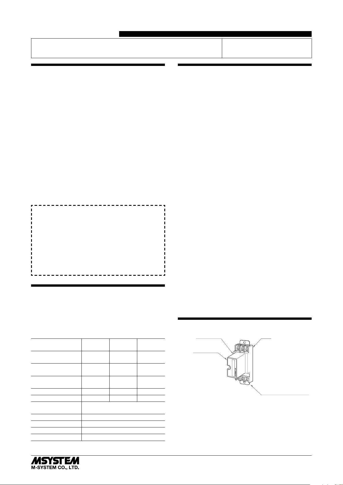
COMPONENT IDENTIFICATION
Head Element
Specifications
Lot.NO
M•RESTER
MODEL
Element is secured to Base
with screw when M-RESTER is
shipped from Factory.
MADE IN JAPAN N1430B
Base
Ground Terminal (G)
(used as mounting bracket)
5-2-55, Minamitsumori, Nishinari-ku, Osaka 557-0063 JAPAN
Phone: +81(6)6659-8201 Fax: +81(6)6659-8510 E-mail: info@m-system.co.jp
EM-8234 Rev.2 P. 1 / 4
Page 2
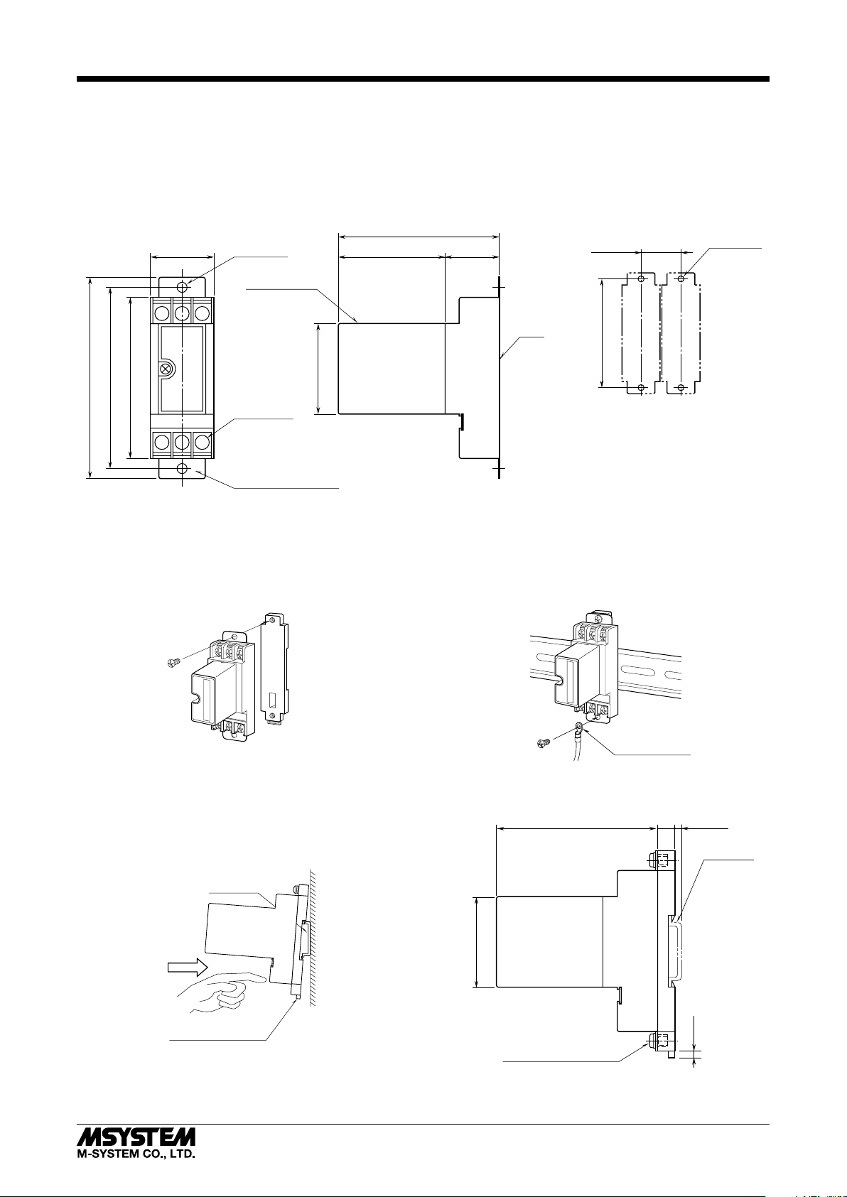
INSTALLATION
(used as mounting bracket)
80 (3.15)
BASE
100 (3.94)
In order to separate the head element from the base, loosen the screw located at the left-center of the element.
■ WALL MOUNTING
Refer to the drawings below.
MDP-LWA
• EXTERNAL DIMENSIONS unit: mm (inch)
31.5 (1.24)
2–5 (.20) dia.
MTG HOLE
HEAD ELEMENT
23
1
80 (3.15)
90 (3.54)
45 (1.77)
6–M4 SCREW
C
B
A
GROUND TERMINAL (G)
■ DIN RAIL MOUNTING (Only for /A33)
1. MOUNTING ONTO THE ADAPTOR
Before DIN rail mounting, secure the mounting bracket of
MDP to the mounting adaptor with a screw provided with
this product. In this step, secure at one point.
• MOUNTING REQUIREMENTS
unit: mm (inch)
27 (1.06)53 (2.08)
33 (1.30) min.
90 (3.54)
2–M4 SCREW
3. GROUNDING
Secure the mounting bracket at the other point with the
other screw. In this step, secure the grounding wire together with the screw.
M•RESTER
2. DIN RAIL MOUNTING
Set the base socket so that its mounting slider is at the bottom. Position the upper hook at the rear side of base socket
on the DIN rail and push in the lower. When removing the
socket, push down the mounting slider utilizing a minus
screwdriver and pull.
DIN Rail
35 mm wide
DIN Rail Mounting Slider
M•RESTER
Solderless Terminal
• MOUNTING REQUIREMENTS unit: mm (inch)
80 (3.15)
8.5
[3.3 (.13)]
(.33)
45 (1.77)
4
2–M4 MOUNTING SCREW
(used as ground terminal (G))
DIN RAIL
35mm wide
(.18)
5-2-55, Minamitsumori, Nishinari-ku, Osaka 557-0063 JAPAN
Phone: +81(6)6659-8201 Fax: +81(6)6659-8510 E-mail: info@m-system.co.jp
EM-8234 Rev.2 P. 2 / 4
Page 3

MDP-LWA
TERMINAL CONNECTION
Connect the unit as in the diagram below.
Be sure to cross-wire between the Ground terminal (G) and that of the protected equipment. When the surge protector is connected with a device which has no ground terminal such like M-System’s (See figure below), ground the M-RESTER Ground
terminal (G) only.
*1
1
A
3
C
2
B
G
Grounding
*1. Be sure to use twisted-pair cables.
*2. No polarity.
*3. With shielded twisted-pair cables, connect the shield to the surge protector’s B terminal.
Follow instructions provided with the protected device whether 2 terminal should be
connected or not. However, if the shield terminal of the protected device is not isolated
from NET A / B, DO NOT connect 2 terminal to the protected device.
Protected DeviceMDP-LWA
*2
*3
Cross wiring
SHLD
NET
A, B
G
■ NETWORK CONFIGURATION
Panel / Cabinet
MDP-LWA
Protected SideSurge Side
Network CableNetwork Cable
G G
Crossover Wire
■ GROUNDING
M-RESTER
G
GROUNDING
(100 ohms or less)
A crossover wire between M-RESTER ground and the ground or
metallic housing of the equipment is required for protection.
If the protected equipment has no ground terminal, ground the
M-RESTER only.
When the M-RESTER is mounted with DIN Rail Mounting Adapter,
connect the grounding wire to the mounting screw of the M-RESTER.
Protected
Devices
(Nodes)
PROTECTED
EQUIPMENT
G
CROSSOVER WIRE
G
Grounding
Panel / Cabinet
MDP-LWA
Protected SideSurge Side
Network Cable
G G
Crossover Wire
Protected
Devices
(Nodes)
G
•The MDP-LWA is applicable to networks which consist only of FTT-10A.
Not applicable to the ones connected to Link Power network.
• The maximum number of nodes connectable to the network segment is reduced by one
when one unit of MDP-LWA is added.
• When the distance between nodes are relatively long (e.g. grouped and separated by cabinets),
install the MDP-LWA by each group of devices. Insert the MDP-LWA at the surge side of the network.
• For detailed information on the network, refer to L
User’s Guide provided by Echelon.
ONWORKS FTT-10A Free Topology Transceiver
5-2-55, Minamitsumori, Nishinari-ku, Osaka 557-0063 JAPAN
Phone: +81(6)6659-8201 Fax: +81(6)6659-8510 E-mail: info@m-system.co.jp
EM-8234 Rev.2 P. 3 / 4
Page 4

WIRING INSTRUCTIONS
■ SCREW TERMINAL
Torque: 0.8 N·m
MAINTENANCE
Check surge protectors periodically. Many cases of lightning are ignored, and even lightning at a far distance often
causes inductive surges.
We recommend that you check your surge protector about
twice a year, before and after the rainy season. Check
whenever you experience a strong lightning occurrence.
Checking procedure is explained in the following:
■ CHECKING
WIRING
1) Make sure that wiring is done as instructed in the connection diagram.
2) Make sure that the Ground terminal (G) is connected to
the metallic housing of protected equipment.
3) Make sure that the Ground terminal (G) is grounded to
earth.
MDP-LWA
DISCHARGE FUNCTION
The M-RESTER Tester is available for a preliminary checking of the surge protector’s head element.
Approximate testing procedure without using the Tester is
explained as below.
1) Remove all wiring connected to the surge protector when
you test the element module.
2) Check resistance across the following terminals on the
high resistance range of multimeter (≤ 1V) and confirm
no conduction. The meter shows a value equivalent to
open circuit.
Terminals (A) – (B), (A) – (C), (B) – (C)
3) Check that discharging occurs across the same terminals
with a 500V DC 1000MΩ insulation tester (The tester
shows ≤ 20MΩ).
If any of the above tests shows negative, replace the protector.
(A) – (G), (B) – (G), (C) – (G)
5-2-55, Minamitsumori, Nishinari-ku, Osaka 557-0063 JAPAN
Phone: +81(6)6659-8201 Fax: +81(6)6659-8510 E-mail: info@m-system.co.jp
EM-8234 Rev.2 P. 4 / 4
 Loading...