

Page 1
5-2-55, Minamitsumori, Nishinari-ku, Osaka 557-0063 JAPAN
Phone: +81(6)6659-8201 Fax: +81(6)6659-8510 E-mail: info@m-system.co.jp
EM-8258 Rev.2 P. 1 / 3
INSTRUCTION MANUAL
LIGHTNING SURGE PROTECTOR FOR
STANDARD SIGNAL LINE & PULSE USE (life monitor)
MODEL
MDPA-24
MDPA-65
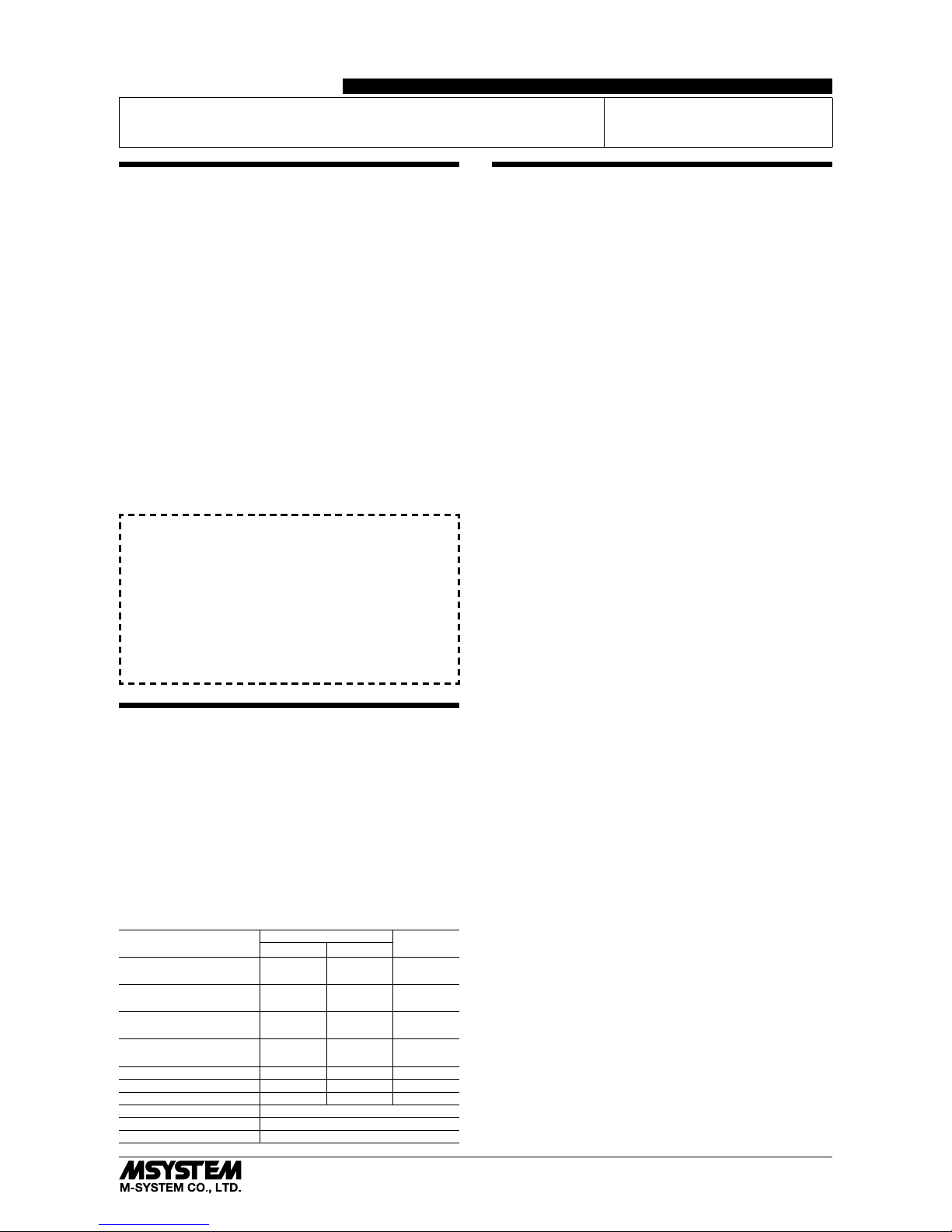
BEFORE USE ....
Thank you for choosing M-System. Before use, please check
contents of the package you received as outlined below.
If you have any problems or questions with the product,
please contact M-System’s Sales Office or representatives.
■ PACKAGE INCLUDES:
Surge protector (Head element + Base) ........................... (1)
DIN rail mounting adaptor* .............................................. (1)
Screws for DIN rail mounting (M4 × 8)* .......................... (2)
*Included with option code /A33
(Base section is optional.)
■ MODEL NO.
Confirm Model No. marking on the product to be exactly
what you ordered.
■ INSTRUCTION MANUAL
This manual describes necessary points of caution when
you use this product, including installation, connection and
basic maintenance procedures.
LIMITATION APPLICABLE TO M-RESTER
The M-RESTER will protect electronics equipment from
damage caused by lightning by absorbing most of the
surge voltages.
However, M-RESTER may not be effective against certain extremely high voltages caused by a direct or almost
direct hit by lightning.
M-RESTER must be installed according to this installation / instruction manual.
GENERAL
■ FUNCTION & FEATURES
• Designed specifically for 4 – 20mA DC and pulse signal
line including both 4-wire and 2-wire transmitters
• Life monitor function helps you to decide when you
should replace the surge protector; reduces maintenance
and prevents downtime
• Pressing CHK (Check) button confirms the degradation
and life span of the surge protection circuits with LEDs
• Absorbs surges only without affecting instrumentation signal
• No interruption of signal by unplugging surge protector element
■ SPECIFICATIONS
LINE TO LINE LINE TO
EARTH
MDPA-24 MDPA-65
Max. continuous
operating voltage (Uc)
30V 70V ±160V
Voltage protection level
(Up) @1kV (100A)
45V 85V ±650V
Voltage protection level
(Up) @2kV (1kA)
50V 100V ±650V
Leakage current
(new device)
≤ 5µA
@30V DC
≤ 5µA
@70V DC
≤ 5µA
@±140V DC
Capacitance @1 MHz ≤ 1000 pF ≤ 1000 pF ≤ 100 pF
Response time ≤ 4 nsec. ≤ 4 nsec. ≤ 20 nsec.
Max. line voltage 30V 70V ---Max. discharge current (Imax)
5000A (8 / 20 µs)
Nominal current (I
N) 100mA
Internal series resistance
20 Ω ±10% including return
POINTS OF CAUTION
■ ENVIRONMENT
• Indoor use.
• When heavy dust or metal particles are present in the
air, install the surge protector inside proper housing with
sufficient ventilation.
• Do not install the surge protector where it is subjected to
continuous vibration. Do not subject the unit to physical
impact.
• Environmental temperature must be within -5 to +55°C
(23 to 131°F) with relative humidity within 30 to 85% RH
in order to ensure adequate life span and operation.
■ WIRING
• Do not install cables close to noise sources (relay drive
cable, high frequency line, etc.).
• Do not bind the surge protector’s cables together with
those in which noises are present. Do not install them in
the same duct.
■ DIELECTRIC STRENGTH TEST
• Loosen the screw located at the left-center of the element
and remove the element module from the base before
conducting a dielectric strength testing. Otherwise the
element will start discharging at a voltage exceeding the
max. continuous operating voltage (Uc), which can cause
insulation failure of the module.
Be sure to return the element and fasten securely after
the test.
■ BATTERY LIFE
• The battery’s life is assured for 10 years from the manufacturing date indicated at the right-top of the specification label (when used ≤ 2 minutes/month).
• The battery continues to discharge even while it is unused. We recommend not to store the Element module for
a long period of time.
■ AND ....
• We recommend that you keep spare surge protectors so
that you can replace them when necessary.
• Lightning surge can enter not only through signal lines
but also through power supply lines. We recommend that
you also use the surge protectors for power line for sufficient protection.
Page 2
MDPA-24 / MDPA-65
5-2-55, Minamitsumori, Nishinari-ku, Osaka 557-0063 JAPAN
Phone: +81(6)6659-8201 Fax: +81(6)6659-8510 E-mail: info@m-system.co.jp
EM-8258 Rev.2 P. 2 / 3
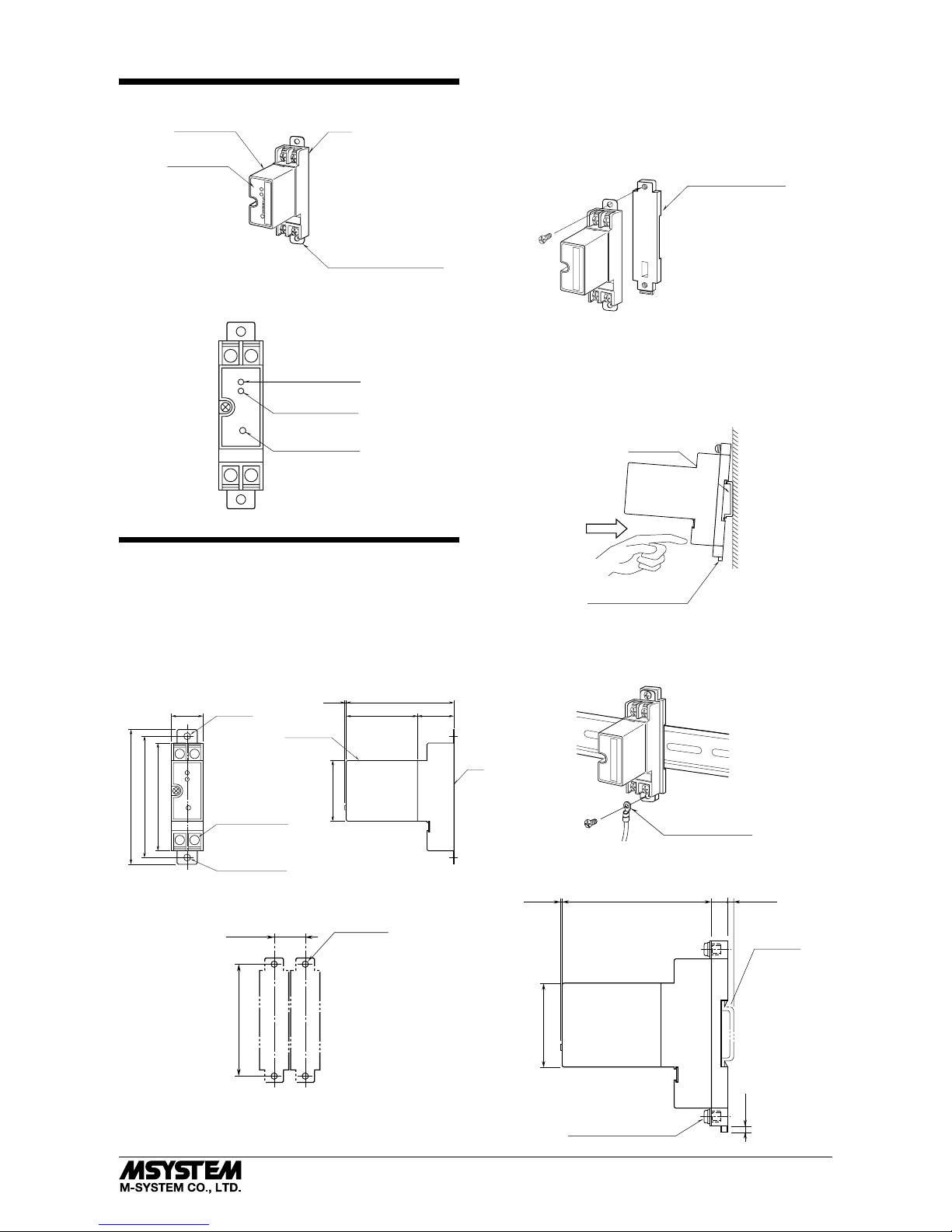
COMPONENT IDENTIFICATION
M·RESTER
MADE IN JAPAN
SER.NO
BAT
ALM
MODEL
Ground Terminal (G)
(used as mounting bracket)
Head Element
Base
Specifications
Head Element is secured to Base
with screw when the surge protector
is shipped from Factory.
■ FRONT PANEL CONFIGURATION
P–P+
S
–
S+
BAT Indicator LED
ALM Indicator LED
CHK Check Button
INSTALLATION
In order to separate the head element from the base, loosen
the screw located at the left-center of the element.
■ WALL MOUNTING
Refer to the drawings below.
• EXTERNAL DIMENSIONS unit: mm (inch)
P–P+
S–S+
23.5 (.93)
80 (3.15)
2–5 (.20) dia.
MTG HOLE
90 (3.54)
100 (3.94)
4–M4 TERMINAL SCREW
GROUND TERMINAL (G)
(used as mounting bracket)
27 (1.06)53 (2.09)
80 (3.15)
45 (1.77)
HEAD ELEMENT
BASE
1 (.04)
• MOUNTING REQUIREMENTS unit: mm (inch)
25 (.97) min.
2–M4 SCREW
90 (3.54)
■ DIN RAIL MOUNTING (Only for /A33)
1. MOUNTING ONTO THE ADAPTOR
Before DIN rail mounting, secure the mounting bracket of
MDP to the mounting adaptor with a screw provided with
this product. In this step, secure at one point.
DIN Rail Mounting Adaptor
M•RESTER
2. DIN RAIL MOUNTING
Set the base socket so that its mounting slider is at the bottom. Position the upper hook at the rear side of base socket
on the DIN rail and push in the lower. When removing the
socket, push down the mounting slider utilizing a minus
screwdriver and pull.
DIN Rail Mounting Slider
35 mm wide
DIN Rail
3. GROUNDING
Secure the mounting bracket at the other point with the
other screw. In this step, secure the grounding wire together with the screw.
M•RESTER
Solderless Ter
minal
• MOUNTING REQUIREMENTS unit: mm (inch)
80 (3.15)
45 (1.77)
8.5
(.33)
1 (.04)
[3.3 (.13)]
DIN RAIL
35mm wide
4
(.18)
2–M4 MOUNTING SCREW
(used as ground terminal (G))
Page 3

MDPA-24 / MDPA-65
5-2-55, Minamitsumori, Nishinari-ku, Osaka 557-0063 JAPAN
Phone: +81(6)6659-8201 Fax: +81(6)6659-8510 E-mail: info@m-system.co.jp
EM-8258 Rev.2 P. 3 / 3
TERMINAL CONNECTION
Connect the unit as in the diagram below.
Be sure to cross-wire between the Ground terminal (G) and
that of the protected equipment. When the surge protector is connected with a device which has no ground terminal such like M-System’s (See figure below), ground the
M-RESTER Ground terminal (G) only.
M-RESTER
IN
M-RESTER
CURRENT LOOP SUPPLY
CENTRAL
STATION
FIELD
(PROTECTED
EQUIPMENT)
FROM
FIELD
TO
CENTRAL
STATION
+
–
P–P+S–
S+
P–P+S–
S+
CABLE
G
G
+
–
G
■ GROUNDING
M-RESTER
PROTECTED
EQUIPMENT
G
G
CROSSOVER WIRE
GROUNDING
(100 ohms or less)
A crossover wire between M-RESTER ground and the ground or
metallic housing of the equipment is required for protection.
If the protected equipment has no ground terminal, ground the
M-RESTER only.
When the M-RESTER is mounted with DIN Rail Mounting Adapter,
connect the grounding wire to the mounting screw of the M-RESTER.
WIRING INSTRUCTIONS
■ SCREW TERMINAL
Torque: 0.8 N·m
MAINTENANCE
■ WIRING
1) Make sure that wiring is done as instructed in the connection diagram.
2) Make sure that the Ground terminal (G) is connected to
the metallic housing of protected equipment.
3) Make sure that the Ground terminal (G) is grounded to
earth.
■ HEAD ELEMENT MODULE
Check surge protectors periodically. Many cases of lightning are ignored, and even lightning at a far distance often
causes inductive surges.
We recommend that you check your surge protector about
twice a year, before and after the rainy season. Check
whenever you experience a strong lightning occurrence.
DO NOT test it during a thunder storm.
For testing, press CHK (Check) button on the front and LED
tuns on or off according to the surge protector’s condition as
shown in the table below.
• Discharge Element Status Table
Normal
: ON
*
1 : With pulsating line signal or that containing ripples, the LED may
flicker or blink when the voltage limiter is degraded.
: OFF
Normal
Discharged
Normal
Near End
End of Life
Unable to Judge
Normal
Degraded*
1
No Need
Near
BatteryALMBAT
Discharge
Element
Voltage
Limiter
Replacement
Immediately
Required
Replace the had element module to a new one immediately
when the LEDs indicate so.
 Loading...