

Page 1
MODEL: MDP-24-1
http://www.m-system.co.jp/ MDP-24-1 SPECIFICATIONS ES-8119 Rev.16 Page 1/4
Lightning Surge Protectors for Electronics Equipment M-RESTER
M•RESTER
MADE IN JAPAN N1430B
Lot.NO
MODEL
LIGHTNING SURGE PROTECTOR
FOR STANDARD SIGNAL LINE & PULSE USE
Functions & Features
• Designed specifically for 4 – 20mA DC and
pulse signal line including both 4-wire and 2-wire
transmitters
• Absorbs surges only without affecting instrumentation
signal
• No interruption of signal by unplugging surge protector
element
• CE marking
• UL approval
Application Examples
• Protects two-wire transmission lines
• Protects electronic instruments’ I/O
Weight:
120 g (0.26 lbs), standard
145 g (0.32 lbs), with DIN rail mounting adapter
PERFORMANCE
Max. continuous operating voltage (Uc):
Line to line: 30 V min
Line to earth: ±300 V min
Voltage protection level (Up):
• @ 1 kV (100 A)
Line to line: 40 V max.
Line to earth: ±650 V max.
• @ 2 kV (1 kA)
Line to line: 45 V max.
Line to earth: ±800 V max.
Response time:
Line to line: ≤ 4 nsec.
Line to earth: ≤ 20 nsec.
Leakage current:
Line to line: ≤ 5 μA @ 30 V DC
Line to earth: ≤ 5 μA @ ±140 V DC
Max. discharge current (Imax): 5000 A (8 / 20 μs)
Nominal current (IN): 100 mA
Internal series resistance: 20 Ω ±10 % (including return)
Capacitance @ 1 MHz:
Line to line: ≤ 1000 pF
Line to earth: ≤ 100 pF
MODEL: MDP–24–1[1]
ORDERING INFORMATION
• Code number: MDP-24-1[1]
Specify a code from below for [1].
(e.g. MDP-24-1/A33)
[1] OPTIONS
DIN rail mounting adapter
blank: Without
/A33: With adapter (model: A-33) (UL unavailable)
GENERAL SPECIFICATIONS
Construction: Plug-in
Connection: M4 screw terminals (torque 0.8 N·m)
Screw terminal: Nickel-plated steel
Housing material: Flame-resistant resin (black)
INSTALLATION
Operating temperature: -5 to +55°C (23 to 131°F)
Operating humidity: 30 to 90 %RH (non-condensing)
Mounting: Surface or DIN rail
STANDARDS & APPROVALS
CE conformity:
EMC Directive (2004/108/EC)
EMI EN 61000-6-4
EMS EN 61000-6-2
Approval:
Protectors for Data Communications and Fire
Alarm Circuits (UL 497B)
Surge protection: IEC 61643-21 (Categories C1, C2)
Page 2
MODEL: MDP-24-1
http://www.m-system.co.jp/ MDP-24-1 SPECIFICATIONS ES-8119 Rev.16 Page 2/4
CONNECTION EXAMPLES
M-RESTER
IN
M-RESTER
CURRENT LOOP SUPPLY
(protected device)
2-WIRE TRANSMITTER
(protected device)
CENTRAL
STATION
FIELD
G
FROM
FIELD
TO
CENTRAL
STATION
+
–
P–P+S–
S+
P–P+S–
S+
CABLE
GG
G
+
–
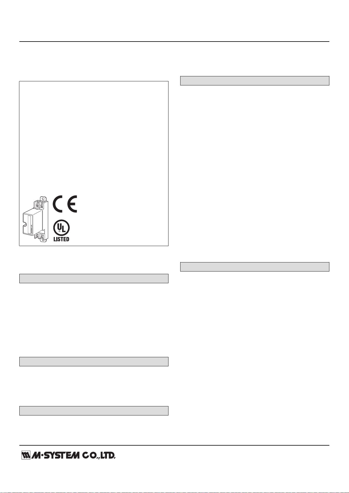
■ PROTECTING TWO-WIRE SIGNAL LINES ■ PROTECTING ELECTRONIC INSTRUMENTS’ I/O
P+
G
P–
S+
S–
+
–+–
U
V
G
Receiver
(protected device)
+
–
+
–
U
V
G
Transmitter
(protected device)
M-RESTER
S+
G
S–
P+
P–
M-RESTER
Signal
Line
*1
*2 *2
*1. Install a circuit protector when the transmitter output current exceeds 100mA.
*2. The M-RESTER is designed in particular to protect signal lines.
To protect power supply lines, install other types of surge protectors.
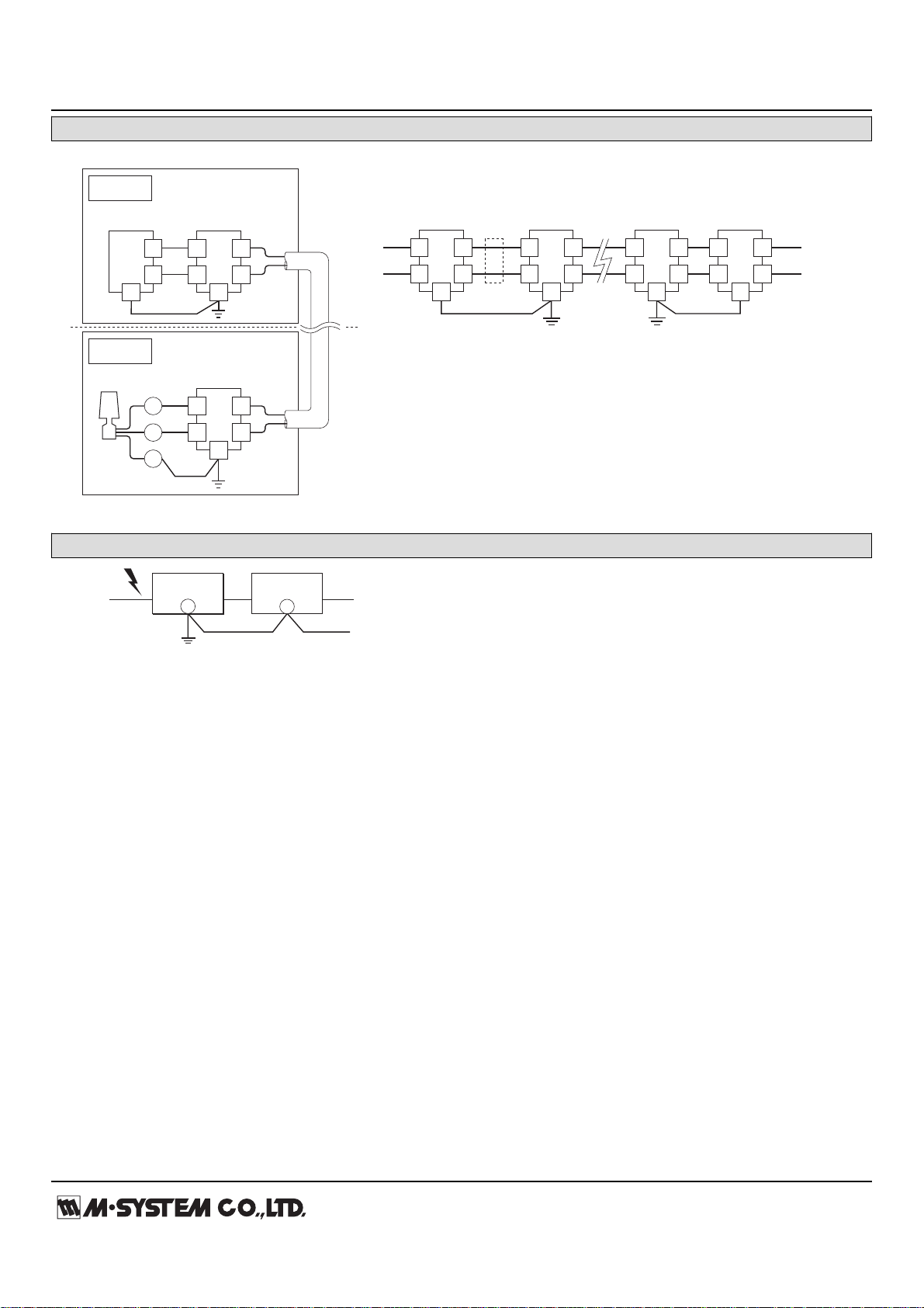
M-RESTER
PROTECTED
EQUIPMENT
G
G
CROSSOVER WIRE
GROUNDING
(100 ohms or less)
A crossover wire between M-RESTER ground and the ground or
metallic housing of the equipment is required for protection.
If the protected equipment has no ground terminal, ground the
M-RESTER only.
When the M-RESTER is mounted with DIN Rail Mounting Adapter,
connect the grounding wire to the mounting screw of the M-RESTER.
GROUNDING
Page 3

MODEL: MDP-24-1
http://www.m-system.co.jp/ MDP-24-1 SPECIFICATIONS ES-8119 Rev.16 Page 3/4
EXTERNAL DIMENSIONS & TERMINAL ASSIGNMENTS unit: mm (inch)
27 (1.06)53 (2.09)
80 (3.15)
P–P+
S
–
S+
23.5 (.93)
80 (3.15)
90 (3.54)
100 (3.94)
4–M4 TERMINAL SCREW
DIN RAIL
35mm wide
45 (1.77)
4 (.16)
8.5
(.33)
[3.3 (.13)]
2–M4 MOUNTING SCREW
(used as ground terminal (G))
■ STANDARD
■ WITH DIN RAIL MOUNTING ADAPTER
P–P+
S–S+
23.5 (.93)
80 (3.15)
2–5 (.20) dia.
MTG HOLE
90 (3.54)
100 (3.94)
4–M4 TERMINAL SCREW
GROUND TERMINAL (G)
(used as mounting bracket)
27 (1.06)53 (2.09)
80 (3.15)
45 (1.77)
HEAD ELEMENT
BASE
25 (.97) MIN.
2–M4 SCREW
90 (3.54)
MOUNTING REQUIREMENTS unit: mm (inch)
Page 4

MODEL: MDP-24-1
http://www.m-system.co.jp/ MDP-24-1 SPECIFICATIONS ES-8119 Rev.16 Page 4/4
SCHEMATIC CIRCUITRY & CONNECTION DIAGRAM
BASE
+
SURGE
SIDE
S
+
–
P
P
S
G
–
PROTECT
SIDE
Discharge
Elements
20Ω
ELEMENT
ZD
GROUND TERMINAL
(used as mounting attachment)
*
*The zenor diode has polarity.
Zero-cross signal cannot be connected.
Specifications are subject to change without notice.
 Loading...