

Page 1
MODEL: MDP-100
http://www.m-system.co.jp/ MDP-100 SPECIFICATIONS ES-8121 Rev.12 Page 1/4
Lightning Surge Protectors for Electronics Equipment M-RESTER
M•RESTER
MADE IN JAPAN N1430B
Lot.NO
MODEL
LIGHTNING SURGE PROTECTOR FOR AC/DC POWER SUPPLY USE (1A)
Functions & Features
• Designed for AC and specifically for DC power supplies up
to 1 A
• Beneficial for protecting instruments from
counter electromotive force by inductors and of course
normal lightning surges entering from power supply lines
• 1 A fuse incorporated in element circuit
MODEL: MDP–100[1]
PERFORMANCE
Max. line voltage (Uc): 120 V AC, 170 V DC
Discharge voltage:
Line to line: ≥ 190 V
Line to earth: ≥ 410 V
Voltage protection level (Up):
Line to line: 400 V max.
Line to earth: 800 V max.
Response time: ≤ 0.1 μsec.
Leakage current:
Line to line: ≤ 0.1 mA @ 150 V DC
Line to earth: ≤ 0.1 mA @ 300 V DC
Max. discharge current (Imax): 1000 A (8/ 20 μsec.)
Nominal current (IN): 1.0 A
Dielectric strength of the base module:
1500 V AC @ 1 minute (G terminal to other terminals)
Internal series resistance: ≤ 0.4 Ω (including return)
STANDARDS & APPROVALS
Surge protection: IEC 61643-1 Class III
ORDERING INFORMATION
• Code number: MDP-100[1]
Specify a code from below for [1].
(e.g. MDP-100/A33)
[1] OPTIONS
DIN rail mounting adapter
blank: Without
/A33: With adapter (model A-33)
GENERAL SPECIFICATIONS
Construction: Plug-in
Surge protection type: Voltage limiting type one-port SPD
Connection: M4 screw terminals (torque 0.8 N·m)
Screw terminal: Nickel-plated steel
Housing material: Flame-resistant resin (black)
INSTALLATION
Operating temperature: -5 to +60°C (23 to 140°F)
Operating humidity: 30 to 90 %RH (non-condensing)
Mounting: Surface or DIN rail
Weight:
90 g (0.20 lbs), standard
115 g (0.25 lbs), with DIN rail mounting adapter
Page 2
MODEL: MDP-100
http://www.m-system.co.jp/ MDP-100 SPECIFICATIONS ES-8121 Rev.12 Page 2/4
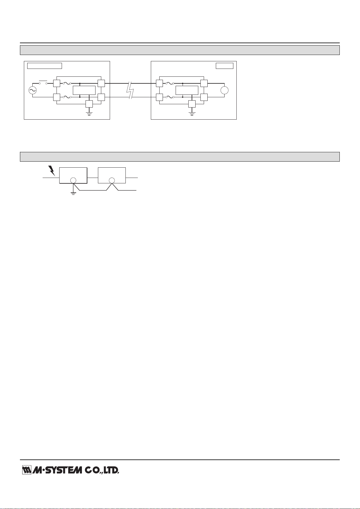
CONNECTION EXAMPLES
P1
P2
S1
S2
M-RESTER
Relay,
Coil, etc.
G
Discharge
Element
1A
P1
P2
S1
S2
M-RESTER
G
Discharge
Element
1A
R
CONTROL ROOM
FIELD
The M-RESTER must be connected with its terminals S1 and S2 faced on power source side
in order that the fuses would be blown in case of shortcircuit of the discharge element.
M-RESTER
PROTECTED
EQUIPMENT
G
G
CROSSOVER WIRE
GROUNDING
(100 ohms or less)
A crossover wire between M-RESTER ground and the ground or
metallic housing of the equipment is required for protection.
If the protected equipment has no ground terminal, ground the
M-RESTER only.
When the M-RESTER is mounted with DIN Rail Mounting Adapter,
connect the grounding wire to the mounting screw of the M-RESTER.
GROUNDING
Page 3

MODEL: MDP-100
http://www.m-system.co.jp/ MDP-100 SPECIFICATIONS ES-8121 Rev.12 Page 3/4
EXTERNAL DIMENSIONS & TERMINAL ASSIGNMENTS unit: mm (inch)
P2P1
S2S1
23.5 (.93)
80 (3.15)
2–5 (.20) dia.
MTG HOLE
90 (3.54)
100 (3.94)
4–M4 TERMINAL SCREW
GROUND TERMINAL (G)
(used as mounting bracket)
27 (1.06)53 (2.09)
80 (3.15)
45 (1.77)
HEAD ELEMENT
BASE
27 (1.06)53 (2.09)
80 (3.15)
P2P1
S2S1
23.5 (.93)
80 (3.15)
90 (3.54)
100 (3.94)
45 (1.77)
4 (.16)
8.5
(.33)
[3.3 (.13)]
DIN RAIL
35mm wide
4–M4 TERMINAL SCREW
2–M4 MOUNTING SCREW
(used as ground terminal (G))
■ STANDARD
■ WITH DIN RAIL MOUNTING ADAPTER
25 (.97) MIN.
2–M4 SCREW
90 (3.54)
MOUNTING REQUIREMENTS unit: mm (inch)
Page 4

MODEL: MDP-100
http://www.m-system.co.jp/ MDP-100 SPECIFICATIONS ES-8121 Rev.12 Page 4/4
SCHEMATIC CIRCUITRY & CONNECTION DIAGRAM
BASE
POWER
SUPPLY
S1 P1
P2
S2
G
TO EQUIPMENT
Discharge
Elements
ELEMENT
GROUND TERMINAL
(used as mounting attachment)
1A
1A
Note: When the head element is removed, the line will be open.
Specifications are subject to change without notice.
 Loading...