

Page 1
MODEL: MD7ST
http://www.m-system.co.jp/ MD7ST SPECIFICATIONS ES-8057 Rev.6 Page 1/6
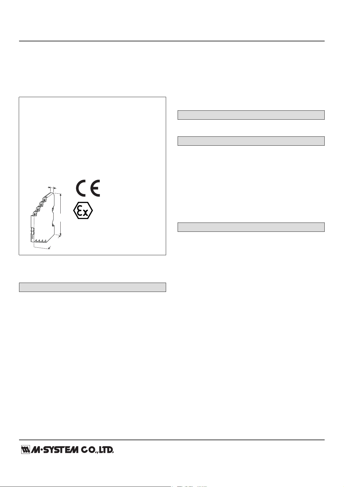
Lightning Surge Protectors for
7 (.28)
95
(3.74)
98
(3.86)
mm (inch)
Electronics Equipment M-RESTER
LIGHTNING SURGE PROTECTOR FOR STANDARD SIGNAL LINE
(ultra-slim)
Functions & Features
• High discharge current capacity 20 kA (8 / 20μs), 1 kA (10
/ 350 μs)
• Ultra-thin 7-mm-wide module can be mounted
in high density
• Excellent protection employing multi-stage SPD circuits
• DIN rail mounting and grounding
• Shield terminal provided
• CE marking
[3] LOOP DISCONNECT FUSE
0: Without
1: With (CENELEC/ATEX approval Not selectable)
[4] SAFETY APPROVAL
0: None
2: CENELEC intrinsic safety (ATEX)
RELATED PRODUCTS
• Loop disconnect fuse (model: MD7F)
GENERAL SPECIFICATIONS
Construction: Slim-sized front terminal structure
Degree of protection: IP20
Connection: Euro terminal block (torque 0.3 N·m)
Applicable wire size: 0.2 – 2.5 mm
Grounding: DIN Rail
Housing material: Flame-resistant resin (black)
Loop disconnect fuse: Current rating 250 mA
(Separates the protected device from the power source
when the former fails in the shortcircuit mode.)
2
MODEL: MD7ST–[1][2][3][4]
ORDERING INFORMATION
• Code number: MD7ST-[1][2][3][4]
Specify a code from below for each [1] through [4].
(e.g. MD7ST-24FF00)
For the safety approval code 2, specify the product’s
destination country using Ordering Information Sheet (No.
ESU-8057).
[1] NOMINAL VOLTAGE
24: 24 V DC
60: 60 V DC
[2] SHIELD TERMINAL (line / earth)
FF: Floating / Floating
FG: Floating / Grounding
GF: Grounding / Floating
GG: Grounding / Grounding
INSTALLATION
Operating temperature: -25 to +85°C (-13 to +185°F)
(See Safety Parameters for use in a hazardous location.)
Operating humidity: 30 to 90 %RH (non-condensing)
Mounting: DIN Rail (TH35-7.5, 1-mm-thick)
Oxide film on the surface of an aluminium rail may lower
the electric conductivity between this module and the
ground. Use a steel or copper rail.
Weight: 70 g (2.5 oz)
Page 2
MODEL: MD7ST
http://www.m-system.co.jp/ MD7ST SPECIFICATIONS ES-8057 Rev.6 Page 2/6
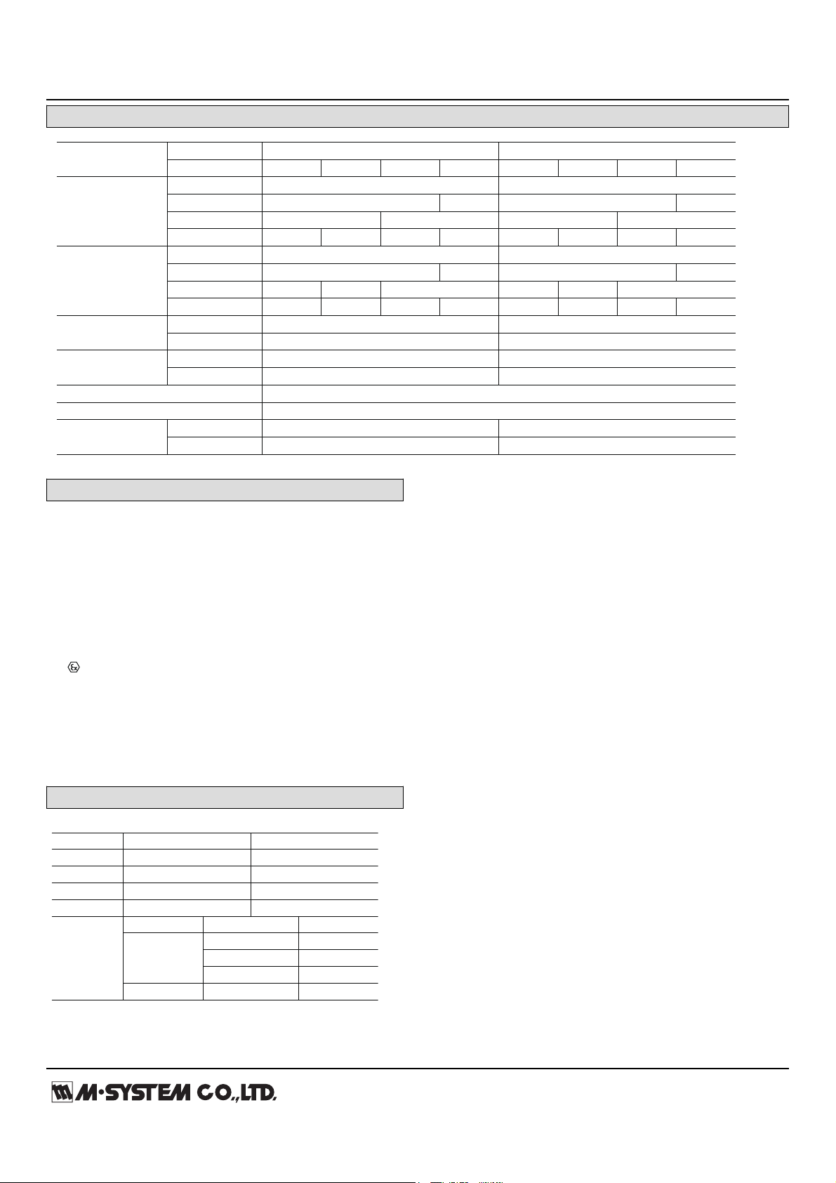
PERFORMANCE
MODEL NO.
NOMINAL VOLTAGE
MD7ST-24 MD7ST-60
SHLD TERMINAL
FF FG GF GG FF FG GF GG
Max. continuous Line to Line 30V 70V
operating voltage
Line to Earth ±160V 30V ±160V 70V
(Uc)
Line to SHLD ±160V 30V ±160V 70V
SHLD to Earth ±160V short ±160V short ±160V short ±160V short
Voltage protection Line to Line 60V 115V
level (Up)
Line to Earth ±800V
±60V
±800V
±115V
@4kV (1.2 / 50 µs)
Line to SHLD
±1200V
±800V
±60V
±1200V
±800V
±115V
SHLD to Earth
±800V
short
±800V
short
±800V
short
±800V
short
Leakage current Line to Line ≤5µA ≤5µA
@Uc
Other sections ≤5µA ≤5µA
Response time Line to Line ≤4 nsec. ≤4 nsec.
Other sections ≤20 nsec. ≤20 nsec.
Max. discharge current (Imax) 20kA (8 / 20 µs), 1.0kA (10 / 350 µs)
Nominal current (I
N) 250mA
Internal series Without fuse 4.7Ω ±10% per line 10Ω ±10% per line
resistance
With fuse 7.5Ω ±10% per line 12.5Ω ±10% per line
CENELEC: Intrinsic safety (ATEX)
II 1G, Ex ia IIC; T4 and T5
EN 60079-0: 2006
EN 60079-11: 2007
EN 60079-26: 2007
■ CENELEC / ATEX IS DATA
MD7ST-24 MD7ST-60
Ui (Vmax)
32V 60V
Ii (Imax)
any any
Ci
10 nF 5 nF
Li
0 µH 0 µH
Pi
Temp. Class Range Parameter
T4
-25 to +40°C 1.3W
-25 to +60°C 1.2W
-25 to +80°C 1.0W
T5 -25 to +40°C 1.0W
STANDARDS & APPROVALS
CE conformity:
ATEX Directive (94/9/EC)
Ex ia EN 60079-11: 2007
Category 1G EN 60079-26: 2007
EMC Directive (2004/108/EC)
EMI EN 61000-6-4: 2007
EMS EN 61000-6-2: 2005
Safety approval:
Surge protection: IEC 61643-21: 2000
(Categories C1, C2, D1)
SAFETY PARAMETERS
Page 3

MODEL: MD7ST
http://www.m-system.co.jp/ MD7ST SPECIFICATIONS ES-8057 Rev.6 Page 3/6
DESCRIPTIONS
With Shield
Cable
Shield
Not Grounded
Shield to Signal
Isolated
Shield to Signal
Not Isolated
FF
Shield
Grounded
FG
Shield
Not Grounded
GF
Shield
Grounded
GG
Without Shield
Signal to Earth
Isolated
Signal to Earth
Not Isolated
FF
GG
• The surge protector has a dedicated shield terminal effective for easy shield wiring and surge protection.
• Review the shield method (grounding, non-grounding, connecting to SG, etc.) required by the protected device or system.
• There is no electrical effect to the shield by installing the surge protector, but an appropriate shield terminal type must be
selected to suit user applications.
• Refer to the flow chart below to choose.
■ SELECTING SHIELD TERMINAL TYPE
MD7ST
5
–
+
2
7
8
4 1
(SHLD)
DIN RAIL
DIN RAIL
ADAPTOR
Fuse/Disconnect
DC Power Supply
4 – 20mA
Transmitter
Field-mount
Surge Protector
(model: MD6x)
+
–
250Ω
Power Bus
To other 4 – 20mA loops
+
–
• Specify ‘Loop disconnect fuse’ type when multiple transmitters are connected to single power bus.
• Loop disconnect fuse is used to separate a transmitter loop from the power bus when it fails in the shortcircuit mode.
SELECTING LOOP DISCONNECT FUSE■
Page 4

MODEL: MD7ST
http://www.m-system.co.jp/ MD7ST SPECIFICATIONS ES-8057 Rev.6 Page 4/6
CONNECTION EXAMPLES
5 2
8
4 1
(SHLD)
DIN RAIL
DIN RAIL
ADAPTOR
Current Loop Supply
4 – 20mA
Transmitter
Field-mount
Surge Protector
(model: MD6x)
+
–
+
–
FG
Protected Side
Crossover Wire
Surge Side
*1. Oxide film on the surface of an aluminium rail may lower the electric conductivity between this module and the ground.
Use a steel or copper rail.
*2. Be sure to ground the DIN rail. Recommended grounding resistance ≤100Ω
*3. Cross-wire between the DIN rail and the metal housing of the protected device to equalize the earth potential.
Ground only the surge protector when the protected device has no ground terminal.
*4. Shield wiring method is an example. Proceed according to the system requirements.
*4
*2
*1
*3
8
6
5
4
1
2
3
7
4
1
5
2
6
3
8
7
95 (3.74)
7
(.28)
98 (3.86)
[1.5 (.05)]
8–M3 EURO
TERMINAL
DIN RAIL
(35 mm wide)
DIN RAIL
ADAPTOR
WIRE INSERTION ANGLE: approx. 20°
57 (2.24)
1.9 (.07)
LOOP DISCONNECT
FUSE (option)
EXTERNAL DIMENSIONS & TERMINAL ASSIGNMENTS unit: mm (inch)
Page 5

MODEL: MD7ST
http://www.m-system.co.jp/ MD7ST SPECIFICATIONS ES-8057 Rev.6 Page 5/6
SCHEMATIC CIRCUITRY
SHIELD TERMINAL
MODEL NO. SCHEMATIC CIRCUITRY APPLICATIONS
5
–
+
+
2
6 3
7
8
DISCHARGE
ELEMENT
DISCHARGE
ELEMENT
4 1
Series Resistance
(SHLD)
Surge Side Protected Side
Fuse/Disconnect
DIN RAIL ADAPTOR
(for grounding)
DIN RAIL
Grounding
• Line to SHLD:
Floating
• Earth to SHLD:
Floating
• MD7ST-xFF0x
(No fuse option)
• MD7ST-xFF1x
(Fuse option)
• Standard type
• To protect a device having
isolation between Signal
and Earth.
• When SHLD should be
floating against the earth.
(single-end grounding)
• Line to SHLD:
Floating
• Earth to SHLD:
Grounding
• MD7ST-xFG0x
(No fuse option)
• MD7ST-xFG1x
(Fuse option)
• To protect a device having
isolation between Signal
and Earth.
• When SHLD should be
grounded. (single- or both end grounding)
• Line to SHLD:
Grounding
• Earth to SHLD:
Floating
• MD7ST-xGF0x
(No fuse option)
• MD7ST-xGF1x
(Fuse option)
• To protect a device having
isolation between Signal
and Earth.
• When SHLD wire should be
connected to SG terminal
of the protected device.
(SHLD is not grounded to
the earth.)
• Line to SHLD:
Grounding
• Earth to SHLD:
Grounding
Sections enclosed with broken line may differ depending upon the models; without Fuse/Disconnect option, fuse circuit is shorted.
• MD7ST-xGG0x
(No fuse option)
• MD7ST-xGG1x
(Fuse option)
• To protect a device which
does not have a good
dielectric strength between
Signal and Earth.
5
–
+
–
+
2
6 3
7
8
DISCHARGE
ELEMENT
4 1
Series Resistance
(SHLD)
Surge Side Protected Side
DIN RAIL ADAPTOR
(for grounding)
DIN RAIL
Grounding
Fuse/Disconnect
5
–
+
–
+
2
6 3
7
8
DISCHARGE
ELEMENT
DISCHARGE
ELEMENT
4 1
Series Resistance
(SHLD)
Surge Side Protected Side
DIN RAIL ADAPTOR
(for grounding)
DIN RAIL
Grounding
Fuse/Disconnect
5
–
+
–
+
2
6 3
7
8
DISCHARGE
ELEMENT
4 1
Series Resistance
(SHLD)
Surge Side Protected Side
Fuse/Disconnect
DIN RAIL ADAPTOR
(for grounding)
DIN RAIL
Grounding
Page 6

MODEL: MD7ST
http://www.m-system.co.jp/ MD7ST SPECIFICATIONS ES-8057 Rev.6 Page 6/6
Specifications are subject to change without notice.
 Loading...