

Page 1
MODEL: MD6N-24
http://www.m-system.co.jp/ MD6N-24 SPECIFICATIONS ES-8284 Rev.5 Page 1/3
Lightning Surge Protectors for
■
SELECTABLE WIRING CONDUITS SPECIFIC TO EACH APPROVAL
‘N’ marked combinations are not selectable.
APPROVAL
0 1 2 3 4 5
WIRING CONDUIT
0 Y Y Y N N Y
1 Y Y Y Y Y Y
2 Y Y Y N Y Y
Electronics Equipment M-RESTER
5: FM nonincendive
Confirm selectable combinations of approval and wiring
conduit types in the table.
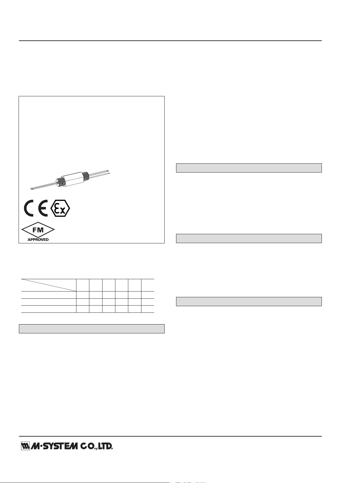
LIGHTNING SURGE PROTECTOR FOR STANDARD SIGNAL LINE & PULSE USE
(conduit mount, weather-proof, 24 V DC line voltage)
Functions & Features
• Designed specifically for 4 – 20 mA DC and
pulse signal line including both 4-wire and 2-wire
transmitters
• Direct mount in a wiring conduit of outdoor enclosures
• Absorbs surges only without affecting instrumentation
signal
• CE marking (conforms to ATEX and EMC)
MODEL: MD6N–24–[1][2][3]
[2] WIRING CONDUIT
0: G 1/2
1: 1/2 NPT
2: M20 × 1.5
Confirm selectable combinations of approval and wiring
conduit types in the table.
[3] BODY MATERIAL
B: Brass
S: Stainless steel
GENERAL SPECIFICATIONS
Degree of protection: IP65
Wiring conduit: See ‘Ordering information.’
Electrical connection: Leadwires
Leadwire diameters
Cable side & grounding: AWG20
Protected equipment side: AWG22
Body material: Nickel-plated brass or stainless steel 316
INSTALLATION
Operating temperature: -40 to +85°C (-40 to +185°F)
(See Safety Parameters for use in a hazardous
location.)
Mounting: Screwed into an electrical conduit of outdoor
enclosures
Weight: 330 g (0.73 lbs)
PERFORMANCE
Discharge voltage (peak voltage)
Line to line: 30 V min.
ORDERING INFORMATION
• Code number: MD6N–24–[1][2][3]
Specify a code from below for [1] through [3]
(e.g. MD6N-24-00B)
For the safety approval codes 2 and 4, specify the product’s
destination country using Ordering Information Sheet (No.
ESU-8284).
[1] SAFETY APPROVAL
0: None
1: FM intrinsically safe
2: CENELEC intrinsic safety (ATEX)
3: FM explosion-proof
4: CENELEC flameproof (ATEX)
Line to ground: ±160 V min.
Max. surge voltage
Line to line: 40 V max.
Line to ground: ±650 V max.
(The maximum voltage that could pass through the surge
protector. Protected equipment must be able to withstand
this voltage for a very short time period.)
Response time:
Line to line: ≤ 4 nsec.
Line to ground: ≤ 20 nsec.
Leakage current:
Line to line: ≤ 5 μA @ 30 V DC
Line to ground: ≤ 5 μA @ ±160 V DC
Discharge current capacity: 10000 A (8/ 20 μsec.)
Max. load current: 100 mA
Page 2
MODEL: MD6N-24
http://www.m-system.co.jp/ MD6N-24 SPECIFICATIONS ES-8284 Rev.5 Page 2/3
Internal series resistance: Approx. 22 Ω including return
CENELEC: Intrinsic safety (ATEX)
II 1G, EEx ia IIC; T5 and T6
(EN 50020: 2002, EN 50284: 1999)
CENELEC: Flameproof (ATEX)
II 2G, Ex d IIC; T5 and T6
(EN 60079-1: 2004)
Max. line voltage
Without safety approval: 30 V DC
With safety approval: 28 V DC
Capacitance @ 1 kHz:
Line to line: ≤ 2500 pF
Line to ground: ≤ 100 pF
STANDARDS & APPROVALS
CE conformity:
ATEX Directive (94/9/EC)
EEx ia EN 50020: 2002
Category 1G EN 50284: 1999
Ex d EN 60079-1: 2004
EMC Directive (2004/108/EC)
EMI EN 61000-6-4: 2007
EMS EN 61000-6-2: 2005
Safety approval:
FM: Intrinsically safe
Class I, Div. 1, Groups A, B, C and D
Class II, Div. 1, Groups E, F and G
Class III, Div. 1
Class I, Zone 0, AEx ia IIC
T5 and T6
(Class 3610: 2010, ANSI/ISA 60079-11: 2009)
FM: Explosion-proof and Dust-ignition proof
Class I, Div. 1, Groups A, B, C and D
Class II, Div. 1, Groups E, F and G
Class III, Div. 1
T6
(Class 3615: 2006)
FM: Nonincendive
Class I, Div. 2, Groups A, B, C, and D
Class II, Div. 2, Groups E, F and G
Class III, Div. 1
T6
(Class 3611: 2004)
(ATEX))
Ii (Imax) 100 mA ('Any' for CENELEC intrinsic safety
approval (ATEX))
Pi 750 mW
Ci 2.5 nF
Li 0 mH
SAFETY PARAMETERS
Operating temperature:
T5 -40 to +80°C
T6 -40 to +70°C
-40 to +75°C for CENELEC (ATEX) flameproof
-40 to +80°C for FM explosion-proof and nonincendive
Ex-data:
Ui (Vmax) 30 V ('Any' for CENELEC intrinsic safety approval
Page 3

MODEL: MD6N-24
http://www.m-system.co.jp/ MD6N-24 SPECIFICATIONS ES-8284 Rev.5 Page 3/3
CONNECTION EXAMPLES
Conduit Mount
Type SPD
–
+
red
black
S
S
To Central Station
Cable
–
+
IN
Current Loop Supply
Central Station
(Protected Equiment)
From Field
+
–
P–
P+
S–
S+
G
MDP-24-1
Field
G
–
+
G
S
S
yellow
blue
green
G
Protected Equipment
(Protected Equipment Enclosure)
Connect the Conduit Mount Type SPD’s green leadwire to the ground terminal inside the protected equipment enclosure to
ground through the enclosure’s outside ground terminal.
If the enclosure does not have an inside ground terminal, connect the green leadwire directly to the outside ground wire
pulled inside the enclosure. Keep the ground wire as short as possible.
2–G 1/2, 1/2 NPT or M20x1.5
32 (1.26)
27 (1.06)
10 (.39)
{17 (.67)}
*
[22 (.87)]
**
10 (.39)
{17 (.67)}
*
[22 (.87)]
**
approx. 250 (9.8)52 (2.05)approx. 250 (9.8)
*
{ } for M20x1.5 with CENELEC (ATEX) flameproof approval
**
[ ] for 1/2 NPT
yellow
blue
green
+
leadwires
–
G
To Equipment
Ground
Equipment
Side
Discharge
Elements
22Ω
ZD
*
1
*1. The zenor diode has polarity. Zero-cross signal cannot be connected.
*2. Use only when the signal line requires functional grounding.
This is NOT for surge protection.
*
2
red
black
+
–
Cable
Side
Specifications are subject to change without notice.
DIMENSIONS unit: mm (inch)
SCHEMATIC CIRCUITRY & CONNECTION DIAGRAM
 Loading...