

MODEL: MATPH
http://www.m-system.co.jp/ MATPH SPECIFICATIONS ES-8160 Rev.0 Page 1/3
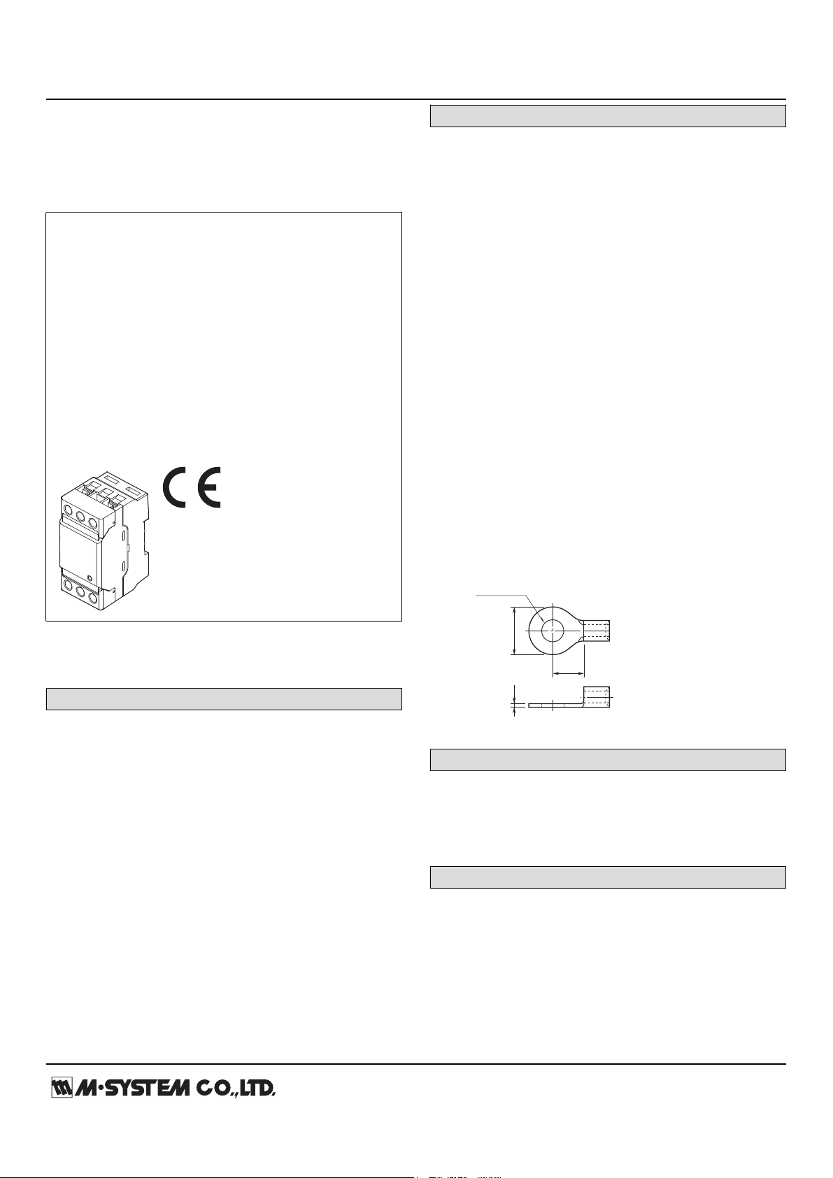
Lightning Surge Protectors for
F
d : M5 use
B ≤ 12.5 mm
F ≥ 7.0 mm
(F ≥ 8.2 mm for sharing terminals)
T ≤ 1.8 mm
• Applicable Solderless Terminal Size
diameter d
BT
Electronics Equipment M-RESTER
SURGE PROTECTOR FOR PHOTOVOLTAIC SYSTEM
(750V DC,1000V DC USE)
Functions & Features
• Surge protection for photovoltaic array and power
conditioner.
• High discharge current capacity 20 kA
• Degraded head element is automatically separated from
the power lines by the incorporated thermal breaker, and
the LED lamp (turns off) and the relay contact alerts the
failure status.
• Breakdown of the surge protector remotely detected with
the alarm output
• Photovoltaic system's resistance to earth is measurable
without removing the SPD due to spark gap employed
between line and earth.
GENERAL SPECIFICATIONS
Construction: Standalone; terminal access at the front
Degree of protection: IP20 (If the solderless terminals are
covered with insulation tubes.)
Surge protection type: One-port combination type SPD
Connection
Line: M5 screw terminal (torque: 2.5 N·m)
Alarm output: Tension clamp
Applicable wire size
Line: See the drawing below.
Alarm output: 0.13 to 1.5 mm2 (8 mm exposed)
Screw terminal
Line: Nickel-plated steel
Alarm output: Tin-plated copper alloy
Housing material: Flame-resistant resin (black)
Alarm output: Trips when the thermal breaker operates.
(N.C. contact)
Rated load:
250 V AC @50 mA (resistive load)
24 V DC @50 mA (resistive load)
Safety function: Thermal breaker incorporated
Monitor LED: Green LED turns on during normal conditions
(100 V DC to operational votage), and turns off during
failure condition, power off and the thermal breaker
operating.
MODEL: MATPH–[1]M[2]
ORDERING INFORMATION
• Code number: MATPH-[1]M[2]
Specify a code from below for each [1] and [2].
(e.g.MATPH-1000MA)
[1] OPERATIONAL VOLTAGE
750: 750 V DC
1000: 1000 V DC
MAXIMUM DISCHARGE CURRENT
M: 20kA (8/20 μsec.)
[2] ALARM OUTPUT
A: With
Y: Without
INSTALLATION
Operating temperature: -25 to +80°C (-13 to +176°F)
Operating humidity: 30 to 90 %RH (non-condensing)
Mounting: DIN Rail
Weight: 200 g (0.44 lb)
PERFORMANCE
Max. continuous operating voltage (Uc, Line to line):
750 V DC for MATPH-750
1000 V DC for MATPH-1000
Discharge voltage (Line to earth): 500 V DC
Voltage protection level (Up):
• MATPH-750
Line to line: 2.5 kV (@In)
Line to earth: 1.8 kV (@In)
• MATPH-1000
MODEL: MATPH
http://www.m-system.co.jp/ MATPH SPECIFICATIONS ES-8160 Rev.0 Page 2/3
Line to line: 3.3 kV (@In)
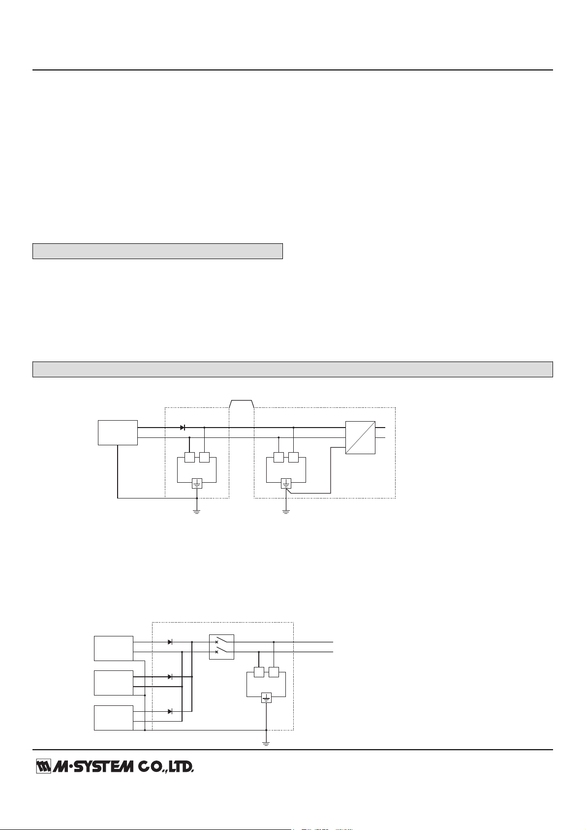
Blocking Diode
Distribution Board
Blocking Diode
10m min.
L+L−
Photovoltaic
Array
DC
AC
■ CONNECTION DIAGRAM
■ CIRCUIT BREAKER POSITION
If you want to use circuit breaker as SPD maintenance switch, insert a wiring MCCB for DC on SPD power side (diagram below).
Even when the output current of solar cell array is low, use 20 AT or more for wiring MCCB.
*2, *3
L+L−
*2, *3
*1
L+
L–
L+L−
Wiring MCCB
*1. When the wiring distance is longer than 10 m between the power conditioner and the surge protector in the switch gear, install near the power
conditioner.
*2. Cable length between the branch point and the earthing: 0.5 m or less recommended
*3. When the solar panel manufacturer requires earthing at negative line of DC side, do NOT use the earth terminal of the MATPH but use the
L- terminal. If also, earthing at positive line is necessary, earth the L+ terminal.
Solar Cell
Array
Solar Cell
Array
Solar Cell
Array
Switch Gear Common Enclosure
Switch Gear
L+
L–
L+
L–
L+
L–
Line to earth: 2.1 kV (@In)
Maximum discharge current (Imax): 20 kA (8/ 20 μs)
Nominal discharge current (In): 10 kA (8/ 20 μs)
Response time:
Line to line: ≤ 4 nsec.
Line to earth: ≤ 20 nsec.
Leakage current: ≤ 1 mA
Insulation resistance: ≥ 100 MΩ with 500 V DC (line to
alarm output)
Dielectric strength: 2000 V AC @ 1 minute (line to alarm
output)
STANDARDS & APPROVALS
Refer to the manuals to comply with the standards.
CE conformity:
Low Voltage Directive (2006/95/EC)
EN 61643-11: 2002
Surge protection:
IEC 61643-1: 1998 Class II
EN 61643-11: 2002 Class II
CONNECTION EXAMPLES

MODEL: MATPH
http://www.m-system.co.jp/ MATPH SPECIFICATIONS ES-8160 Rev.0 Page 3/3
EXTERNAL DIMENSIONS & TERMINAL ASSIGNMENTS unit: mm (inch)
50 (1.97)
15 (.59)
15 (.59)
L–
NCA1A0
L+
5–M5 SCREW
TERMINAL COVER
SPECIFICATION
ALARM OUTPUT
*
TERMINAL
*
Only for 'Alarm output' code 'A.'
MONITOR LED
[3.4 (.13)]
60 (2.36)
98 (3.86)1 (.04)
80 (3.15)
15 (.59)
12.5 (.49)
DIN RAIL
35mm wide
45°
(WIRE INSERTION ANGLE)
L
+
L
–
A1 NCA0
θ θ
θ
Monitor LED
θ
: Thermal breaker
Note: Terminals A0 & A1 are available for 'Alarm output' code 'A.'
Display
Circuit
Specifications are subject to change without notice.
SCHEMATIC CIRCUITRY
 Loading...