

Page 1
INSTRUCTION MANUAL
CT TRANSMITTER
(clamp-on current sensor)
BEFORE USE ....
Thank you for choosing M-System. Before use, please check
contents of the package you received as outlined below.
If you have any problems or questions with the product,
please contact M-System’s Sales Office or representatives.
■ PACKAGE INCLUDES:
Signal conditioner ...............................................................(1)
Sensor ..................................................................................(1)
Cable (CLSA-08, -12 only) ..................................................(1)
■ MODEL NO.
Confirm Model No. marking on the product to be exactly
what you ordered.
■ INSTRUCTION MANUAL
This manual describes necessary points of caution when
you use this product, including installation, connection and
basic maintenance procedures.
POINTS OF CAUTION
■ POWER INPUT RATING & OPERATIONAL RANGE
• Locate the power input rating marked on the product and
confirm its operational range as indicated below:
85 – 264V AC rating: 85 – 264V, 47 – 66 Hz, approx. 2 – 3VA
24V DC rating: 24V ±10%, approx. 2W
MODEL
■ AND ....
• The unit is designed to function as soon as power is supplied, however, a warm up for 10 minutes is required for
satisfying complete performance described in the data
sheet.
M5CTC
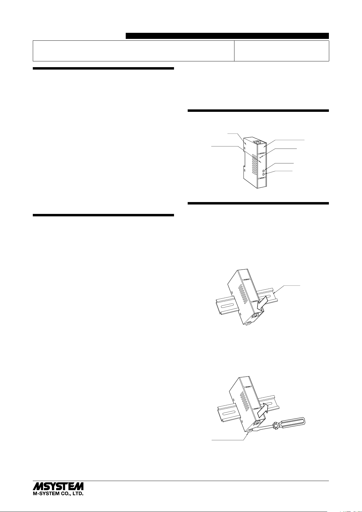
COMPONENT IDENTIFICATION
Body
Terminal Cover
Specifications
Power LED
Span Adj.
Zero Adj.
INSTALLATION
Set the unit so that its DIN rail adapter is at the bottom.
■ MOUNTING THE UNIT ON A DIN RAIL
A) Hang the upper hook at the rear side of unit on the DIN
rail.
B) Push in the lower in keeping pressing the unit to the DIN
rail.
■ GENERAL PRECAUTIONS
• Before you remove the unit or mount it, turn off the power
supply and input signal for safety.
■ ENVIRONMENT
• Indoor use.
• When heavy dust or metal particles are present in the
air, install the unit inside proper housing with sufficient
ventilation.
• Do not install the unit where it is subjected to continuous
vibration. Do not subject the unit to physical impact.
• Environmental temperature must be within -5 to +55°C
(23 to 131°F) with relative humidity within 0 to 90% RH
in order to ensure adequate life span and operation.
■ WIRING
• Do not install cables close to noise sources (relay drive
cable, high frequency line, etc.).
• Do not bind these cables together with those in which
noises are present. Do not install them in the same duct.
• Install lightning surge protectors for those wires connected to remote locations. For 24V DC power supply line,
choose a surge protector with its maximum surge voltage
40V or less between lines. Recommended M-System model: MDP-D24.
DIN Rail
A
B
■ REMOVING THE UNIT
A) Push down the DIN rail adaptor using a minus screw-
driver.
B) Pull out the lower part of the unit.
C) Remove the upper part from the DIN rail.
C
B
Spring Loaded
DIN Rail Adaptor
A
■ CLAMP-ON CURRENT SENSOR
Secure the sensor to the cable e.g. using tie wraps.
Over-voltage clamp element is incorporated for safety in
open circuit.
5-2-55, Minamitsumori, Nishinari-ku, Osaka 557-0063 JAPAN
Phone: +81(6)6659-8201 Fax: +81(6)6659-8510 E-mail: info@m-system.co.jp
EM-2486 Rev.4 P. 1 / 4
Page 2
TERMINAL CONNECTIONS
23 (.91)
29 (1.14)
Connect the unit as in the diagram below or refer to the connection diagram on the front of the unit.
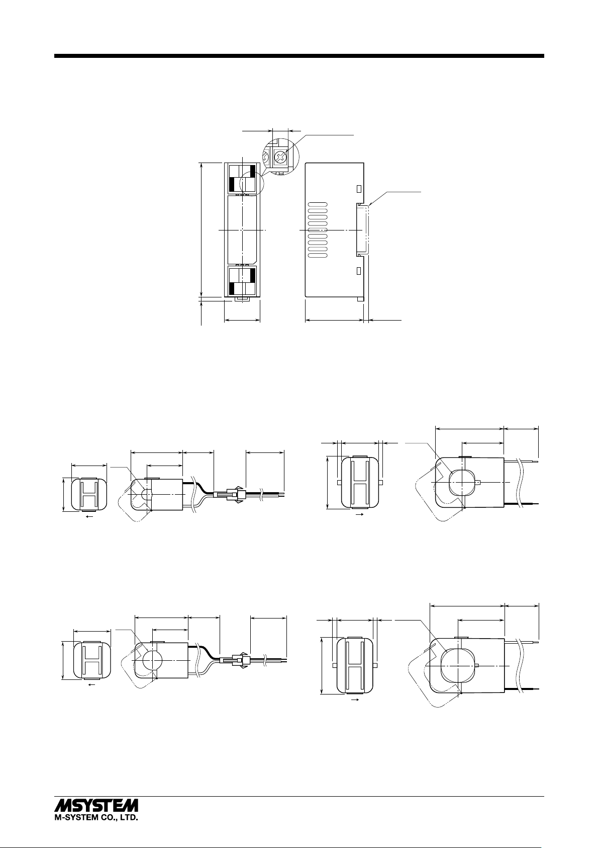
■ EXTERNAL DIMENSIONS unit: mm (inch)
M5CTC
7.3 (.29)
12
34
94 (3.70)3 (.12)
56
78
25 (.98) 41 (1.61)
• When mounting, no extra space is needed between units.
■ CLAMP-ON CURRENT SENSOR (leadwire type CLSA)
• 0 – 10A through 0 – 75A Use
Sensor model No.: CLSA-08
Sensor cable model No.: CLSA-08C-30
Applicable cable diameter: Max. 10.0
Sensor leadwire: AWG 22
Weight: 45 g (1.6 oz)
10 (.39)
dia.
41 (1.61)
27 (1.05)26 (1.02)
150 (5.91) 3000 (118)
8–M3.5 SCREW
DIN RAIL
35mm wide
[3.3 (.13)]
• 0 – 125A through 0 – 300A Use
Sensor model No.: CLSA-30
Applicable cable diameter: Max. 24.0
Sensor leadwire: AWG 18, 200 mm
Weight: 200 g (7.1 oz)
24 (.94)
4
(.16)
4
(.16)
dia.
64 (2.52)
40 (1.57)34 (1.34)
200 (7.87)
k
LK
• 0 – 100A Use
Sensor model No.: CLSA-12
Sensor cable model No.: CLSA-08C-30
Applicable cable diameter: Max. 16.0
Sensor leadwire: AWG 22
Weight: 70 g (2.5 oz)
150 (5.91)
31 (1.22)
LK
16 (.63)
dia.
44.5 (1.75)
30 (1.18)
l
47.5 (1.87)
k
KL
l
• 0 – 350A through 0 – 500A Use
Sensor model No.: CLSA-50
Applicable cable diameter: Max. 36.0
Sensor leadwire: AWG 18, 200 mm
Weight: 300 g (10.6 oz)
200 (7.87)
3000 (118)
(.16)
4
36 (1.41)
dia.
80 (3.15)
50 (1.97)38 (1.50) 4
(.16)
k
l
k
59.5 (2.34)
KL
l
5-2-55, Minamitsumori, Nishinari-ku, Osaka 557-0063 JAPAN
Phone: +81(6)6659-8201 Fax: +81(6)6659-8510 E-mail: info@m-system.co.jp
EM-2486 Rev.4 P. 2 / 4
Page 3

M5CTC
28.9 (1.14)
37.4 (1.47)
55.9 (2.20)
(detachable)
35.5
8.8
8.8
(detachable)
35.5
8.8
8.8
■ CLAMP-ON CURRENT SENSOR (screw terminal type CLSB)
Connection: M3 screw terminal
(nickel-plated steel; torque 0.5 N·m)
• 0 – 10A through 0 – 50A Use
Sensor model No.: CLSB-05
Applicable cable diameter: Max. 10.0
Weight: 45 g (1.6 oz)
(.34)
26.3 (1.04)8.6
KL
8.6
(.34)
48 (1.89)
2–M3 SCREW
10 dia. (.39)
kkl
l
TERMINAL COVER
(detachable)
• 0 – 60A through 0 – 100A Use
Sensor model No.: CLSB-10
Applicable cable diameter: Max. 16.0
Weight: 80 g (2.8 oz)
(.30)
30.5 (1.20)7.5
KL
7.5
(.30)
53.7 (2.11)
16 dia. (.63)
2–M3 SCREW
kkl
l
TERMINAL COVER
(detachable)
• 0 – 125A through 0 – 200A Use
Sensor model No.: CLSB-20
Applicable cable diameter: Max. 24.0
Weight: 200 g (7.1 oz)
35.9
8.3
(.33)
(1.41)
KL
8.3
(.33)
75.7 (2.98)
24 dia. (.94)
2–M3 SCREW
k
l
k
l
TERMINAL COVER
• 0 – 225A through 0 – 400A Use
Sensor model No.: CLSB-40
Applicable cable diameter: Max. 35.0
Weight: 300 g (10.6 oz)
(1.40)
(.35)
73.5 (2.89)
KL
(.35)
93 (3.66)
35 dia. (1.38)
2–M3 SCREW
kkl
l
TERMINAL COVER
• 0 – 500A through 0 – 600A Use
Sensor model No.: CLSB-60
Applicable cable diameter: Max. 35.0
Weight: 360 g (12.7 oz)
(1.40)
(.35)
73.5 (2.89)
KL
(.35)
93 (3.66)
35 dia. (1.38)
2–M3 SCREW
kkl
l
TERMINAL COVER
(detachable)
Note 1: The output values may vary depending on the accuracy
of engagement at the clamp connection.
Note 2: The sensor is detachable up to 100 times (approx.).
Note 3: The sensor’s mechanical construction may cause it to
generate resonance sound. However, it does not affect
the performance of the sensor.
■ CONNECTION DIAGRAM
SOURCE
k
CLAMP-ON SENSOR
l
LOAD
CONNECTOR*
(A)
(±)
3
4
+
5
6
7
8
OUTPUT
–
U(+)
POWER
V(–)
*Connector provided only for the CLSA-08 and CLSA-12.
5-2-55, Minamitsumori, Nishinari-ku, Osaka 557-0063 JAPAN
Phone: +81(6)6659-8201 Fax: +81(6)6659-8510 E-mail: info@m-system.co.jp
EM-2486 Rev.4 P. 3 / 4
Page 4

M5CTC
WIRING INSTRUCTIONS
■ SCREW TERMINAL
Torque: 0.8 N·m
CHECKING
1) Terminal wiring: Check that all cables are correctly connected according to the connection diagram.
2) Power input voltage: Check voltage across the terminal
7 – 8 with a multimeter.
3) Input: Check that the input signal is within 5 – 120% of
the full-scale.
4) Output: Check that the load resistance meets the described specifications.
ADJUSTMENT PROCEDURE
This unit is calibrated at the factory to meet the ordered
specifications, therefore you usually do not need any calibration.
For matching the signal to a receiving instrument or in case
of regular calibration, adjust the output as explained in the
following.
■ HOW TO CALIBRATE THE OUTPUT SIGNAL
Use a signal source and measuring instruments of sufficient
accuracy level. Turn the power supply on and warm up for
more than 10 minutes.
1) ZERO: Apply 10% input and adjust output to 10%.
2) SPAN: Apply 100% input and adjust output to 100%.
3) Check ZERO adjustment again with 10% input.
4) When ZERO value is changed, repeat the above procedure 1) – 3).
MAINTENANCE
Regular calibration procedure is explained below:
■ CALIBRATION
Warm up the unit for at least 10 minutes. Apply 10%, 25%,
50%, 75% and 100% input signal. Check that the output
signal for the respective input signal remains within accuracy described in the data sheet. When the output is out of
tolerance, recalibrate the unit according to the “ADJUSTMENT PROCEDURE” explained earlier.
LIGHTNING SURGE PROTECTION
M-System offers a series of lightning surge protector for
protection against induced lightning surges. Please contact
M-System to choose appropriate models.
5-2-55, Minamitsumori, Nishinari-ku, Osaka 557-0063 JAPAN
Phone: +81(6)6659-8201 Fax: +81(6)6659-8510 E-mail: info@m-system.co.jp
EM-2486 Rev.4 P. 4 / 4
 Loading...