

Page 1

Space-saving Signal Conditioners M3-UNIT Series
UNIVERSAL TRANSMITTER
(field- and PC-configurable)
Model: M3LU2
OPERATING MANUAL
1M3LU2 OPERATING MANUAL EM-2653-B Rev.0
Page 2

CONTENTS
1. INTRODUCTION .....................................................................................4
1.1 PACKAGE .............................................................................................................................4
2. SAFETY PRECAUTIONS (Be sure to observe.).....................................5
3. POINTS OF CAUTION ...........................................................................7
3.1 BEFORE USE .... ..................................................................................................................7
3.2 CONFORMITY WITH EU DIRECTIVES ............................................................................... 7
3.3 ENVIRONMENT ...................................................................................................................7
3.4 WIRING ................................................................................................................................8
3.5 HANDLING CAUTIONS ........................................................................................................ 8
4. FEATURES AND PREPARATION PROCEDURE OF M3LU2 ..............9
4.1 FEATURES OF M3LU2 ........................................................................................................9
4.2 PREPARATION PROCEDURE .............................................................................................9
5. COMPONENT IDENTIFICATION .........................................................10
5.1 FRONT AND SIDE VIEWS ................................................................................................. 10
5.1.1 STATUS INDICATOR LED ....................................................................................... 11
5.2 INTERNAL VIEW ................................................................................................................13
6. HOW TO OPEN THE COVER ..............................................................14
7. DIP SWITCH CONFIGURATION ..........................................................15
7.1 DIFFERENCE BETWEEN DIP SW CONFIGURATION AND PC CONFIGURATION ......... 15
7.2 DIP SWITCH SELECTION PER I/O SPECIFICATION AND FUNCTION ............................ 15
7.2.1 CONFIGURATION MODE ....................................................................................... 16
7.2.2 INPUT TYPE (JP2) .................................................................................................. 16
7.2.3 INPUT (DIP SWITCHES) ........................................................................................ 16
7.2.4 OUTPUT TYPE .......................................................................................................20
7.2.5 FRONT CONTROL BUTTON LOCK .......................................................................20
8. WIRING ................................................................................................. 21
8.1 CAUTION IN WIRING .........................................................................................................21
8.2 WIRING INSTRUCTIONS ...................................................................................................21
8.3 TERMINAL ASSIGNMENT ................................................................................................. 23
8.4 TERMINAL CONNECTIONS ..............................................................................................24
8.4.1 WIRING INPUT.......................................................................................................24
8.4.2 WIRING OUTPUT...................................................................................................26
8.4.3 WIRING POWER ....................................................................................................26
2M3LU2 OPERATING MANUAL EM-2653-B Rev.0
Page 3

9. INSTALLATION ....................................................................................27
10. CALIBRATION ....................................................................................28
10.1 CALIBRATION FLOW .......................................................................................................28
10.2 INPUT & OUTPUT RANGING ..........................................................................................29
10.2.1 OUTLINE OF I/O RANGING .................................................................................29
10.2.2 MAXIMUM RANGE, MINIMUM SPAN AND DEFAULT VALUE OF INPUT ...........31
10.2.3 MAXIMUM RANGE, MINIMUM SPAN AND DEFAULT VALUE OF OUTPUT .......32
10.2.4 OPERATION PROCEDURE OF I/O RANGING....................................................33
10.3 FINE ADJUSTMENT MODE .............................................................................................36
10.3.1 OUTLINE OF FINE ADJUSTMENT ......................................................................36
10.3.2 OPERATION PROCEDURE OF FINE ADJUSTMENT .........................................37
11. CHECKING, MAINTENANCE, INITIALIZATION OF PARAMETERS .39
11.1 CHECKING ........................................................................................................................ 39
11.2 MAINTENANCE ................................................................................................................ 39
11.3 INITIALIZATION OF PARAMETERS .................................................................................39
12. APPENDICES ..................................................................................... 40
12.1 SPECIFICATIONS ............................................................................................................40
12.1.1 GENERAL SPECIFICATIONS ...............................................................................40
12.1.2 INPUT SPECIFICATIONS .....................................................................................40
12.1.3 OUTPUT SPECIFICATIONS .................................................................................41
12.1.4 INSTALLATION ......................................................................................................41
12.1.5 PERFORMANCE ..................................................................................................41
12.1.6 STANDARDS & APPROVALS ...............................................................................42
12.1.7 I/O TYPE, MAXIMUM RANGE & ACCURACY ......................................................42
12.1.8 CALCULATION EXAMPLES OF OVERALL ACCURACY .....................................44
12.2 PC CONFIGURATOR SOFTWARE ..................................................................................45
12.3 MODEL NUMBERING ......................................................................................................46
12.4 EXTERNAL DIMENSIONS ...............................................................................................47
3M3LU2 OPERATING MANUAL EM-2653-B Rev.0
Page 4

1. INTRODUCTION
Thank you for your choosing M-System. Read this manual carefully to ensure that you use the product correctly and safely.
1.1 PACKAGE
Check contents of the package you received as outlined below.
•Signal conditioner
•Accessories
I/O range and tag name label sheet Instruction manual CJC sensor
(mounted on a Euro type connector terminal
block)
*1 Ordering Information Sheet is included when input or output is specied in ordering.
4M3LU2 OPERATING MANUAL EM-2653-B Rev.0
Page 5
2. SAFETY PRECAUTIONS (Be sure to observe.)
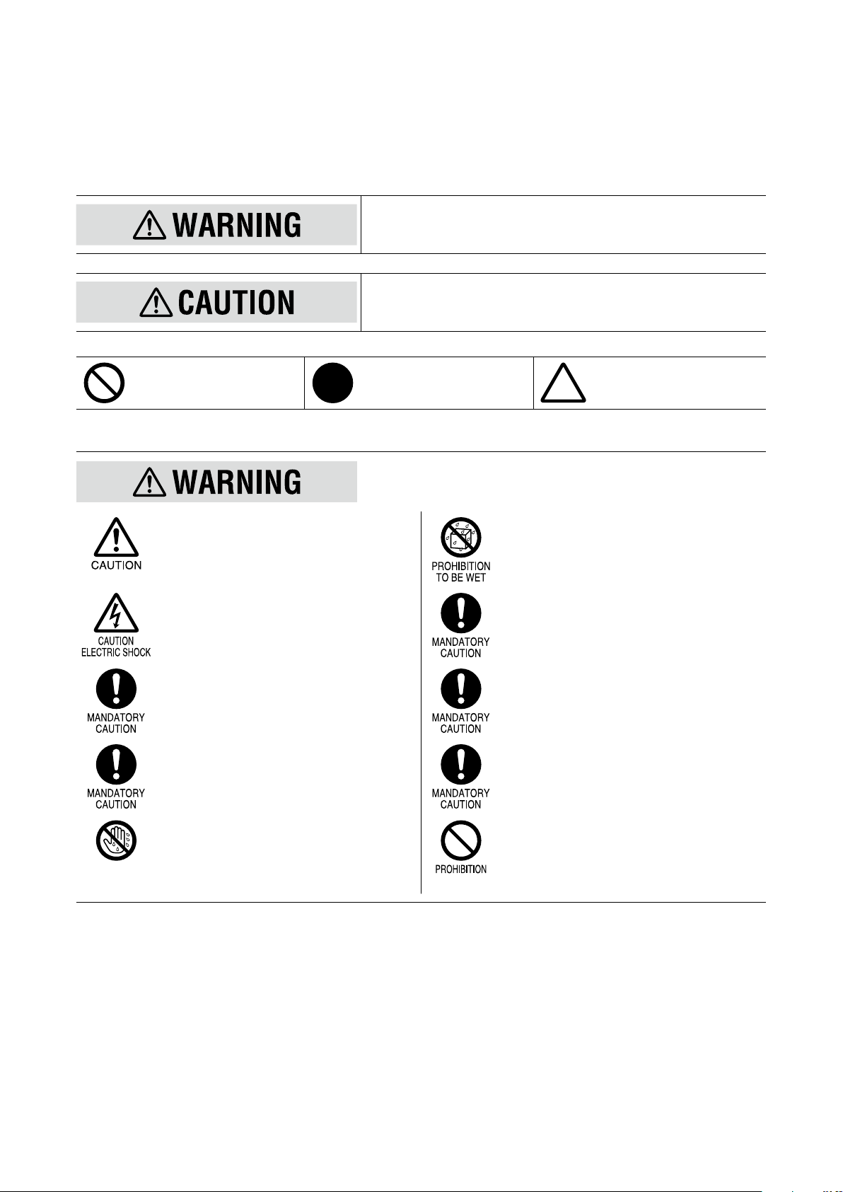
The following signs are used in this manual to provide precautions required to ensure safe usage of the unit. Please understand these signs and graphic symbols, read the manual carefully and observe the description.
The following signs show seriousness of safety hazard or damage occurred when used wrongly with the signs ignored.
Indicates a potentially hazardous situation which, if not avoided, may result in
serious injury or death.
Indicates a potentially hazardous situation which, if not avoided, may result in
injury or in property damage.
Indicates prohibitions. Indicates mandatory cautions. Indicates cautions.
PROHIBITION
WET HANDS
Make sure for safety that only qualied personnel
perform the wiring.
• Failure to do so may result in a re, electric
shock or injury.
Do not touch the terminals while the power is on.
•Doing so may result in electric shock.
Check the connection diagram carefully before
wire connection.
• Failure to do so may result in malfunction, a re
or electric shock.
Tighten the terminal screws of the Euro type connector terminal blocks with a specied torque.
• Excessive fastening may result in damage of
the screws and loose screws may occasionally
result in ignition.
Do not operate buttons with a wet hand or nger.
•Doing so may result in electric shock.
Do not splash water on the unit.
• Doing so may result in a re, electric shock or
injury.
Provide safety measures outside of the unit to
ensure safety in the whole system if an abnormality occurs due to malfunction of the unit or another
external factor affecting the unit’s operation.
Stop using the unit immediately if smokes, unusual
smell or abnormal noises come(s) from it.
• Using the unit continuously may result in a re
or electric shock.
Stop using the unit if it is dropped or damaged.
• Using the unit continuously may result in a re
or electric shock.
Do not throw the unit into the re.
• Doing so may result in rupture of the electronic
component.
5M3LU2 OPERATING MANUAL EM-2653-B Rev.0
Page 6
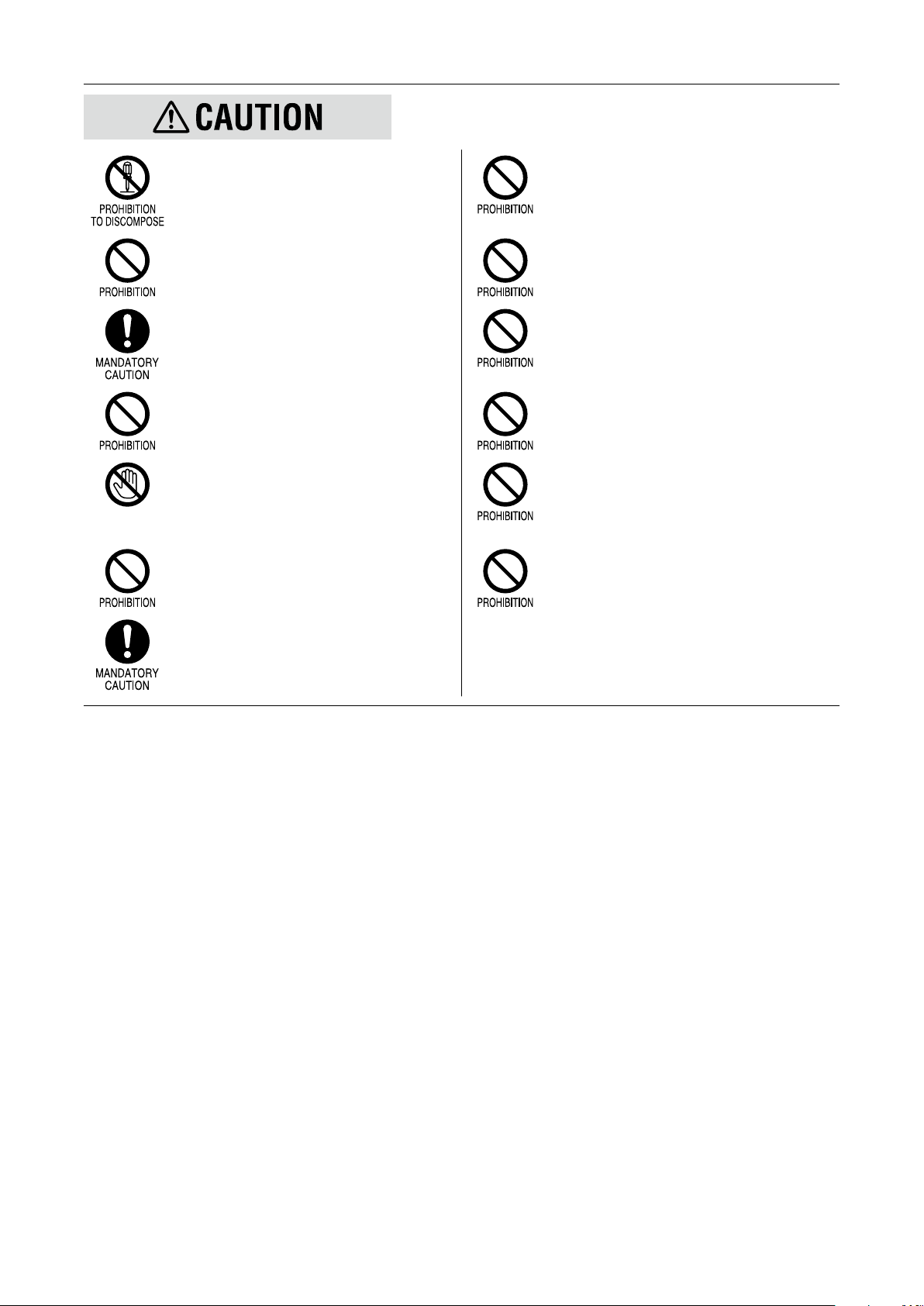
Never discompose or remodel the unit.
• Doing so may result in electric shock, malfunction or injury.
Do not press buttons with a pointed object.
•Doing so may result in malfunction of the unit.
PROHIBITION
TO CONTACT
Do not connect or remove the unit while its power
is on.
• Doing so may result in, electric shock, malfunction or injury.
Do not allow ne shavings or wire scraps to enter
the unit in machining screws or wiring.
•Doing so may result in malfunction of the unit.
Do not open the housing cover while the power or
the input is applied.
• Doing so may result in electric shock, malfunction or injury.
Do not touch the printed circuit board or the electronic components in opening the cover.
•Doing so may result in malfunction of the unit.
Do not connect other cables to the COMM (congurator jack) port than the dedicated one.
•Doing so may result in malfunction of the unit.
Use a minus screwdriver and tweezers in setting
the switches.
• Failure to do so may result in malfunction of
the unit.
Do not pull the wires to separate the Euro type
connector terminal blocks from the body.
• Doing so may result in damage of the unit or
injury.
Do not use the unit with the cover open.
•Doing so may result in malfunction of the unit.
Do not pull the wires connecting to the unit.
• Doing so may result in electric shock, damage
of the unit or injury.
Do not use the unit in the atmosphere where combustible gas is present.
• Doing so may result in inammation, ignition or
smoke.
Do not cover the ventilation slits with cables, etc.
•Doing so may result in malfunction or heating.
6M3LU2 OPERATING MANUAL EM-2653-B Rev.0
Page 7

3. POINTS OF CAUTION
3.1 BEFORE USE ....
The unit is for use in general industrial environments, therefore may not be suitable for applications which require higher
level of safety (e.g. safety or accident prevention systems) or of reliability (e.g. vehicle control or combustion control systems).
For safety, installation and maintenance of this unit must be conducted by qualied personnel.
If the unit is not used in a manner not specied by M-System, the protection provided by the equipment may be impaired.
3.2 CONFORMITY WITH EU DIRECTIVES
This product conforms to the following Low Voltage and EMC Directives.
Electromagnetic Compatibility (EMC) Directive (2004/108/EC)
EMI EN 61000-6-4: 2007/A1: 2011
EMS EN 61000-6-2: 2005
Low Voltage Directive (2006/95/EC)
EN 61010-1: 2010
Installation Category II
Pollution Degree 2
Input or output to power: Reinforced insulation (300 V)
Input to output: Basic insulation (300 V)
•This equipment is suitable for Pollution Degree 2 and Installation Category II. Reinforced insulation (signal input or output
to power input: 300 V) and basic insulation (signal input to output: 300 V) are maintained. Prior to installation, check that
the insulation class of this unit satises the system requirements.
•Altitude up to 2000 meters.
•The equipment must be mounted inside a panel.
•The actual installation environments such as panel congurations, connected devices, connected wires, may affect the
protection level of this unit when it is integrated in a panel system. The user may have to review the CE requirements in
regard to the whole system and employ additional protective measures to ensure the CE conformity.
This product conforms to the EMC Directive for electrical and electronic apparatus intended for use in industrial environments. If it is used in the residential environments, it may cause radio interference, and the user is requested to take
appropriate measures.
3.3 ENVIRONMENT
Install the unit within the installation specications.
•Indoors use
•Environmental temperature must be within -25 to +60°C (-13 to 140°F) with relative humidity within 30 to 95% RH without
condensing.
•Altitude up to 2000 meters.
•Provide sufficient space around the unit for heat dissipation.
•Install the unit in a well-ventilated place in order to prevent internal temperature rise.
•Refer to “Clustered mounting” to install several units. In mounting the unit with other equipments side by side, provide
sufficient space between them, according to the dimensions in the clustered mounting.
•Do not use the unit under the following environments:
– Where the unit is exposed to direct sunlight, rain or wind. (The unit is not designed for outdoor use.)
– Where condensation may occur due to extreme temperature changes.
– Where corrosive or ammable gas is present.
7M3LU2 OPERATING MANUAL EM-2653-B Rev.0
Page 8

– Where heavy dust, iron powder or salt is present in the air.
– Where organic solvent such like benzine, thinner, and alcohol, or strong alkaline materials such like ammonia and
caustic soda may attach to the unit, or where such materials are present in the air.
– Where the unit is subject to continuous vibration or physical impact.
– Where there are high-voltage lines, high-voltage equipments, power lines, power equipments, equipments with trans-
mission unit such like a ham radio equipment, or equipments generating large switching surges around the unit.
3.4 WIRING
•In order to prevent potential electric shock, wire the unit after turning off the power supply and making sure that the power
is not supplied to the cable.
•Be sure to conrm the name and polarity of each terminal before wiring to the Euro type connector terminal blocks.
•Do not connect anything to unused terminals.
3.5 HANDLING CAUTIONS
•The unit is designed to function as soon as power is supplied, however, a warm up for 10 minutes is required for satisfying complete performance described in the data sheet.
•Use the unit within the noted supply power voltage and rated load.
•The last measured values are held in mode transition. Take this into consideration when conguring the control system.
•Clean the surface of the unit with wet soft cloth. Do not use organic solvent such like benzine, thinner and alcohol. Doing
so may result in deformation or discoloration of the unit.
•When abnormality is found such like smokes, unusual smell and abnormal noises coming from the unit, immediately cut
the power supply and stop using it.
8M3LU2 OPERATING MANUAL EM-2653-B Rev.0
Page 9
4. FEATURES AND PREPARATION PROCEDURE OF M3LU2
4.1 FEATURES OF M3LU2
The M3LU2 is a eld congurable signal transmitter using a simulator and an indicator, without a PC or a dedicated setting
unit.
For instance, select an input type and range with the DIP switches on the unit to set input. Then apply a desired minimum
or maximum input from the simulator and press a front button to memorize the value as minimum or maximum value. Easy
and reasonable M-System’s one-step calibration (hereafter called ‘One-Step Cal’) realizes automatic I/O ranging and calibration only by pressing a button once.
4.2 PREPARATION PROCEDURE
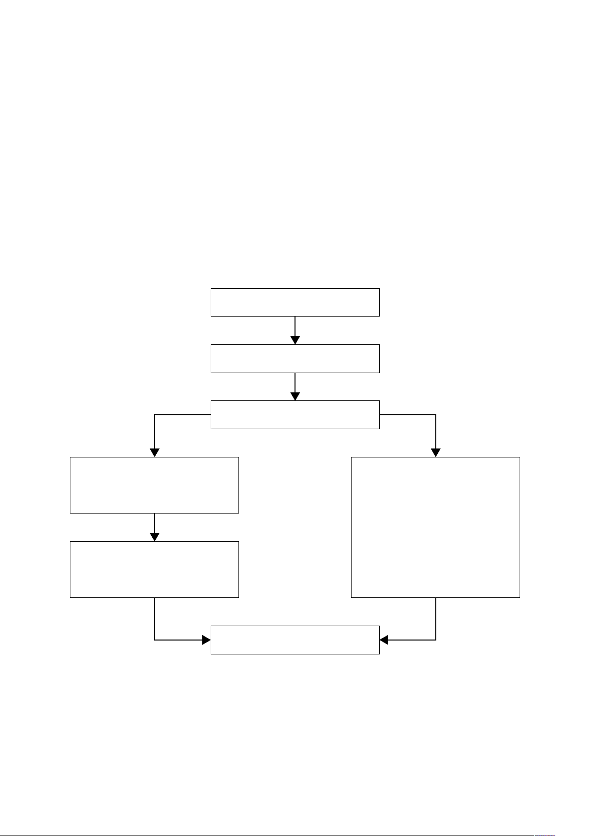
Before using the unit, perform the calibration according the following ow. The procedure depends on the conguration
options or modes.
•Two conguration modes are available with the model M3LU2-x/A, eld conguration using the DIP SW / control
buttons (hereafter called ‘DIP SW conguration’) and the PC conguration.
•The model M3LU2-x/B is for the DIP SW conguration only.
CONFIGURING DIP SW & JP2
DIP SW conguration PC conguration
INPUT RANGING
• With front control buttons and a simulator.
OUTPUT RANGING
• With front control buttons, a simulator
and a multimeter.
WIRING & MOUNTING ON DIN RAIL
POWER ON
I/O SETTING AND CALIBRATION
• Using the PC Congurator Software
(model: M3LUCFG).
STARTING OPERATION
9M3LU2 OPERATING MANUAL EM-2653-B Rev.0
Page 10
5. COMPONENT IDENTIFICATION
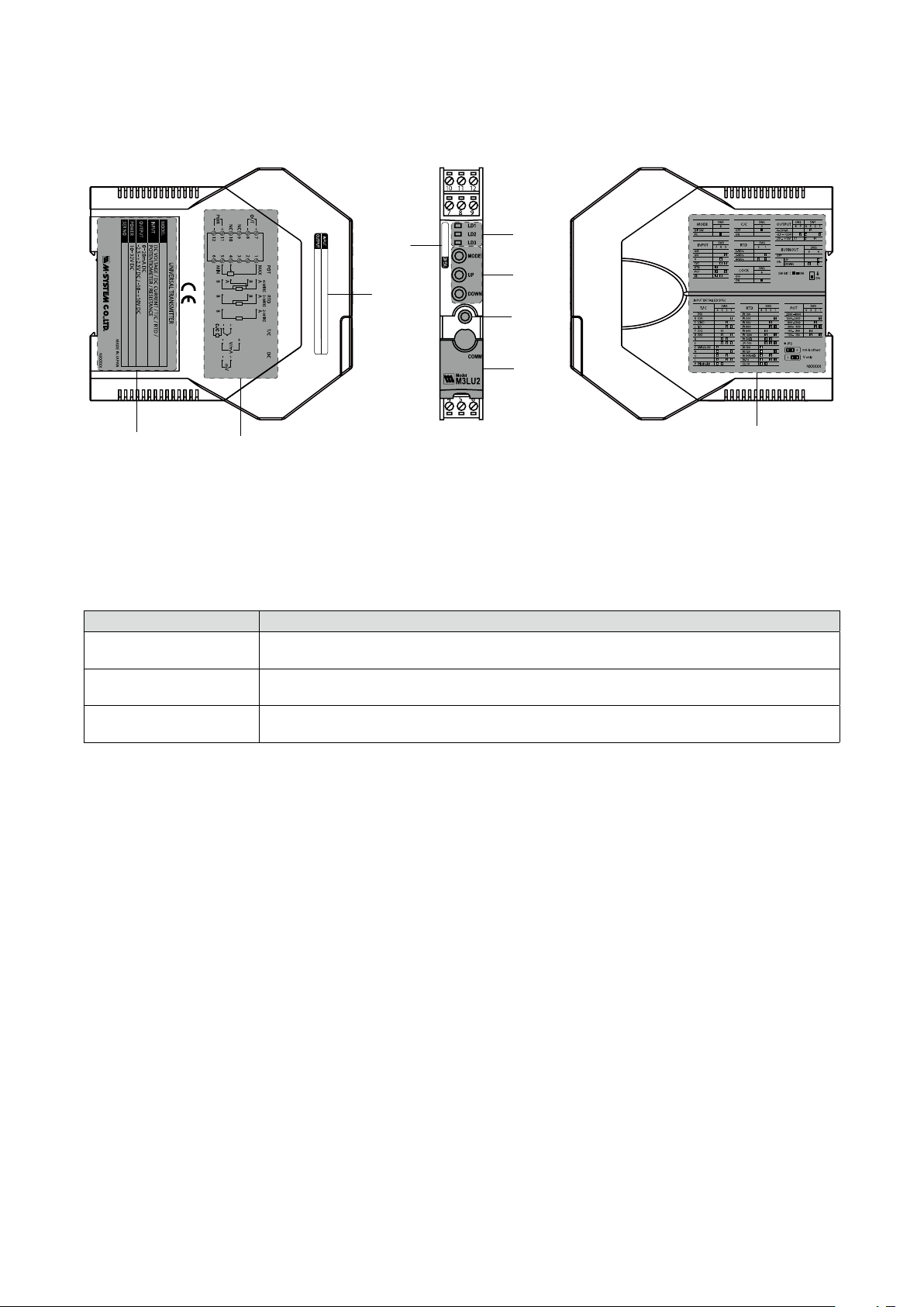
5.1 FRONT AND SIDE VIEWS
(1)
(2)
(3)
(4)
(7)
(5)
(9)
(8)
(6)
(1) LED1 (LD1), LED2 (LD2) and LED3 (LD3)
The blinking pattern (ON/blink/OFF) of the tri-color (green/amber/red) LEDs indicates a mode or an operation status of
the transmitter.
(2) MODE, UP and DOWN Buttons
Used for the I/O ranging and ne adjustments by ‘One-Step Cal’, and for reset of the parameters to the default status.
The functions of the buttons are shown in the following table.
BUTTON FUNCTION
MODE
UP
DOWN
Used to move on to the I/O Ranging Mode, Fine Adjustment Mode and RUN Mode, and to reset the
parameters to the default status.
Used to congure 100% input in the Input Ranging Mode and 100% output in the Output Ranging
Mode, and to increase the output in the Fine Adjustment Mode.
Used to congure 0% input in the Input Ranging Mode and 0% output in the Output Ranging Mode, and
to decrease the output in the Fine Adjustment Mode.
(3) Congurator jack
Used to connect with a PC using the PC Congurator Software (model: M3LUCFG) for various settings, I/O ranging
and ne adjustments.
Connect a dedicated cable between the congurator jack and the PC.
(4) Cover for congurator jack
Slide the cover to connect the cable to the congurator jack. Close the cover in the normal operation.
(5) Specication label
The model No., power input and serial No. (SER NO) are printed on the label.
(6) Connection diagram
The connection diagram for each terminal is shown.
(7) DIP SW setting
The DIP switch settings are shown.
(8) I/O range label
When I/O range indication is necessary, write in the congured ranges on the I/O range label included in the product
package and put it on the side of the unit.
(9) Tag name label
When a tag No. is specied, the unit(s) will be shipped with the tag name label put on the above position.
10M3LU2 OPERATING MANUAL EM-2653-B Rev.0
Page 11

5.1.1 STATUS INDICATOR LED
Combinations of the three front LEDs (LD1, LD2 and LD3) indicates the transmitter’s operating status by different blinking
patterns. The patterns depend on the conguration modes, DIP SW conguration and PC conguration.
Examples are shown below.
LED COLOR PATTERN
Red
Amber
Green
R
A
G
ON
Blink
OFF
■ NORMAL OPERATION (RUN) MODE
Combination of the LEDs and their blinking patterns indicate normal or abnormal operation of the unit, and are useful to
identify error modes.
•Normal operation (RUN) mode
DIP SW CONFIGURATION PC CONFIGURATION
•Error mode
ERROR DIP SW CONFIGURATION PC CONFIGURATION
Output saturated
Burnout
DIP SW error
System error
The output is below -15% or above +115%. Check the setting and input.
The sensor or the input wiring is disconnected. Check the sensor and wiring.
DIP SW conguration is inappropriate. Check the SW settings.
Indicates the CPU’s communication error.
11M3LU2 OPERATING MANUAL EM-2653-B Rev.0
Page 12

■ I/O RANGING MODE & FINE ADJUSTMENT MODE
The LED status in the I/O ranging and ne adjustments using the ‘One-Step Cal’ is shown in the following tables.
MODE LED MODE LED
Input ranging
Output ranging Fine span adjustment
Fine zero adjustment
NOTE
In the I/O ranging and ne adjustments using the PC Congurator Software (model: M3LUCFG), the LEDs are not according to the above tables.
12M3LU2 OPERATING MANUAL EM-2653-B Rev.0
Page 13
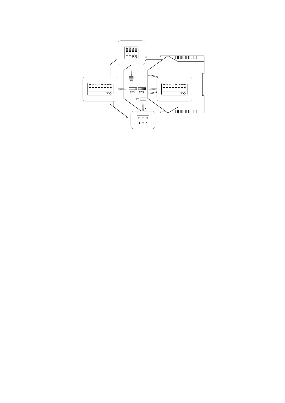
5.2 INTERNAL VIEW
(1) SW1
(2) SW2 (3) SW3
(4) JP2
(1) SW1
Sets output type.
(2) SW2
Sets wires, cold junction compensation, burnout, front control button lock and output type.
(3) SW3
Sets input type, sensor type and conguration mode.
(4) JP2
Sets input type.
13M3LU2 OPERATING MANUAL EM-2653-B Rev.0
Page 14
6. HOW TO OPEN THE COVER
■
Open the housing cover to set the DIP switches and JP2 inside the cover.
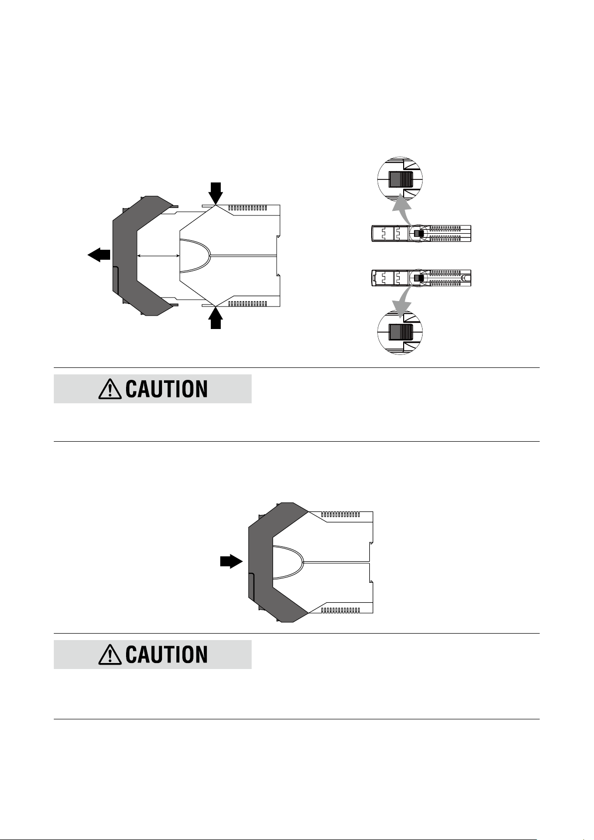
■ HOW TO OPEN THE COVER
(1) Hold the locks at the top and bottom of the unit.
(2) Slide the housing cover gently to open until it hits the latching inside the unit (approx. 3.5 cm).
Top
Front
Approx. 3.5 cm
Lock
Lock
Bottom
■
Lock
Lock
•Do not open the cover while the power or the input is applied.
•Do not touch the printed circuit board or the electronic components in opening the cover.
•Do not pull beyond where the cover is latched.
■ HOW TO CLOSE THE COVER
(1) Push the front to close the cover.
Front
•Before closing the cover, make sure that there is not a conductive foreign material attached on the printed cir-cuit board.
•Be sure to close the cover after setting.
•Be careful not to get your hand or nger caught in the cover.
•Do not force the cover closed. Doing so may result in damage of the electronic components.
14M3LU2 OPERATING MANUAL EM-2653-B Rev.0
Page 15
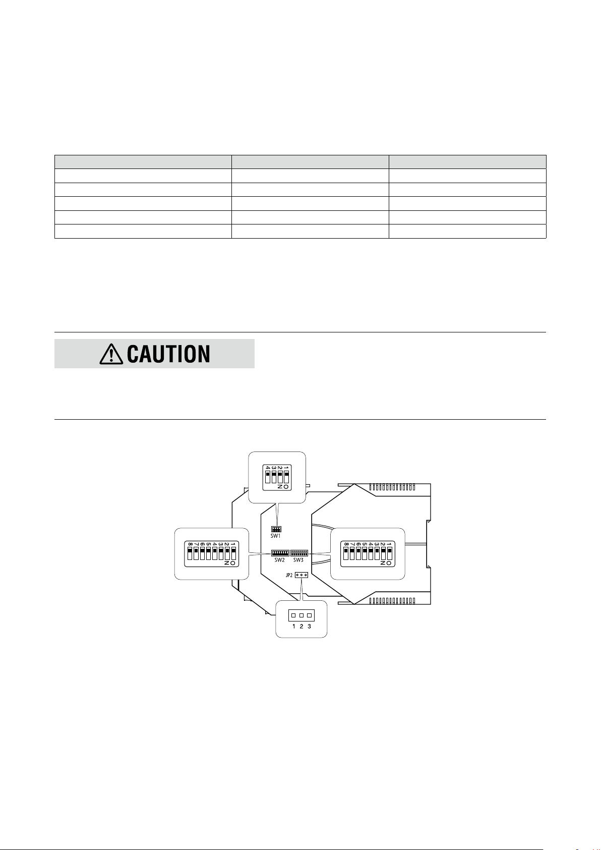
7. DIP SWITCH CONFIGURATION
SW1
This chapter describes the conguration of the I/O specications and functions using the DIP switches and the JP2.
For the PC conguration, some DIP switch settings are necessary.
7.1 DIFFERENCE BETWEEN DIP SW CONFIGURATION AND PC CONFIGURATION
The following table shows the difference between the DIP SW conguration and PC conguration.
CONFIGURATION ITEM DIP SW CONFIGURATION PC CONFIGURATION
Conguration mode SW3-8 OFF SW3-8 ON
JP2 for input type Required Required
DIP SW for input Required ----
Output type Required Required for SW1-1 through 1-4
Front control button lock As necessary As necessary
7.2 DIP SWITCH SELECTION PER I/O SPECIFICATION AND FUNCTION
Congure the DIP switches and JP2 according to your I/O specications and functions.
The unit reads the DIP-switch-calibrated conguration only once after the power supply is turned on. Set the switches with
the power supply removed. Some tools are needed to set the DIP switches and JP2.
•Set the switches and JP2 with the power supply removed.
•Use tweezers or longnose pliers to switch the JP2.
•Use a minus screwdriver with the blade edge 0.8 mm (0.03”) to set the DIP switches.
•Do not touch other electronic components except for the JP2 and DIP switches.
SW2 SW3
JP2
15M3LU2 OPERATING MANUAL EM-2653-B Rev.0
Page 16
7.2.1 CONFIGURATION MODE
With the model M3LU2-x/A, select the conguration mode (conguration method of I/O specications), DIP SW conguration or PC conguration, as shown in the following table. With the model M3LU2-x/B, turn the SW3-8 OFF.
DIP SW conguration: sets I/O specications with the DIP switches inside the cover and the front control buttons.
PC conguration: sets I/O specications with the PC Congurator Software (model: M3LUCFG).
MODE SW3-8
DIP SW OFF
PC ON
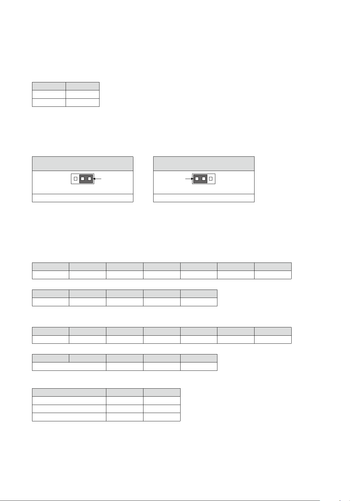
7.2.2 INPUT TYPE (JP2)
Switch the JP2 jumper according to the input specications.
Note that the JP2 setting is required with the PC conguration.
DC VOLTAGE [V] RANGE POSITION
[maximum range: -10 to +10 V DC]
Jumper
12
3
Switch the JP2 jumper to the 2-3 position. Switch the JP2 jumper to the 1-2 position.
NORMAL POSITION
(other than DC voltage [V] range)
Jumper
12
3
7.2.3 INPUT (DIP SWITCHES)
Set the DIP switches (SW2-1 through 2-5, SW3-1 through 3-7) according to the input specications. These settings are not
required with the PC conguration.
7.2.3.1 DC current input
SW3-7 SW3-6 SW3-5 SW3-4 SW3-3 SW3-2 SW3-1
OFF OFF OFF OFF OFF OFF OFF
SW2-5 SW2-4 SW2-3 SW2-2 SW2-1
OFF OFF OFF OFF OFF
7.2.3.2 DC voltage input (mV) [maximum range: -1000 to +1000 mV DC]
SW3-7 SW3-6 SW3-5 SW3-4 SW3-3 SW3-2 SW3-1
OFF OFF ON OFF OFF OFF OFF
SW2-5 SW2-4 SW2-3 SW2-2 SW2-1
Refer to Burnout OFF OFF OFF
•Burnout
BURNOUT SW2-5 SW2-4
No burnout OFF OFF
Upscale OFF ON
Downscale ON ON
16M3LU2 OPERATING MANUAL EM-2653-B Rev.0
Page 17
7.2.3.3 DC voltage input (V) [maximum range: -10 to +10 V DC]
SW3-7 SW3-6 SW3-5 SW3-4 SW3-3 SW3-2 SW3-1
OFF ON OFF OFF OFF OFF OFF
SW2-5 SW2-4 SW2-3 SW2-2 SW2-1
OFF OFF OFF OFF OFF
7.2.3.4 Thermocouple input
SW3-7 SW3-6 SW3-5 SW3-4 SW3-3 SW3-2 SW3-1
OFF ON ON Refer to Thermocouple type
SW2-5 SW2-4 SW2-3 SW2-2 SW2-1
Refer to Burnout Refer to Cold junction compensation OFF OFF
•Thermocouple type
T/C SW3-4 SW3-3 SW3-2 SW3-1
(PR) OFF OFF OFF OFF
K (CA) OFF OFF OFF ON
E (CRC) OFF OFF ON OFF
J (IC) OFF OFF ON ON
T (CC) OFF ON OFF OFF
B (RH) OFF ON OFF ON
R OFF ON ON OFF
S OFF ON ON ON
C (WRe 5-26) ON OFF OFF OFF
N ON OFF OFF ON
U ON OFF ON OFF
L ON OFF ON ON
P (Platinel II) ON ON OFF OFF
•Burnout
BURNOUT SW2-5 SW2-4
No burnout OFF OFF
Upscale OFF ON
Downscale ON ON
•Cold junction compensation
COLD JUNCTION COMPENSATION SW2-3
Enable OFF
Disable ON
17M3LU2 OPERATING MANUAL EM-2653-B Rev.0
Page 18
7.2.3.5 RTD input
SW3-7 SW3-6 SW3-5 SW3-4 SW3-3 SW3-2 SW3-1
ON OFF OFF Refer to RTD type
SW2-5 SW2-4 SW2-3 SW2-2 SW2-1
Refer to Burnout OFF Refer to RTD wires
•RTD type
RTD SW3-4 SW3-3 SW3-2 SW3-1
Pt 100 (JIS ’97, IEC) OFF OFF OFF OFF
Pt 200 OFF OFF OFF ON
Pt 300 OFF OFF ON OFF
Pt 400 OFF OFF ON ON
Pt 500 OFF ON OFF OFF
Pt 1000 OFF ON OFF ON
Pt 50 Ω (JIS ’81) OFF ON ON OFF
JPt 100 (JIS ’89) OFF ON ON ON
Ni 100 ON OFF OFF OFF
Ni 120 ON OFF OFF ON
Ni 508.4 Ω ON OFF ON OFF
Ni-Fe 604 ON OFF ON ON
Cu 10 @25°C ON ON OFF OFF
•Burnout
BURNOUT SW2-5 SW2-4
No burnout OFF OFF
Upscale OFF ON
Downscale ON ON
•RTD wires
WIRES SW2-2 SW2-1
2-wire OFF OFF
3-wire OFF ON
4-wire ON ON
18M3LU2 OPERATING MANUAL EM-2653-B Rev.0
Page 19
7.2.3.6 Resistance input
SW3-7 SW3-6 SW3-5 SW3-4 SW3-3 SW3-2 SW3-1
ON ON OFF OFF OFF OFF OFF
SW2-5 SW2-4 SW2-3 SW2-2 SW2-1
Refer to Burnout OFF Refer to Resistance wires
•Burnout
BURNOUT SW2-5 SW2-4
No burnout OFF OFF
Upscale OFF ON
Downscale ON ON
•Resistance wires
WIRES SW2-2 SW2-1
2-wire OFF OFF
3-wire OFF ON
4-wire ON ON
7.2.3.7 Potentiometer input
SW3-7 SW3-6 SW3-5 SW3-4 SW3-3 SW3-2 SW3-1
ON OFF ON Refer to Potentiometer (total resistance)
SW2-5 SW2-4 SW2-3 SW2-2 SW2-1
Refer to Burnout OFF OFF OFF
•Potentiometer (total resistance)
POTENTIOMETER
(TOTAL RESISTANCE)
2500 to 4000 Ω OFF OFF OFF OFF
1200 to 2500 Ω OFF OFF OFF ON
600 to 1200 Ω OFF OFF ON OFF
300 to 600 Ω OFF OFF ON ON
150 to 300 Ω OFF ON OFF OFF
80 to 150 Ω OFF ON OFF ON
SW3-4 SW3-3 SW3-2 SW3-1
•Burnout
BURNOUT SW2-5 SW2-4
No burnout OFF OFF
Upscale OFF ON
Downscale ON ON
19M3LU2 OPERATING MANUAL EM-2653-B Rev.0
Page 20

7.2.4 OUTPUT TYPE
Set the DIP switches (SW1-1 through 1-4, SW2-7 and 2-8) according to the output specications.
The DIP switch settings (SW1-1 through 1-4) are required with the PC conguration.
7.2.4.1 DIP SW conguration
•DC current output
SW1-4 SW1-3 SW1-2 SW1-1 SW2-8 SW2-7
OFF ON OFF OFF OFF OFF
•DC voltage output (narrow spans) [maximum range: -2.5 to +2.5 V DC]
SW1-4 SW1-3 SW1-2 SW1-1 SW2-8 SW2-7
ON OFF OFF ON OFF ON
•DC voltage output (wide spans) [maximum range: -10 to +10 V DC]
SW1-4 SW1-3 SW1-2 SW1-1 SW2-8 SW2-7
ON OFF ON OFF ON OFF
7.2.4.2 PC conguration
•DC current output
SW1-4 SW1-3 SW1-2 SW1-1
OFF ON OFF OFF
•DC voltage output (narrow spans) [maximum range: -2.5 to +2.5 V DC]
SW1-4 SW1-3 SW1-2 SW1-1
ON OFF OFF ON
•DC voltage output (wide spans) [maximum range: -10 to +10 V DC]
SW1-4 SW1-3 SW1-2 SW1-1
ON OFF ON OFF
7.2.5 FRONT CONTROL BUTTON LOCK
You can lock the button operation on the front panel to prevent inadvertent operation.
LOCK SW2-6
Unlock OFF
Lock ON
20M3LU2 OPERATING MANUAL EM-2653-B Rev.0
Page 21
8. WIRING
8mm
8mm
8.1 CAUTION IN WIRING
•Make sure for safety that only qualied personnel performs the wiring.
•In order to prevent potential electric shock, wire the unit after turning off the power supply and making sure that the
power is not supplied to the cable.
•Be sure to conrm the name and polarity of each terminal before wiring to the Euro type connector terminal blocks
(hereafter called ‘terminal block(s)’).
•Take measures to reduce noise as much as possible, e.g. by using shielded twisted pair wires for the input signal.
Ground the input shield to the most stable earth to prevent noise troubles.
•Do not connect anything to unused terminals.
•M-System offers a series of lightning surge protectors for protection against induced lightning surges. Please con-
tact M-System to choose appropriate models.
8.2 WIRING INSTRUCTIONS
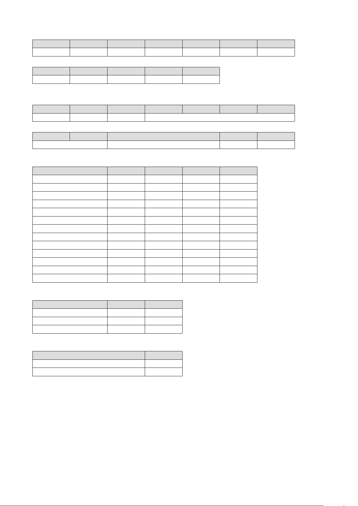
■ APPLICABLE WIRE SIZE
•Solid: 0.25 to 2.5 mm
•Stranded: 0.25 to 2.5 mm
2
(0.55 to 1.75 dia.)
2
(0.55 to 1.75 dia.)
8mm
•Tinning wire ends may cause contact failure and therefore is not recommended.
•Expose wire conductors by 8 mm (0.31”).
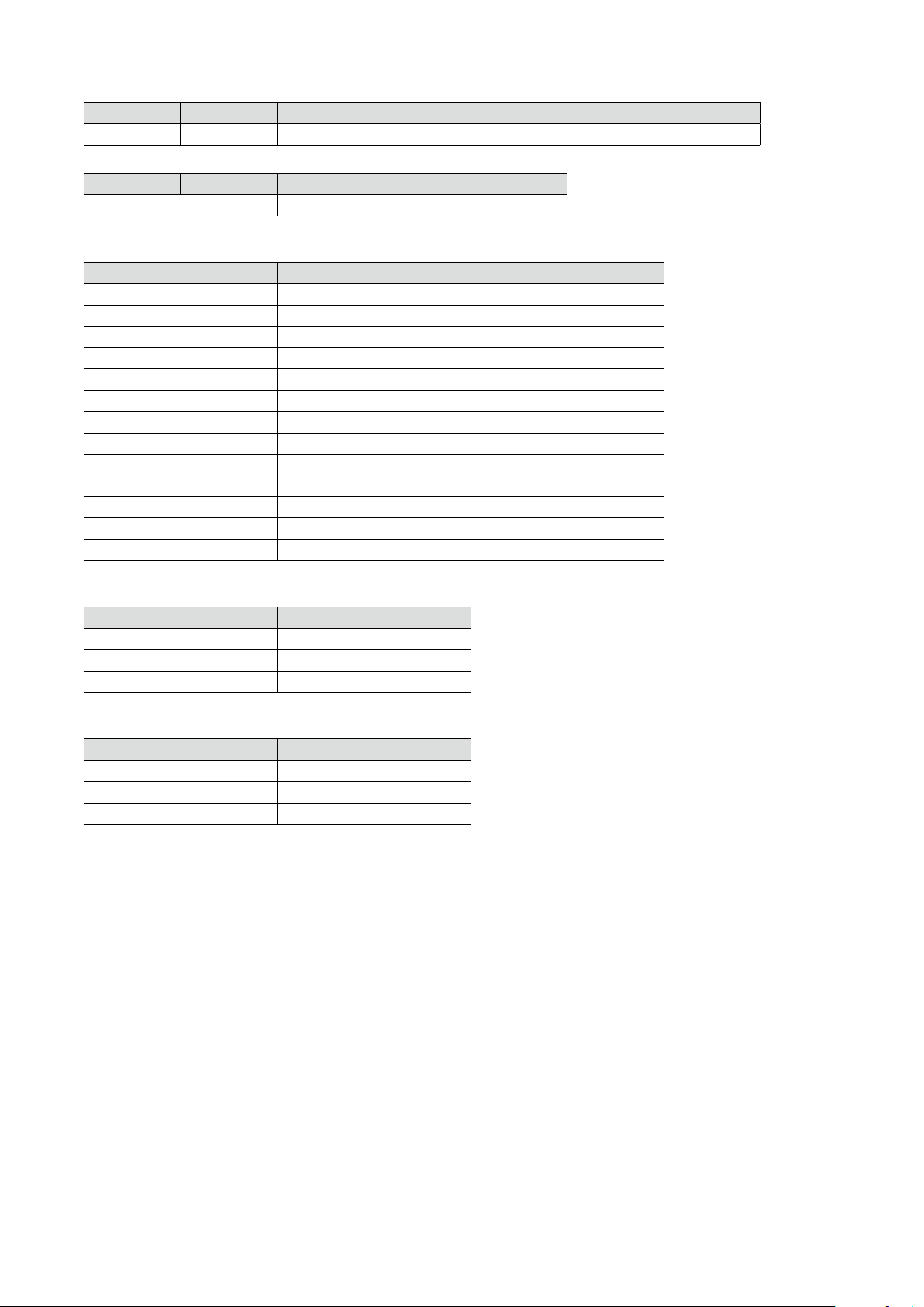
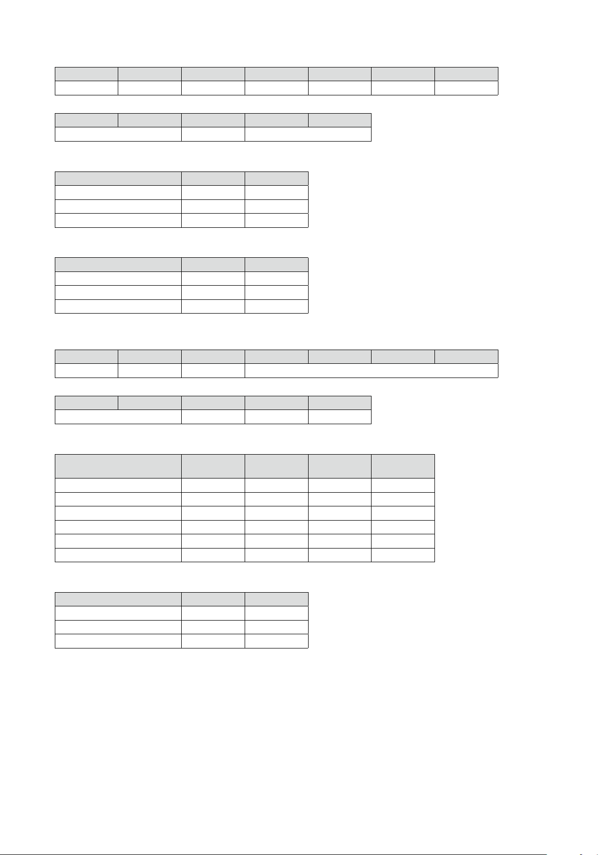
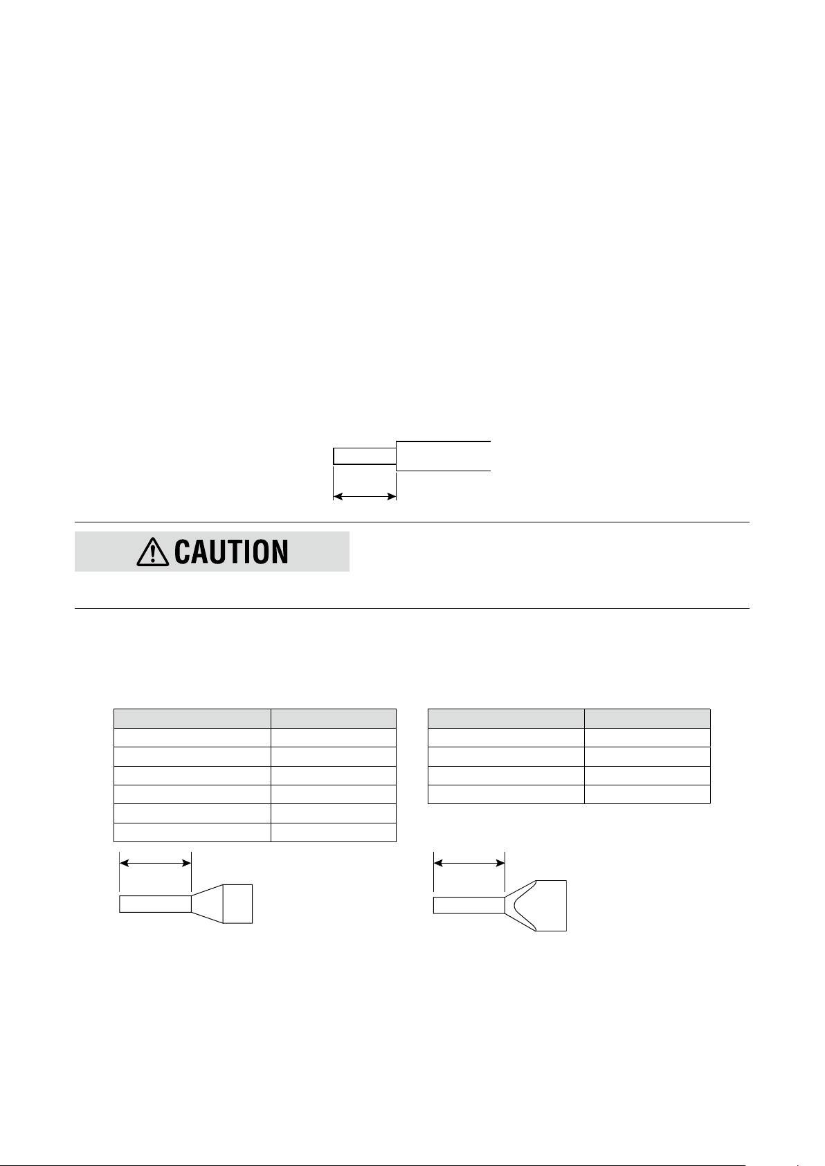
■ RECOMMENDED FERRULE
The following Phoenix Contact terminals are recommended.
•For single-wire •For twin-wire
CROSS-SECTION AREA MODEL CROSS-SECTION AREA MODEL
0.2 to 0.25 mm
0.25 to 0.34 mm
0.34 to 0.5 mm
0.5 to 0.75 mm
0.75 to 1.0 mm
1.0 to 1.5 mm
2
2
2
2
2
2
AI 0,25-8 YE 0.34 to 0.5 mm
AI 0,34-8 TQ 0.5 to 0.75 mm
AI 0,5-8 WH 0.75 to 1.0 mm
AI 0,75-8 GY 1.0 to 1.5 mm
AI 1,0-8 RD
AI 1,5-8 BK
2
2
2
2
AI-TWIN 2X 0,5-8 WH
AI-TWIN 2X 0,75-8 GY
AI-TWIN 2X 1,0-8 RD
AI-TWIN 2X 1,5-8 BK
Recommended manufacturer: Phoenix Contact GmbH & Co., KG
21M3LU2 OPERATING MANUAL EM-2653-B Rev.0
Page 22
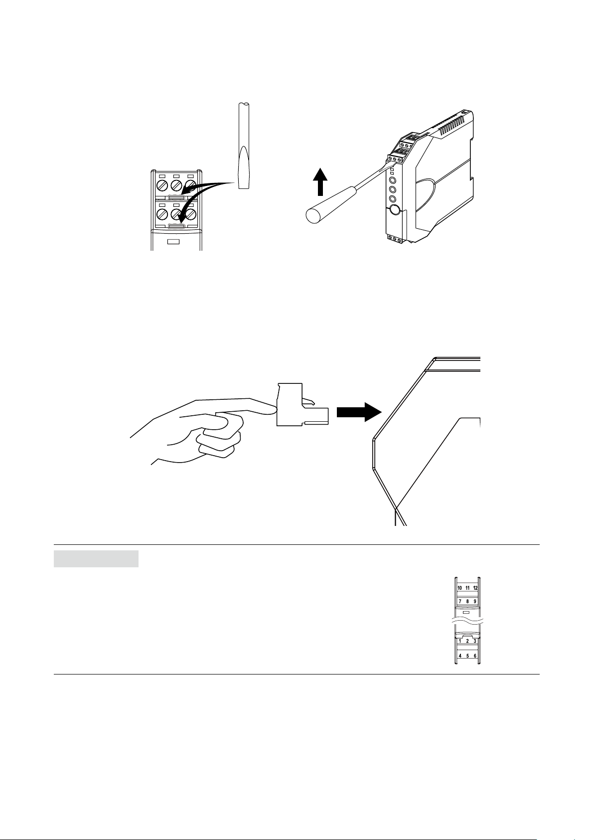
■ INSTALLATION/SEPARATION OF TERMINAL BLOCK
•Separation
Insert a minus screwdriver between the terminal block and the housing body, pull up the driver and pull out the terminal
block.
•Installation
Push the terminal block until it clicks into place.
NOTE
Match the terminal numbers of the terminal blocks with those indicated on the transmitter body in installing the blocks (gure on the right).
22M3LU2 OPERATING MANUAL EM-2653-B Rev.0
Page 23
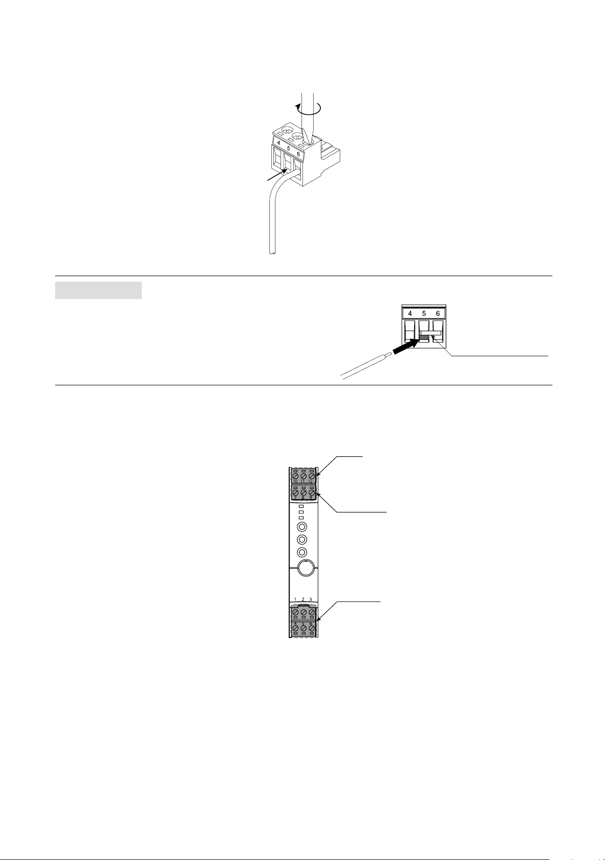
■ WIRING TO TERMINAL BLOCK
Insert a wire into the dead end of a terminal block and x it with a minus screwdriver with the blade edge 0.6 mm (0.02”)
and the blade width 3.5 mm (0.14”) (torque: 0.5 – 0.6 N∙m).
NOTE
•For a thermocouple input, replace the terminal block (4 – 5 – 6)
with the one connected with the CJC sensor included in the
package. Fasten the input wire and the CJC sensor together
on the terminal 5.
•Do not use a ferrule with insulating sleeve.
•Insert a wire under the CJC sensor (gure on the right).
CJC sensor (model: CJM)
8.3 TERMINAL ASSIGNMENT
Power
Output signal
Input signal
23M3LU2 OPERATING MANUAL EM-2653-B Rev.0
Page 24
8.4 TERMINAL CONNECTIONS
■ DC POWERED TYPE
DC
VOLT
mA
mV
–+–
■ AC POWERED TYPE
DC
VOLT
mA
mV
–+–
+
+
T/C
ext. wire
+
–
*1
CJC
SENSOR
T/C
ext. wire
+
–
*1
CJC
SENSOR
2-wire
RTD
3-wire
RTD
A
4-wire
RTD
A
B
+
–
B
B
POT.
max.
+
1
A
B
3
2
3
4
min.
2
5
1
–
A
B
7
8
11
12
+
OUTPUT
–
+
DC POWER
–
*2
6
CONFIGURATOR
2-wire
RTD
3-wire
RTD
A
4-wire
RTD
A
B
+
POT.
max.
A
B
A
–
B
B
B
min.
JACK
+
1
3
2
3
4
2
5
1
–
7
8
10
12
+
OUTPUT
–
U
AC POWER
V
*2
6
CONFIGURATOR
JACK
*1 Replace the Euro Type Connector Terminal Block (4 – 5 – 6) with the one connected with the CJC Sensor, included in the package.
The CJC Sensor is secured to the terminal 6.
Loosen only the terminal 4 – 5 and connect the T/C extension wires.
*2 Be aware that the AC power and DC power connect to different terminals.
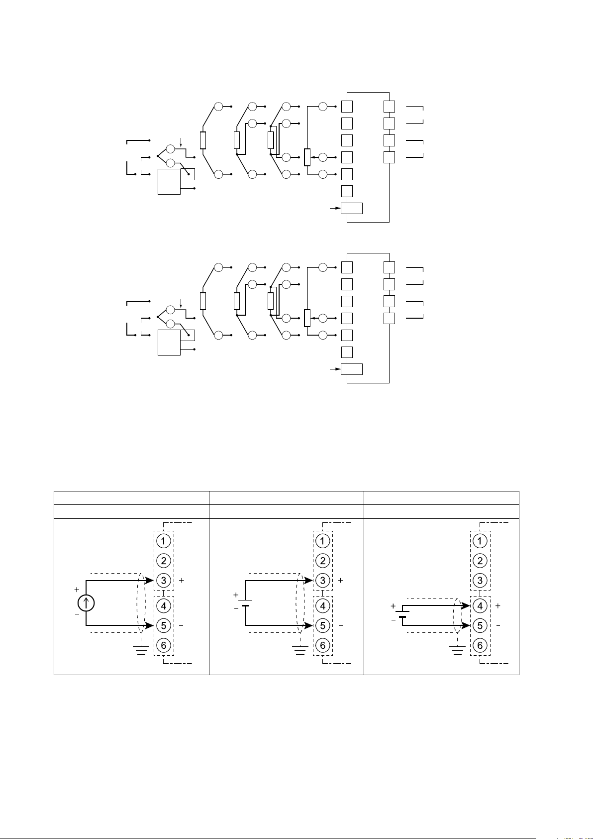
8.4.1 WIRING INPUT
8.4.1.1 DC voltage/current input
Connect DC voltage or current wires.
DC current input DC voltage input (V) DC voltage input (mV)
Maximum range: 0 to 20 mA DC Maximum range: -10 to +10 V DC Maximum range: -1000 to +1000m V DC
DC current
Ground
(resistance
100 ohms or less)
DC voltage (V)
Ground
(resistance
100 ohms or less)
DC voltage (mV)
Ground
(resistance
100 ohms or less)
24M3LU2 OPERATING MANUAL EM-2653-B Rev.0
Page 25
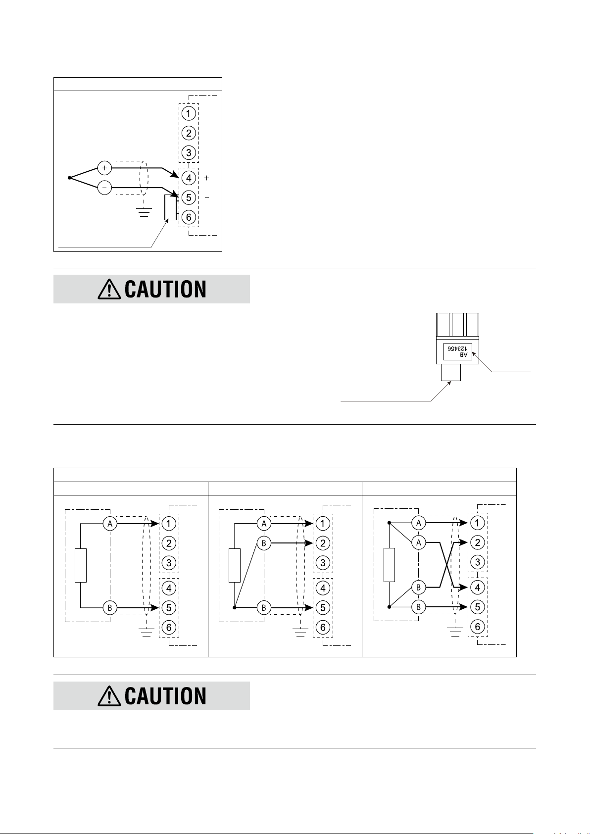
8.4.1.2 Thermocouple input
RTD or resistance
RTD or resistance
RTD or resistance
Connect a thermocouple or extension wires.
Thermocouple input
Extension
T/C
Ground
(resistance
100 ohms or less)
CJC sensor (model: CJM)
Wire
•Wire the unit with the thermocouple using the extension wires with
the same characteristics as the thermocouple.
•The CJC sensor is calibrated to a particular unit and not interchangeable with another. Match the serial No. of the unit and the
sensor (gure on the right).
•Be careful not to change the temperature around the terminal block.
Take care that wind from a fan does not hit it directly.
•Be careful not to separate the CJC sensor from the terminal block.
Do not loosen the screw on the terminal 6. If you did, connect the
CJC sensor to the terminals 5 and 6.
Serial No.
CJC sensor (model: CJM)
8.4.1.3 RTD/resistance input
Connect a RTD or a resistance. Connect according to the RTD/resistance wires.
RTD/resistance input
2-wire 3-wire 4-wire
Ground
(resistance
100 ohms or less)
Ground
(resistance
100 ohms or less)
Ground
(resistance
100 ohms or less)
•The leadwire resistance including internal resistance such like a lightning surge protector and a barrier must be maximum 20 Ω per wire.
•The excitation is 0.3 mA. Use a RTD with excitation 0.3 mA or more.
25M3LU2 OPERATING MANUAL EM-2653-B Rev.0
Page 26

8.4.1.4 Potentiometer input
Connect a potentiometer.
Potentiometer input
Potentiometer
Max.
Min.
Ground
(resistance
100 ohms or less)
8.4.2 WIRING OUTPUT
Voltage or current output is provided depending on the output setting.
Output
Output
Ground
(resistance
100 ohms or less)
8.4.3 WIRING POWER
Connect power according to the power input code. The power specications are shown in the following table.
CODE RATING ALLOWABLE RANGE & POWER CONSUMPTION
M2 100 to 240 V AC 85 to 264 V AC, 47 to 66 Hz
Approx. 4 VA at 100 V
Approx. 5 VA at 200 V
Approx. 6 VA at 264 V
R4 10 to 32 V DC 9 to 36 V DC, approx. 3 W
DC power AC power
AC power
DC power
•Be aware that the AC power and DC power connect to different terminals.
•For DC power, conrm the polarity.
26M3LU2 OPERATING MANUAL EM-2653-B Rev.0
Page 27
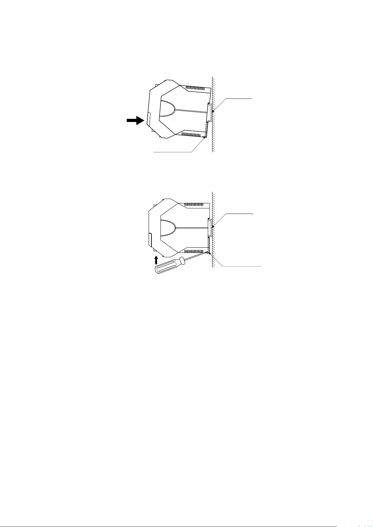
9. INSTALLATION
■ DIN RAIL MOUNTING
Set the unit so that its DIN rail adaptor is at the bottom. Position the upper hook at the rear side of the unit on the DIN rail
and push in the lower.
DIN Rail
35mm wide
Spring Loaded
DIN Rail Adaptor
■ REMOVAL
Push down the DIN rail adaptor utilizing a minus screwdriver and pull.
DIN Rail
35mm wide
Spring Loaded
DIN Rail Adaptor
27M3LU2 OPERATING MANUAL EM-2653-B Rev.0
Page 28

10. CALIBRATION
‘Calibration’ means I/O ranging or output ne adjustments using the front control buttons. M-System’s ‘One-Step-Cal’ calibration technique realizes automatic I/O ranging and adjustment.
This chapter describes ow and operation procedure of the calibration.
You can also carry out the calibration using the PC Congurator Software (model: M3LUCFG). For detailed information,
refer to the M3LUCFG users manual.
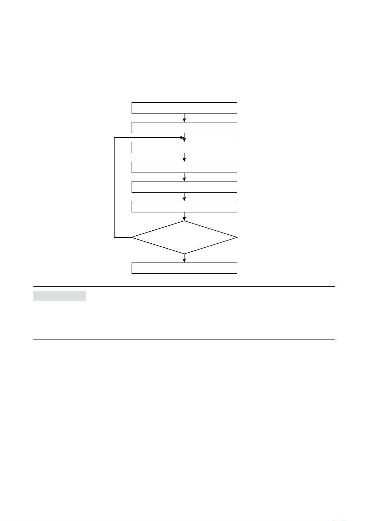
10.1 CALIBRATION FLOW
The calibration includes I/O Ranging Mode and Fine Adjustment Mode. Hold down the MODE button to shift each mode
from the RUN Mode. The mode to shift depends on the time to hold down the button.
The following chart shows the calibration ow.
Hold down
Press
Press
Fine Adjustment ?
1 – 2 s
FINE ZERO
ADJUSTMENT MODE
or
FINE SPAN
ADJUSTMENT MODE
or
RUN MODE
*1
Hold down
Press
Press
I/O Ranging ?
INPUT
RANGING
MODE
OUTPUT
RANGING
MODE
Amber LED
Green LED
Red LED
≥ 5s
Apply simulated
0% input signal.
Apply simulated
100% input signal.
Adjust simulated
input until the output
meter shows
desired 0% output.
Adjust simulated
input until the output
meter shows
desired 100% output.
OFF
ON
Blink
Hold down
Hold down
Hold down
Hold down
MODE button
UP button
DOWN button
*2
0% INPUT
CONFIGURED
*2
100% INPUT
CONFIGURED
*2
0% OUTPUT
CONFIGURED
*2
100% OUTPUT
CONFIGURED
RUN MODE
*1
*1 In the RUN Mode, the green LD1 blinks (PC conguration), or turns on (DIP SW conguration).
*2 When you set 0% or 100% input/output ranges, keep pressing UP or DOWN button until the LD1 blinks for approx. 2 seconds and
turns off, which indicates the setup is complete. When you release the button, the LD1 is returned to ON. Therefore hold down the
button until the LD1 turns OFF.
28M3LU2 OPERATING MANUAL EM-2653-B Rev.0
Page 29

10.2 INPUT & OUTPUT RANGING
After the DIP switch setting is complete, set up the precise input and output range using the front control buttons. Be sure
that the front control button function is enabled with the DIP switch setting (SW2-6 OFF).
10.2.1 OUTLINE OF I/O RANGING
■ PREPARATION
Mount the DIP-SW-congured M3LU2 on to a DIN rail.
Connect the M3LU2 to a simulator and a multimeter and to a power source according to the terminal connections.
■ INPUT RANGING
•In the Input Ranging Mode, apply the desired minimum input level from the simulator and hold down DOWN button
until the LD1 blinks and then turns OFF.
•Then apply the desired maximum input level and hold down UP button until the LD1 blinks and then turns OFF.
[Example 1] Setting input to 0 – 5 V DC
Maximum input range: -10 to +10 V DC
0% input ranging: apply 0 V DC and hold down DOWN button
100% input ranging: apply 5 V DC and hold down UP button
-10 V
0% input ranging
0 V
0 V
Max. input range
Input ranging
+5 V
+10 V
100% input ranging
5 V
NOTE
•Input ranging is not needed in using the default value.
•100% input ranging value must be greater than 0% value.
•Set the input within the maximum range with the minimum span or more. With inappropriate input level, the input rang-
ing is not carried out even in holding down UP or DOWN button. (The LD1 does not change.)
•There is no stated order of setting 0% and 100% levels or no limitations of entering values for multiple times within one
step of Ranging Mode.
•Signal level is not stored when UP or DOWN button is released before the LD1 turns OFF.
29M3LU2 OPERATING MANUAL EM-2653-B Rev.0
Page 30

■ OUTPUT RANGING
•In the Output Ranging Mode, increase or decrease the simulated input until the meter shows the desired minimum
output level. Hold down DOWN button until the LD1 blinks and then turns OFF.
•Then increase or decrease the simulated input until the meter shows the desired maximum output level. Hold down
UP button until the LD1 blinks and then turns OFF.
[Example 2] Setting output to 0 – 16 mA DC (input 0 – 5 V DC [Example 1])
Maximum output range: 0 – 20 mA DC
0% output ranging: increase or decrease a simulated input until the meter shows 0 mA DC and hold down
DOWN button.
100% output ranging: increase or decrease a simulated input until the meter shows 16 mA DC and hold
down UP button.
-10 V
0% input ranging
0% output ranging
0 V
0 mA
0 mA
0 V
Max. input range
Input ranging
Max. output range
Output ranging
+5 V
+10 V
100% input ranging
5 V
16 mA
20 mA
100% output ranging
16 mA
IMPORTANT
•Use a simulator to adjust the desired output.
•A different signal from that in the input ranging may be applied.
•Increase or decrease a simulated input while conrming the output with a multimeter.
•Even if the input ranging is performed after the output ranging, another output ranging is not needed.
NOTE
•Output ranging is not needed in using the default value.
•100% output ranging value must be greater than 0% value.
•Set the output within the maximum range with the minimum span or more. With inappropriate output level, the output
ranging is not carried out even in holding down UP or DOWN button. (The LD1 does not change.)
•There is no stated order of setting 0% and 100% levels or no limitations of entering values for multiple times within one
step of the Ranging Mode.
•Signal level is not stored when UP or DOWN button is released before the LD1 turns OFF.
30M3LU2 OPERATING MANUAL EM-2653-B Rev.0
Page 31

10.2.2 MAXIMUM RANGE, MINIMUM SPAN AND DEFAULT VALUE OF INPUT
The maximum range, minimum span and default value of the input are shown in the following tables. The default value
means initial 0% and 100% input when the DIP switch setting is changed.
10.2.2.1 DC current input
MAXIMUM RANGE MINIMUM SPAN DEFAULT VALUE
0 to 20 mA DC 1 mA 4 to 20 mA DC
10.2.2.2 DC voltage input (mV)
MAXIMUM RANGE MINIMUM SPAN DEFAULT VALUE
-1000 to +1000 mV DC 4 mV 0 to 1000 mV DC
10.2.2.3 DC voltage input (V)
MAXIMUM RANGE MINIMUM SPAN DEFAULT VALUE
-10 to +10 V DC 1 V 1 to 5 V DC
10.2.2.4 Thermocouple input
Minimum span: 20°C (36°F)
Default value: same as conformance range in °C
THERMOCOUPLE °C °F
MAXIMUM RANGE CONFORMANCE RANGE MAXIMUM RANGE CONFORMANCE RANGE
(PR) 0 to 1760 0 to 1760 32 to 3200 32 to 3200
K (CA) -270 to +1370 -150 to +1370 -454 to +2498 -238 to +2498
E (CRC) -270 to +1000 -170 to +1000 -454 to +1832 -274 to +1832
J (IC) -210 to +1200 -180 to +1200 -346 to +2192 -292 to +2192
T (CC) -270 to +400 -170 to +400 -454 to +752 -274 to +752
B (RH) 100 to 1820 400 to 1760 212 to 3308 752 to 3200
R -50 to +1760 200 to 1760 -58 to +3200 392 to 3200
S -50 to +1760 0 to 1760 -58 to +3200 32 to 3200
C (WRe 5-26) 0 to 2315 0 to 2315 32 to 4199 32 to 4199
N -270 to +1300 -130 to +1300 -454 to +2372 -202 to +2372
U -200 to +600 -200 to +600 -328 to +1112 -328 to +1112
L -200 to +900 -200 to +900 -328 to +1652 -328 to +1652
P (Platinel II) 0 to 1395 0 to 1395 32 to 2543 32 to 2543
31M3LU2 OPERATING MANUAL EM-2653-B Rev.0
Page 32
10.2.2.5 RTD input
Minimum span: 20°C (36°F)
Default value: same as maximum range in °C
RTD °C °F
MAXIMUM RANGE MAXIMUM RANGE
Pt 100 (JIS ’97, IEC) -200 to +850 -328 to +1562
Pt 200 -200 to +850 -328 to +1562
Pt 300 -200 to +850 -328 to +1562
Pt 400 -200 to +850 -328 to +1562
Pt 500 -200 to +850 -328 to +1562
Pt 1000 -200 to +850 -328 to +1562
Pt 50 Ω (JIS ’81) -200 to +649 -328 to +1200
JPt 100 (JIS ’89) -200 to +510 -328 to +950
Ni 100 -80 to +260 -112 to +500
Ni 120 -80 to +260 -112 to +500
Ni 508.4 Ω -50 to +200 -58 to +392
Ni-Fe 604 -200 to +200 -328 to +392
Cu 10 @25°C -50 to +250 -58 to +482
10.2.2.6 Resistance input
MAXIMUM RANGE MINIMUM SPAN DEFAULT VALUE
0 to 4000 Ω 10 Ω 0 to 4000 Ω
10.2.2.7 Potentiometer input
MAXIMUM RANGE
(TOTAL RESISTANCE)
2500 to 4000 Ω 2% of total resistance 0 to 100%
1200 to 2500 Ω
600 to 1200 Ω
300 to 600 Ω
150 to 300 Ω
80 to 150 Ω
MINIMUM SPAN DEFAULT VALUE
10.2.3 MAXIMUM RANGE, MINIMUM SPAN AND DEFAULT VALUE OF OUTPUT
The maximum range, minimum span and default value of the output are shown in the following tables. The default value
means initial 0% and 100% output when the DIP switch setting is changed.
10.2.3.1 DC current output
MAXIMUM RANGE MINIMUM SPAN DEFAULT VALUE
0 to 20 mA DC 1 mA 4 to 20 mA DC
10.2.3.2 DC voltage output (narrow spans)
MAXIMUM RANGE MINIMUM SPAN DEFAULT VALUE
-2.5 to +2.5 V DC 250 mV 0 to 1 V DC
10.2.3.3 DC voltage output (wide spans)
MAXIMUM RANGE MINIMUM SPAN DEFAULT VALUE
-10 to +10 V DC 1 V 1 to 5 V DC
32M3LU2 OPERATING MANUAL EM-2653-B Rev.0
Page 33
10.2.4 OPERATION PROCEDURE OF I/O RANGING
Perform the I/O ranging in the following procedure.
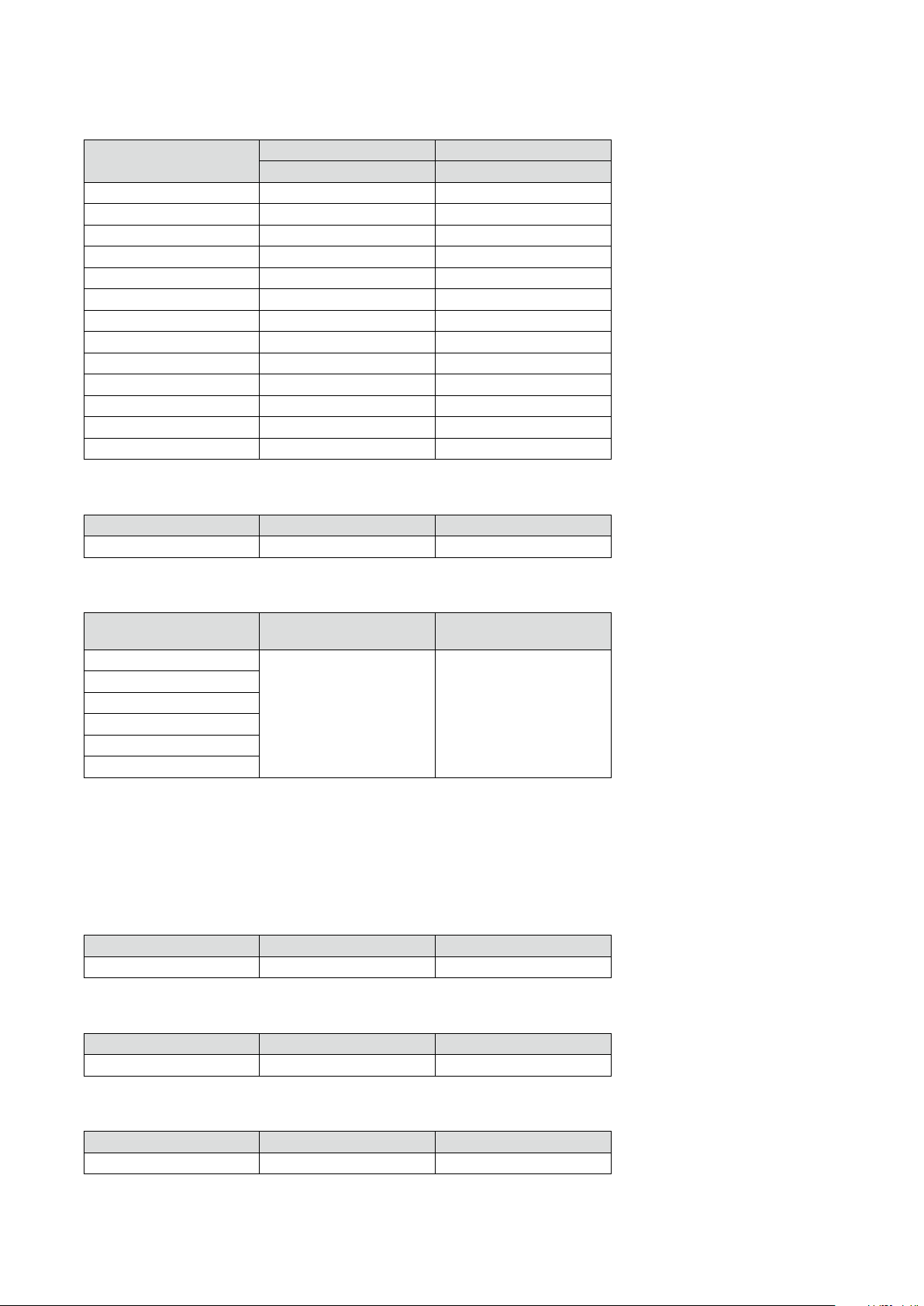
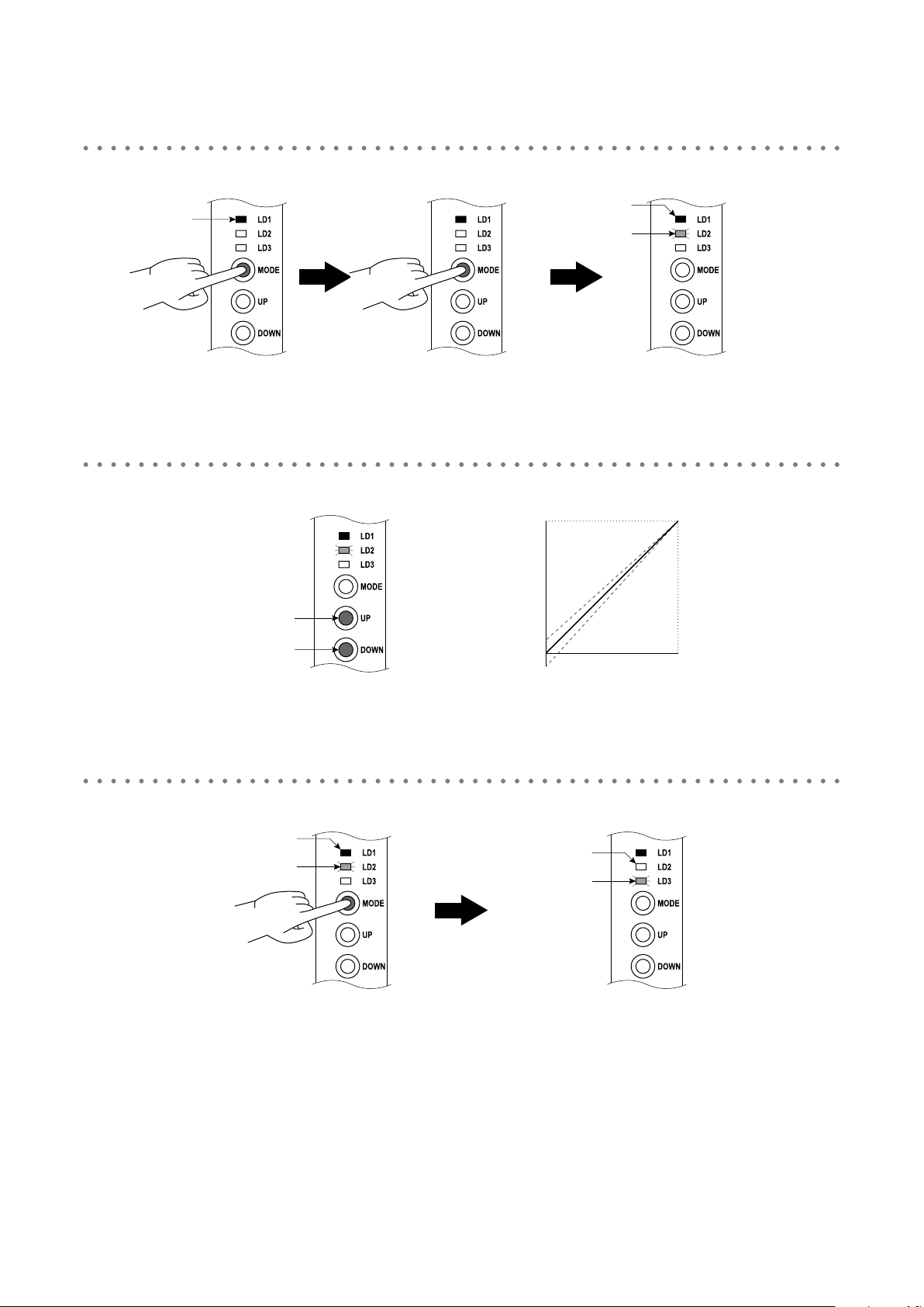
In the RUN Mode, hold down MODE button for 5 seconds or more until the LD1 red LED is ON.
1
Green ON
or
blinking
5 sec. or more
•Conrm that the LD1 green LED is ON (DIP SW conguration) or blinking (PC conguration). Then hold down
MODE button for 5 seconds or more until the LD1 red LED is ON.
•The LD2 red LED starts blinking indicating the Input Ranging Mode.
Apply the desired minimum input level and hold down DOWN button until the LD1 turns OFF.
Red ON
Red blinking
2
Red ON
Red blinking
•Hold down DOWN button, and the LD1 red LED blinks in approx. 2 sec. and then turns OFF in approx. 2 sec.
•The LD1 turning OFF means completion of 0% input ranging. Hold down DOWN button until the LD1 turns OFF.
•Skip to the next procedure when 0% input ranging is not necessary.
Apply the desired maximum input level and hold down UP button until the LD1 turns OFF.
Rapid
red blinking
Approx. 2 sec.
OFF Red ON
Approx. 2 sec.
Release button
0% input ranging completed
3
Red ON
Red blinking
Rapid
red blinking
Approx. 2 sec. Approx. 2 sec.
OFF
Red ON
Release button
100% input ranging completed
•Hold down UP button, and the LD1 red LED blinks in approx. 2 sec. and then turns OFF in approx. 2 sec.
•The LD1 turning OFF means completion of 100% input ranging. Hold down UP button until the LD1 turns OFF.
•Skip to the next procedure when 100% input ranging is not necessary.
33M3LU2 OPERATING MANUAL EM-2653-B Rev.0
Page 34
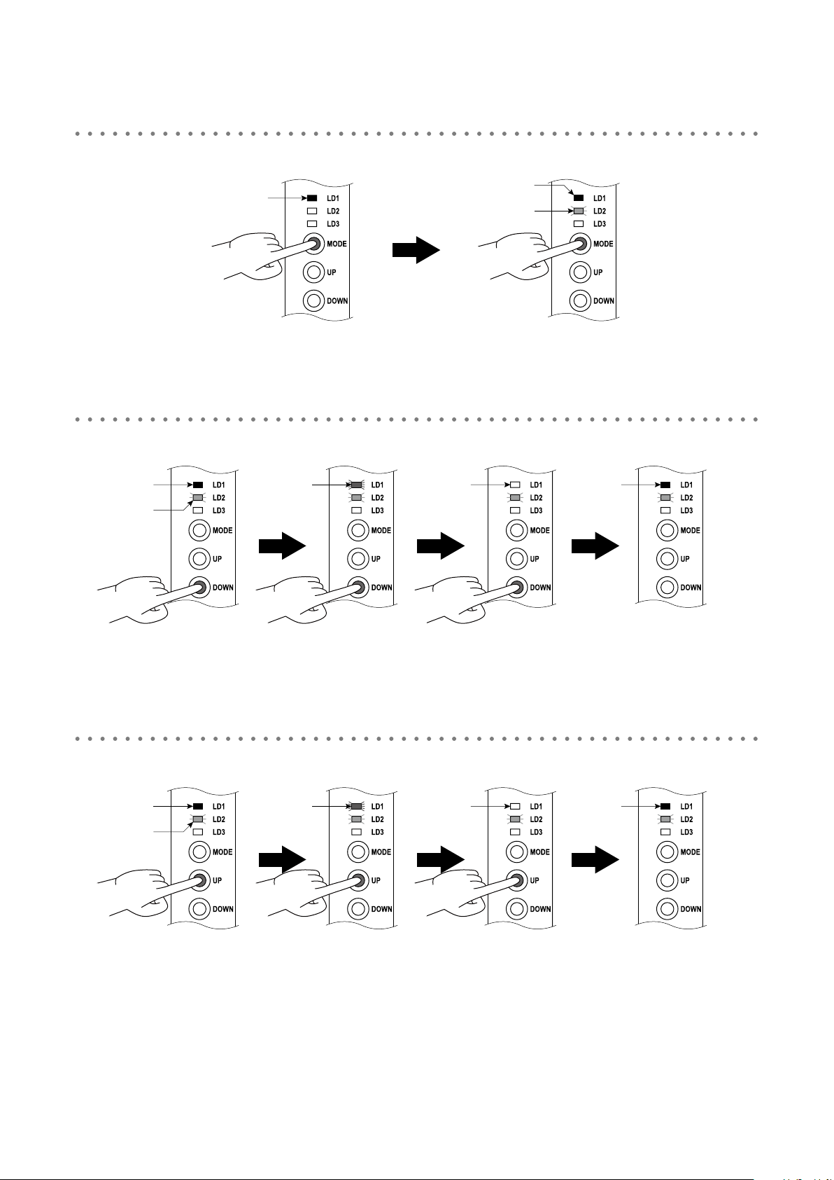
Press MODE button to go on to the Output Ranging Mode.
4
Red ON
Red blinking
Press once
•Press MODE button once to go on to the Output Ranging Mode.
•The LD2 turns OFF and the LD3 red LED starts blinking indicating the Output Ranging Mode.
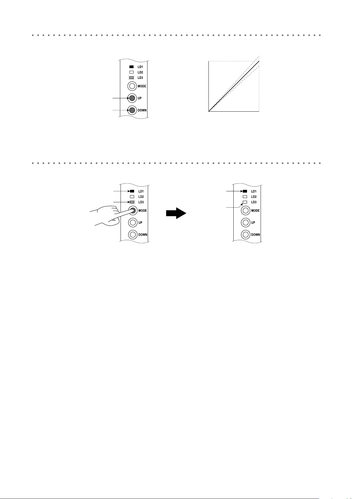
Increase or decrease the simulated input until the meter shows the desired minimum output level. Hold
down DOWN button until the LD1 turns OFF.
5
OFF
Red blinking
Red ON Red ONOFF
Red blinking
•Hold down DOWN button, and the LD1 red LED blinks in approx. 2 sec. and then turns OFF in approx. 2 sec.
•The LD1 turning OFF means completion of 0% output ranging. Hold down DOWN button until the LD1 turns OFF.
•Skip to the next procedure when 0% output ranging is not necessary.
Increase or decrease the simulated input until the meter shows the desired maximum output level. Hold
down UP button until the LD1 turns OFF.
6
Red ON
Red blinking
Rapid
red blinking
Approx. 2 sec.Approx. 2 sec.
Rapid
red blinking
Approx. 2 sec. Approx. 2 sec.
OFF
Release button
0% ouput ranging completed
Red ON
Release button
100% ouput ranging completed
•Hold down UP button, and the LD1 red LED blinks in approx. 2 sec. and then turns OFF in approx. 2 sec.
•The LD1 turning OFF means completion of 100% output ranging. Hold down UP button until the LD1 turns OFF.
•Skip to the next procedure when 100% output ranging is not necessary.
34M3LU2 OPERATING MANUAL EM-2653-B Rev.0
Page 35

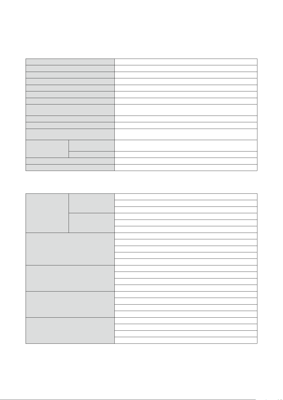
Press MODE button to return to the RUN Mode.
7
Green ON
Red ON
Red blinking
Press once
•Press MODE button once to return to the RUN mode.
•The LD3 turns OFF and the LD1 green LED is ON (DIP SW conguration) or blinking (PC conguration).
or
blinking
OFF
35M3LU2 OPERATING MANUAL EM-2653-B Rev.0
Page 36
10.3 FINE ADJUSTMENT MODE
Perform the ne zero and span adjustments to correct the deviation between the output signal and a device on site. Be
sure that the front control button function is enabled with the DIP switch setting (SW2-6 OFF).
Note that M-System does not warrant the adjustments by the customer.
Each time the adjustment is performed, signal level is overwritten and is stored even when the power is off.
10.3.1 OUTLINE OF FINE ADJUSTMENT
The following owchart shows the ne zero/span adjustments.
POWER ON
Warming up (10 min. or more)
Moving on to output ne zero adjustment
Adjusting output with UP/DOWN buttons
Moving on to output ne span adjustment
Adjusting output with UP/DOWN buttons
Readjustment
Conrming output value
(operation check)
Adjustment completed
Measurement started
NOTE
•Warm up measuring instruments, equipment and other devices on site for the time specied in each manual, and operate the unit in a stable condition.
•Adjustable ranges are as follows:
Fine zero adjustment -15 to +15%
Fine span adjustment 85 to 115%
36M3LU2 OPERATING MANUAL EM-2653-B Rev.0
Page 37
10.3.2 OPERATION PROCEDURE OF FINE ADJUSTMENT
Perform the ne adjustment in the following procedure.
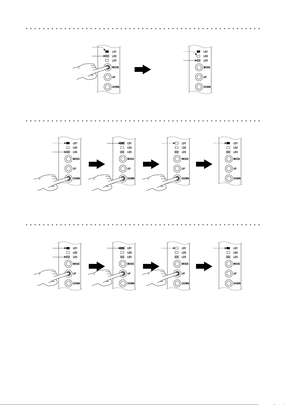
Hold down MODE button for 1 to 2 seconds and release the button to go on to the Fine Zero Adjustment
Mode.
1
Green ON
or
blinking
•Conrm that the LD1 green LED is ON (DIP SW conguration) or blinking (PC conguration). Then hold down
MODE button for 1 to 2 seconds and release the button. The LD1 red LED will be ON.
•The LD2 green LED starts blinking indicating the Fine Zero Adjustment Mode.
Use UP (increase) and DOWN (decrease) buttons to adjust the output to 0%. Check the output with a multim-
eter.
2
Hold down
for 1 to 2 sec.
Release button
Output
Red ON
Green blinking
Increase output
Decrease output
•Adjust the output value to 0% regardless of the input.
•Increase the output with UP button, and decrease with DOWN.
•Skip to the next procedure when ne zero adjustment is not necessary.
Press MODE button to go on to the Fine Span Adjustment Mode.
UP (increase)
DOWN (decrease)
↑
↓
Input
3
Red ON
Green blinking
Green blinking
Press once
•Press MODE button once to go on to the Fine Span Adjustment Mode.
•The LD2 turns OFF and the LD3 green LED starts blinking indicating the Fine Span Adjustment Mode.
OFF
37M3LU2 OPERATING MANUAL EM-2653-B Rev.0
Page 38
Use UP (increase) and DOWN (decrease) buttons to adjust the output to 100%. Check the output with a mul-
↑
timeter.
4
Output
Increase output
UP (increase)
DOWN (decrease)
↓
Decrease output
•Adjust the output value to 100% regardless of the input.
•Increase the output with UP button, and decrease with DOWN.
•Skip to the next procedure when ne span adjustment is not necessary.
Press MODE button to return to the RUN mode.
Input
5
Red ON
Green blinking
Press once
•Press MODE button once to return to the RUN Mode.
•The LD3 turns OFF and the LD1 green LED is ON (DIP SW conguration) or blinking (PC conguration).
Green ON
or
bllinking
OFF
38M3LU2 OPERATING MANUAL EM-2653-B Rev.0
Page 39

11. CHECKING, MAINTENANCE, INITIALIZATION OF PARAMETERS
11.1 CHECKING
(1) Terminal wiring: Check that all cables are correctly connected according to the connection diagram.
(2) DIP SW setting: Check that the switches are set to appropriate positions.
(3) Power input voltage: Check voltage across the terminal 10 – 12 (AC) or 11 – 12 (DC) with a multimeter.
(4) Input: Check that the input signal is within 0 to 100% of full-scale.
If the DC voltage (mV), thermocouple, RTD, resistance, potentiometer input or their extension wires is/are disconnected, the output goes over 100% (below 0% with downscale protection) due to burnout function. Conrm the status
indicator LED pattern and check leadwires in such a case.
(5) Output: Check that the load resistance meets the described specications.
11.2 MAINTENANCE
Perform the periodic calibration as stated below.
■ CALIBRATION
Warm up the unit for 10 minutes or more, apply 0, 25, 50, 75 and 100% input to the unit, and make sure that the output
is 0, 25, 50, 75 and 100% respectively within the prescribed accuracy. In case the output is deviated from the accuracy,
perform the ne zero/span adjustment.
11.3 INITIALIZATION OF PARAMETERS
You can reset the DIP-SW-congured parameters (I/O ranging and ne adjustments) to the default status. Reset the parameters in the following procedure.
(1) Turn off the power supply to the unit, open the housing cover and set the SW2-1 to OFF and SW2-2 to ON position.
(2) Close the cover and turn on the power while pressing MODE button.
(3) Wait until green LED blinks at the LD1, LD2 and LD3.
(4) Turn off the power, open the cover and reset the SW2-1 and SW2-2 to the previous position.
(5) Close the cover and turn on the power again.
39M3LU2 OPERATING MANUAL EM-2653-B Rev.0
Page 40
12. APPENDICES
12.1 SPECIFICATIONS
12.1.1 GENERAL SPECIFICATIONS
Construction Small-sized front terminal structure
Connection Euro type connector terminal
Housing material Flame-resistant resin (gray)
Isolation Input to output to power
Overrange output -15 to +115% (negative current output is not available)
Zero adjustment -15 to +15% (front)
Span adjustment 85 to 115% (front)
Burnout (other than current or voltage (V) input) Upscale, downscale or no burnout selectable; Also detects wire breakdown and
overrange input exceeding the electrical design limit for DC input.
Linearization (T/C, RTD input) Standard
Cold junction compensation (T/C input) CJC sensor (included) to be attached to the input terminals
Status indicator LED Tri-color (green/amber/red) LED; Blinking patterns indicate operation status of the
transmitter.
Conguration DIP SW conguration Input type, sensor type, burnout action, RTD/resistance wires, cold junction com-
pensation, output type, conguration mode, front control button lock
PC conguration Refer to 12.2 PC CONFIGURATOR SOFTWARE.
Calibration I/O ranging and ne adjustment via ‘One-Step Cal’ calibration or PC
Congurator connection 2.5 dia. miniature jack; RS-232-C level
12.1.2 INPUT SPECIFICATIONS
Input types and ranges are shown in the following table.
DC Current Input resistance: 50 Ω resistor incorporated
Maximum range: 0 to 20 mA DC
Minimum span: 1 mA
mV & Voltage Input resistance: ≥ 1 MΩ
Maximum range: refer to Table 1
Minimum span: refer to Table 1
Thermocouple Input resistance: ≥ 1 MΩ
Maximum range: refer to Table 2
Burnout sensing: ≤ 4 µA
Conformance range: refer to Table 2
Minimum span: refer to Table 2
RTD (2-wire, 3-wire or 4-wire) Excitation: ≤ 0.3 mA
Maximum range: refer to Table 3
Allowable leadwire resistance: max. 20 Ω per wire
Minimum span: refer to Table 3
Resistance (2-wire, 3-wire or 4-wire) Excitation: ≤ 0.3 mA
Maximum range: 0 to 4000 Ω
Allowable leadwire resistance: max. 20 Ω per wire
Minimum span: 10 Ω
Potentiometer Excitation: ≤ 0.3 mA
Maximum range: refer to Table 5
Allowable leadwire resistance: max. 20 Ω per wire
Minimum span: 2%
40M3LU2 OPERATING MANUAL EM-2653-B Rev.0
Page 41

12.1.3 OUTPUT SPECIFICATIONS
Output types and ranges are shown in the following table.
DC Current Maximum range: 0 – 20 mA DC
Minimum span: 1 mA
Conformance range: 0 – 23 mA DC
Offset: Lower range can be any specic value within the output range provided
that the minimum span is maintained.
Load resistance: Output drive 15 V max. at 20 mA
(Range: Load resistance)
0 – 20 mA : ≤ 750 Ω
DC Voltage Narrow spans
Maximum range: -2.5 – +2.5 V DC
Minimum span: 250 mV
Conformance range: -3 – +3 V DC
Wide spans
Maximum range: -10 – +10 V DC
Minimum span: 1 V
Conformance range: -11.5 – +11.5 V DC
Offset: Lower range can be any specic value within the output range provided
that the minimum span is maintained.
Load resistance: Output drive 10 mA max.; 5 mA for negative output
(Range: Load resistance)
0 – 10 V : ≥ 1 kΩ
-10 – 0 V : ≥ 2 kΩ
0 – 2.5 V : ≥ 250 Ω
-2.5 – 0 V : ≥ 500 Ω
12.1.4 INSTALLATION
Power comsumption AC power M2: 100 – 240 V AC Operational voltage range 85 – 264 V AC, 47 – 66 Hz
Approx. 4 VA at 100 V
Approx. 5 VA at 200 V
Approx. 6 VA at 264 V
DC power R4: 10 – 32 V DC Operational voltage range 9 – 36 V DC
Ripple 10% p-p max.
Approx. 3 W
Operating temperature -25 to +60°C (-13 to +140°F)
Operating humidity 30 to 95% RH (non-condensing)
Mounting DIN rail
Weight 100 g (3.53 oz)
12.1.5 PERFORMANCE
Accuracy See Table 1 to 6.
Cold junction compensation error ±1.0°C at 0 – 50°C (±1.8°F at 32 – 122°F)
Temp. coefficient ±0.015%/°C [±0.008%/°F] at -5 to +55°C [23 to 131°F] of max. range
±0.03%/°C [±0.016%/°F] for the following conditions:
•DC,T/Cinputspans≤10mV
•RTD,potentiometer,resistancespans≤80Ω
•inanambientexceeding55°C[131°F]orbelow-5°C[23°F]
Response time ≤ 0.2 sec. (0 – 90%, DC input)
(With the Option A, the Sync Filter set to the fastest frequency on the PC Congurator Software. Default is set to have 0.5 sec. response.)
Burnout response ≤ 10 sec.
Line voltage effect ±0.1% over voltage range
Insulation resistance ≥ 100 MΩ with 500 V DC
Dielectric strength 2000 V AC @ 1 minute (input to output to power to ground)
41M3LU2 OPERATING MANUAL EM-2653-B Rev.0
Page 42

12.1.6 STANDARDS & APPROVALS
EU conformity EMC Directive (2004/108/EC)
EMI EN 61000-6-4: 2007/A1: 2011
EMS EN 61000-6-2: 2005
Low Voltage Directive (2006/95/EC)
EN 61010-1: 2010
Installation Category II
Pollution Degree 2
Input or output to power: Reinforced insulation (300 V)
Input to output: Basic insulation (300 V)
12.1.7 I/O TYPE, MAXIMUM RANGE & ACCURACY
[Table 1] DC input
INPUT TYPE MINIMUM SPAN MAXIMUM RANGE
ACCURACY
DC Current 1 mA 0 to 20 mA DC ±0.1%
DC Millivolt 4 mV -1000 to +1000 mV DC ±10 μV at F.S. input ≤ 50 mV
±40 μV at F.S. input ≤ 200 mV
±60 μV at F.S. input ≤ 500 mV
±80 μV at F.S. input > 500 mV
DC Voltage 1 V -10 to +10 V DC ±0.1%
*1 Or ±0.1% of span, whichever is greater.
[Table 2] Thermocouple input
T/C °C °F
MIN.
SPAN
MAXIMUM
RANGE
ACCURACY
*2
CONFORMANCE
RANGE
MIN.
SPAN
MAXIMUM
RANGE
(PR) 20 0 to 1760 ±1.00 0 to 1760 36 32 to 3200 ±1.80 32 to 3200
K (CA) 20 -270 to +1370 ±0.25 -150 to +1370 36 -454 to +2498 ±0.45 -238 to +2498
E (CRC) 20 -270 to +1000 ±0.20 -170 to +1000 36 -454 to +1832 ±0.36 -274 to +1832
J (IC) 20 -210 to +1200 ±0.25 -180 to +1200 36 -346 to +2192 ±0.45 -292 to +2192
T (CC) 20 -270 to +400 ±0.25 -170 to +400 36 -454 to +752 ±0.45 -274 to +752
B (RH) 20 100 to 1820 ±0.75 400 to 1760 36 212 to 3308 ±1.35 752 to 3200
R 20 -50 to +1760 ±0.50 200 to 1760 36 -58 to +3200 ±0.90 392 to 3200
S 20 -50 to +1760 ±0.50 0 to 1760 36 -58 to +3200 ±0.90 32 to 3200
C (WRe 5-26) 20 0 to 2315 ±0.25 0 to 2315 36 32 to 4199 ±0.45 32 to 4199
N 20 -270 to +1300 ±0.30 -130 to +1300 36 -454 to +2372 ±0.54 -202 to +2372
U 20 -200 to +600 ±0.20 -200 to +600 36 -328 to +1112 ±0.36 -328 to +1112
L 20 -200 to +900 ±0.25 -200 to +900 36 -328 to +1652 ±0.45 -328 to +1652
P (Platinel II) 20 0 to 1395 ±0.25 0 to 1395 36 32 to 2543 ±0.45 32 to 2543
*2 [Accuracy + Cold Junction Compensation Error 1.0°C (1.8°F)] or ±0.1% of span, whichever is greater.
*1
ACCURACY
*2
CONFORMANCE
RANGE
42M3LU2 OPERATING MANUAL EM-2653-B Rev.0
Page 43

[Table 3] RTD input
RTD °C °F
*3
MIN. SPAN MAXIMUM RANGE
ACCURACY
MIN. SPAN MAXIMUM RANGE
ACCURACY
Pt 100 (JIS ’97, IEC) 20 -200 to +850 ±0.15 36 -328 to +1562 ±0.27
Pt 200 20 -200 to +850 ±0.15 36 -328 to +1562 ±0.27
Pt 300 20 -200 to +850 ±0.15 36 -328 to +1562 ±0.27
Pt 400 20 -200 to +850 ±0.15 36 -328 to +1562 ±0.27
Pt 500 20 -200 to +850 ±0.15 36 -328 to +1562 ±0.27
Pt 1000 20 -200 to +850 ±0.15 36 -328 to +1562 ±0.27
Pt 50 Ω (JIS ’81) 20 -200 to +649 ±0.15 36 -328 to +1200 ±0.27
JPt 100 (JIS ’89) 20 -200 to +510 ±0.15 36 -328 to +950 ±0.27
Ni 100 20 -80 to +260 ±0.15 36 -112 to +500 ±0.27
Ni 120 20 -80 to +260 ±0.15 36 -112 to +500 ±0.27
Ni 508.4 Ω 20 -50 to +200 ±0.15 36 -58 to +392 ±0.27
Ni-Fe 604 20 -200 to +200 ±0.15 36 -328 to +392 ±0.27
Cu 10 @25°C 20 -50 to +250 ±0.50 36 -58 to +482 ±0.90
*3 Or ±0.1% of span, whichever is greater.
[Table 4] Resistance input
MINIMUM SPAN MAXIMUM RANGE
ACCURACY
*4
10 Ω 0 to 4000 Ω ±0.1 Ω
*4 Or ±0.1% of span, whichever is greater.
*3
[Table 5] Potentiometer input
MINIMUM SPAN MAXIMUM RANGE
ACCURACY
*5
(TOTAL RESISTANCE)
2% 2500 to 4000 Ω
±0.1 Ω
1200 to 2500 Ω
600 to 1200 Ω
300 to 600 Ω
150 to 300 Ω
80 to 150 Ω
*5 Or ±0.1% of span, whichever is greater.
[Table 6] Output
OUTPUT TYPE MINIMUM SPAN MAXIMUM RANGE CONFORMANCE RANGE
DC Current
1 mA
*6
0 to 20 mA DC
0 to 23 mA DC
*7
DC Voltage 250 mV -2.5 to +2.5 V DC -3 to +3 V DC
1 V -10 to +10 V DC -11.5 to +11.5 V DC
*6 For current output, overall accuracy degrades another 0.1% with spans ≤ 2 mA.
*7 Negative overrange current below 0 mA is not available.
43M3LU2 OPERATING MANUAL EM-2653-B Rev.0
Page 44

12.1.8 CALCULATION EXAMPLES OF OVERALL ACCURACY
■ DC INPUT
(1) 0 to 200 mV DC
Absolute value accuracy [Table 1]: 40 μV
40 μV ÷ 200000 μV × 100 = 0.02% < 0.1%
➠ Overall accuracy = ±0.1% of span
(2) 0 to 4 mV DC
Absolute value accuracy [Table 1]: 10 μV
10 μV ÷ 4000 μV × 100 = 0.25% > 0.1%
➠ Overall accuracy = ±0.25% of span
■ THERMOCOUPLE INPUT
(1) K thermocouple, -150 to +1370°C
Absolute value accuracy [Table 2]: 0.25°C
CJC error (1.0°C) added: 1.25°C
1.25°C ÷ (1370°C – -150°C) × 100 = 0.082% < 0.1%
➠ Overall accuracy including CJC error = ±0.1% of span
(2) K thermocouple, 50 to 150°C
Absolute value accuracy [Table 2]: 0.25°C
CJC error (1.0°C) added: 1.25°C
1.25°C ÷ (150°C – 50°C) × 100 = 1.25% > 0.1%
➠ Overall accuracy including CJC error = ±1.25% of span
■ RTD INPUT
(1) Pt 100, -200 to 800°C
bsolute value accuracy [Table 3]: 0.15°C
0.15°C ÷ (800°C – -200°C) × 100 = 0.015% < 0.1%
➠ Overall accuracy = ±0.1% of span
(2) Pt 100, 0 to 100°C
Absolute value accuracy [Table 3]: 0.15°C
0.15°C ÷ 100°C × 100 = 0.15% > 0.1%
➠ Overall accuracy = ±0.15% of span
■ RESISTANCE INPUT
(1) 0 to 1000 Ω
Absolute value accuracy [Table 4]: 0.1 Ω
0.1 Ω ÷ 1000 Ω × 100 = 0.01% < 0.1%
➠ Overall accuracy = ±0.1% of span
(2) 0 to 50 Ω
Absolute value accuracy [Table 4]: 0.1 Ω
0.1 Ω ÷ 50 Ω × 100 = 0.2% > 0.1%
➠ Overall accuracy = ±0.2% of span
■ POTENTIOMETER INPUT
(1) 300 to 800 Ω (total resistance 1000 Ω)
Absolute value accuracy [Table 5]: 0.1 Ω
0.1 Ω ÷ (800 Ω – 300 Ω) × 100 = 0.02% < 0.1%
➠ Overall accuracy = ±0.1% of span
(2) 30 to 80 Ω (total resistance 100 Ω)
Absolute value accuracy [Table 5]: 0.1 Ω
0.1 Ω ÷ (80 Ω – 30 Ω) × 100 = 0.2% > 0.1%
➠ Overall accuracy = ±0.2% of span
44M3LU2 OPERATING MANUAL EM-2653-B Rev.0
Page 45

12.2 PC CONFIGURATOR SOFTWARE
The I/O settings and calibration are congurable with the PC Congurator Software (model: M3LUCFG). It is convenient
to set the same I/O specications to several units or the items which are not available with the DIP SW conguration or
‘One-Step Cal’ calibration. Whether the I/O settings are available or not depends on the conguration option code and
conguration mode.
A dedicated cable is required to connect the unit to the PC.
PORT PC CONFIGURATOR CABLE MODEL NO.
RS-232-C MCN-CON
USB COP-US
The PC Congurator Software is freely downloadable at M-System’s web site (http://www.m-system.co.jp/).
Software download model No.: M3CFG
■ I/O CONFIGURATION
The following table shows congurable items with the PC Congurator Software. For detailed information on the PC conguration, refer to the M3LUCFG users manual (EM-9197-A).
ITEM M3LU2-x/A M3LU2-x/B
PC CONFIGURATION
(SW3-8 ON)
Input type X ---- ----
Sensor wires X ---- ----
PV range (upper, lower) X ---- ----
PV damping (time constant) X X ----
Burnout X ---- ----
Cold junction compensation X ---- ----
Transfer function X X ----
AO type X ---- ----
AO range (upper, lower) X ---- ----
ADC conversion rate X X X
Custom TC X ---- ----
Custom RTD X ---- ----
Linearization table setting X X ----
DIP SW CONFIGURATION
(SW3-8 OFF)
■ CALIBRATION
‘One-Step Cal’ calibration (I/O ranging) and DAC trimming (ne adjustments) are congurable with the PC Congurator
Software regardless of the conguration option code and conguration mode.
■ REMARKS
For detailed information on the PC conguration, refer to the M3LUCFG users manual (EM-9197-A).
45M3LU2 OPERATING MANUAL EM-2653-B Rev.0
Page 46

12.3 MODEL NUMBERING
Code number: M3LU2–[1]/[2][3]
INPUT – Field-selectable
DC Current & Voltage
Current: 0 – 20 mA DC
Millivolt: -1000 – +1000 mV DC
Voltage: -10 – +10 V DC
Thermocouple
(PR), K, E, J, T, B, R, S, C (WRe 5-26), N, U, L, P (Platinel II)
RTD
Pt 100, Pt 200, Pt 300, Pt 400, Pt 500, Pt 1000, Ni 100, Ni 120, Ni 508.4 Ω, Ni-Fe 604, Cu 10 @25°C,
Pt 50 Ω, JPt 100
Potentiometer
Total resistance 80 – 4000 Ω
Resistance
0 – 4000 Ω
OUTPUT – Field-selectable
Current
0 – 20 mA DC
Voltage
-2.5 – +2.5 V DC
-10 – +10 V DC
[1] POWER INPUT
AC Power
M2: 100 – 240 V AC (Operational voltage range 85 – 264 V, 47 – 66 Hz)
DC Power
R4: 10 – 32 V DC (Operational voltage range 9 – 36 V, ripple 10% p-p max.)
[2] CONFIGURATION OPTIONS
A: PC and eld congurable
B: Field congurable
[3] OPTIONS
blank: none
/Q: With options (specify the specication)
SPECIFICATIONS OF OPTION: Q
COATING (For the detail, refer to M-System’s web site.)
/C01: Silicone coating
/C02: Polyurethane coating
/C03: Rubber coating
46M3LU2 OPERATING MANUAL EM-2653-B Rev.0
Page 47

12.4 EXTERNAL DIMENSIONS
10 11 12
789
DIN RAIL
35mm wide
mm (inch)
106 (4.17)
123
456
7
CJC SENSOR
(model: CJM)
* Used only with a thermocouple input
*
18 (.71)
62 (2.44)
(.28)
110.5 (4.35)
[5 (.20)]
• When mounting, no extra space is needed between units
47M3LU2 OPERATING MANUAL EM-2653-B Rev.0
 Loading...