

Page 1

M2EXV
5-2-55, Minamitsumori, Nishinari-ku, Osaka 557-0063 JAPAN
Phone: +81(6)6659-8201 Fax: +81(6)6659-8510 E-mail: info@m-system.co.jp
EM-5133-B Rev1 P. 1 / 18
SIGNAL TRANSMITTER
(
PC programmable
)
MODEL
M2EXV
OPERATING MANUAL
BEFORE USE ....
Thank you for choosing M-System. Before use, please check
contents of the package you received as outlined below.
If you have any problems or questions with the product,
please contact M-System’s Sales Office or representatives.
■ PACKAGE INCLUDES:
Signal conditioner (body + base socket) .............................(1)
■ MODEL NO.
Confirm Model No. marking on the side of the product to be
exactly what you ordered.
■ OPERATING MANUAL
This manual describes detailed operation regarding settings.
The M2EXV is programmable using a PC. For detailed information on the PC configuration, refer to the M2ECFG
users manual (EM-5147).
The M2ECFG Configurator Software is downloadable at
M-System’s web site: http://www.m-system.co.jp
POINTS OF CAUTION
■ CONFORMITY WITH EU DIRECTIVES
•This equipment is suitable for Pollution Degree 2 and Installation Category II. Reinforced insulation (signal input or output to power input: 300V) and basic insulation
(signal input to output: 300V) are maintained. Prior to
installation, check that the insulation class of this unit
satisfies the system requirements.
•Altitude up to 2000 meters.
•The equipment must be mounted inside a panel.
•The equipment must be installed such that appropriate
clearance and creepage distances are maintained to conform to CE requirements. Failure to observe these requirements may invalidate the CE conformance.
•The actual installation environments such as panel configurations, connected devices, connected wires, may affect the protection level of this unit when it is integrated
in a panel system. The user may have to review the CE
requirements in regard to the whole system and employ
additional protective measures to ensure the CE conformity.
•Install lightning surge protectors for those wires connected to remote locations.
■ POWER INPUT RATING & OPERATIONAL RANGE
Locate the power input rating marked on the product and
confirm its operational range as indicated below:
100 – 240V AC rating: 85 – 264V, 47 – 66 Hz,
≤ 4.5VA at 100V AC
≤ 6.5VA at 200V AC
≤ 8.5VA at 264V AC
24V DC rating: 24V ±10%, ≤ 2.3W
110V DC rating: 85 – 150V, ≤ 2.3W
■ GENERAL PRECAUTIONS
Before you remove the unit from the socket or mount it,
turn off the power supply and input signal for safety.
■ ENVIRONMENT
•Indoor use
•When heavy dust or metal particles are present in the
air, install the unit inside proper housing with sufficient
ventilation.
•Do not install the unit where it is subjected to continuous
vibration. Do not subject the unit to physical impact.
•Environmental temperature must be within -5 to +55°C
(23 to 131°F) with relative humidity within 10 to 85% RH
in order to ensure adequate life span and operation.
■ WIRING
•Do not install cables close to noise sources (relay drive
cable, high frequency line, etc.).
•Do not bind these cables together with those in which
noises are present. Do not install them in the same duct.
■ AND ....
•The unit is designed to function as soon as power is supplied, however, a warm up for 10 minutes is required for
satisfying complete performance described in the data
sheet.
•With voltage output, do not leave the output terminals
shortcircuited for a long time. The unit is designed to endure it without breakdown, however, it may shorten appropriate life duration.
•The edge of the display may be hidden by the frame and
invisible depending on the view angle.
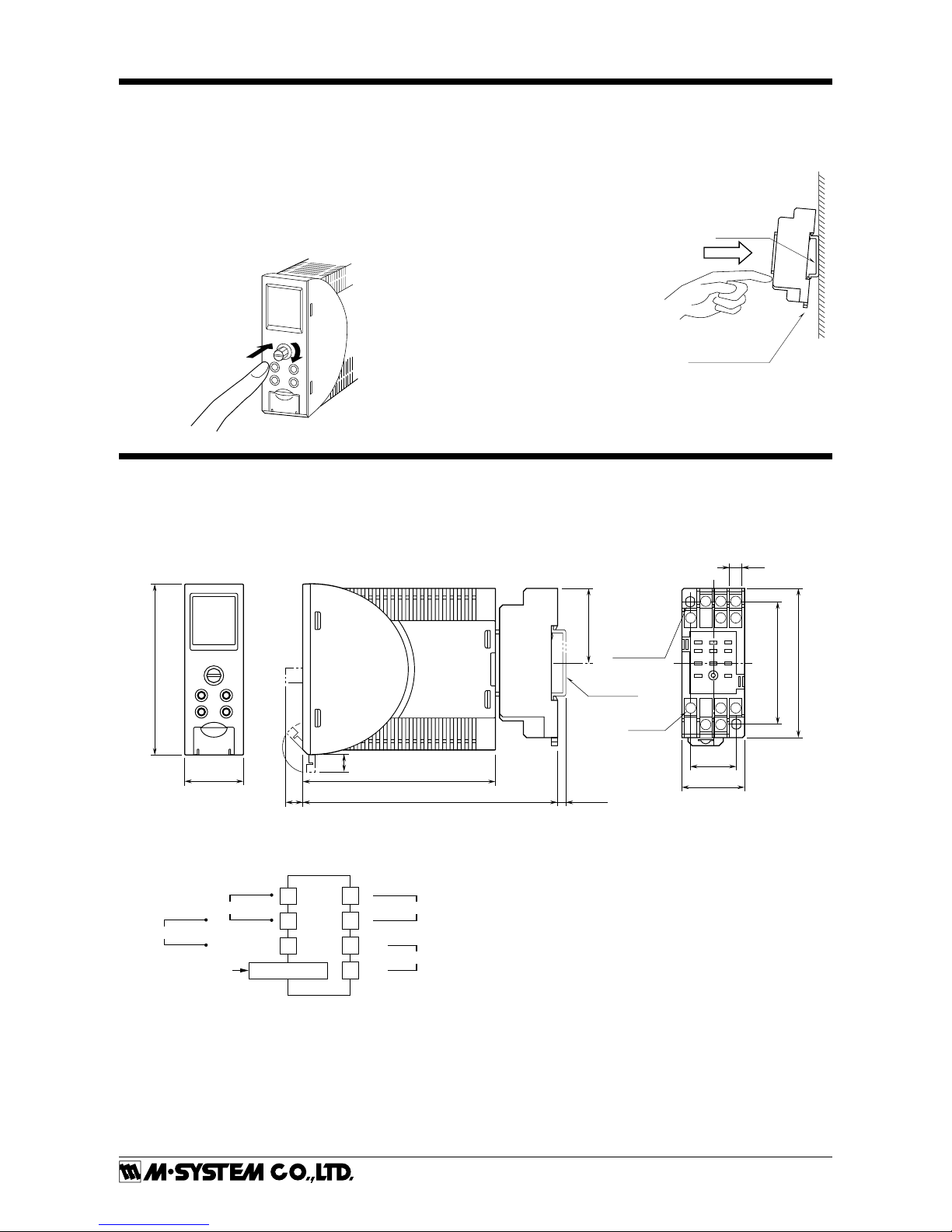
COMPONENT IDENTIFICATION
Connection Diagram
(Side)
Body
Base Socket
Display
Fixing Screw
(screw for attaching
the body to the socket)
Mode
Set
Up
Down
Specification
Page 2
M2EXV
5-2-55, Minamitsumori, Nishinari-ku, Osaka 557-0063 JAPAN
Phone: +81(6)6659-8201 Fax: +81(6)6659-8510 E-mail: info@m-system.co.jp
EM-5133-B Rev1 P. 2 / 18
INSTALLATION
Loosen the fixing screw in front of the unit in order to separate the body from the base socket.
■ FIXING SCREW
The fixing screw can be pushed into the body when it is
not in use. Tighten the knob until the body is securely attached to the base socket. Push it into the body and turn it
clockwise to lock. Push the knob and turn it counterclockwise to unlock so that the know pops out.
■
DIN Rail
35mm wide
Spring Loaded
DIN Rail Adaptor
DIN RAIL MOUNTING
Set the base socket so that
its DIN rail adaptor is at
the bottom. Position the
upper hook at the rear side
of base socket on the DIN
rail and push in the lower.
When removing the socket,
push down the DIN rail
adaptor utilizing a minus
screwdriver and pull.
■ WALL MOUNTING
Refer to the drawings in
the shown below.
TERMINAL CONNECTIONS
Connect the unit as in the diagram below or refer to the connection diagram on the side of the unit.
■ EXTERNAL DIMENSIONS unit: mm (inch)
28.5 (1.12)
83 (3.27)
94 (3.70)
8
(.31)
124 (4.88)
22 (.87)
6 (.23)
59 (2.32)
11–M3
SCREW
72 (2.83)
36 (1.42)
29.5 (1.16)
2–4.2x5
(.17x.20)
MTG HOLE
6 (.24) deep
DIN RAIL
35mm wide
[4 (.16)]
• When mounting, no extra space is needed between units.
4
8 7
10
8
(.31)
11
56
123
9
■ CONNECTION DIAGRAM
1
4
2
+
–
OUTPUT
7
8
10
11
CONFIGURATOR
JACK
U(+)
V(–)
POWER
–
Input Current
+
+
Input Voltage
–
Page 3
M2EXV
5-2-55, Minamitsumori, Nishinari-ku, Osaka 557-0063 JAPAN
Phone: +81(6)6659-8201 Fax: +81(6)6659-8510 E-mail: info@m-system.co.jp
EM-5133-B Rev1 P. 3 / 18
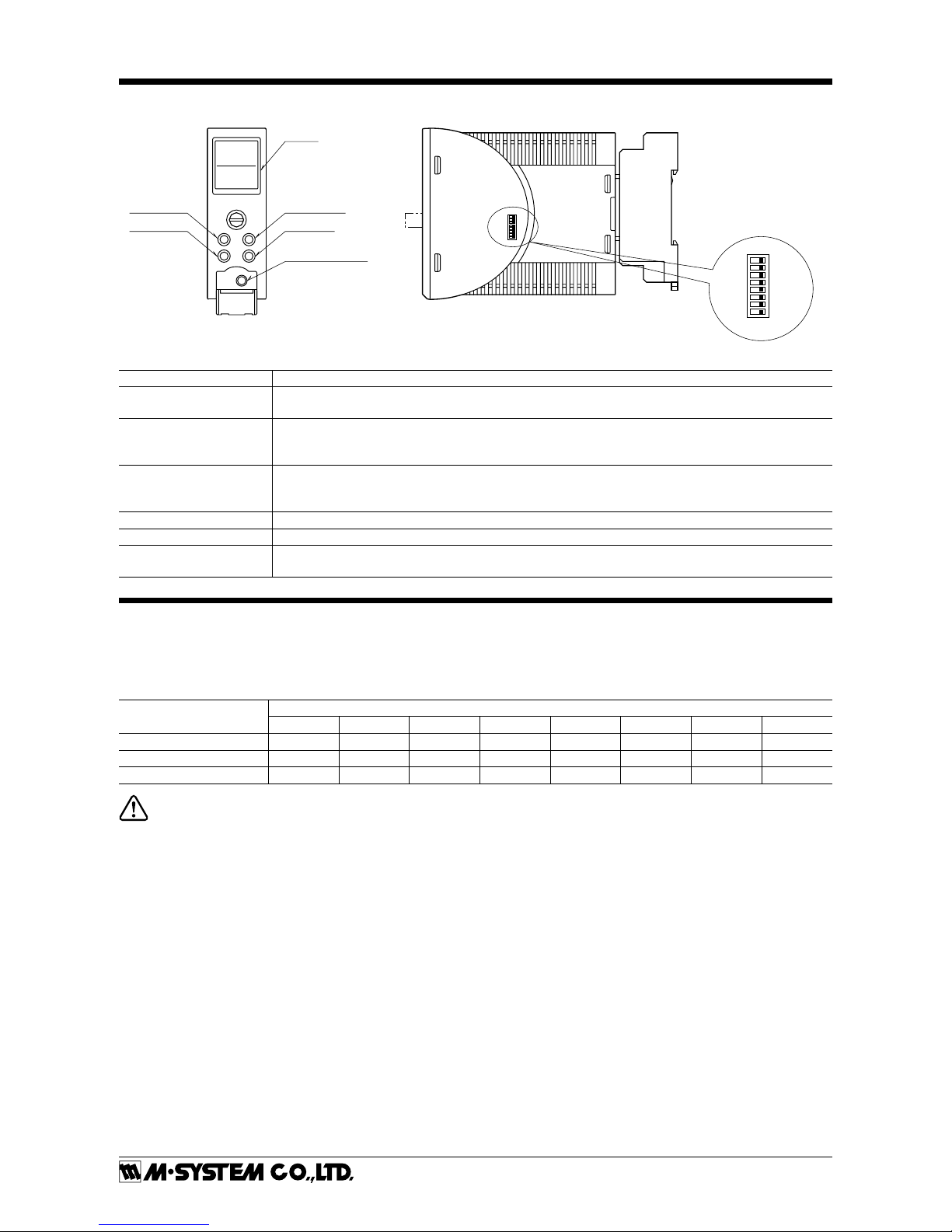
EXTERNAL VIEWS
Display
Mode Button
Set Button
Configurator Jack
Up Button
Down Button
Up
Down
Mode
Set
Output Setting DIP SW
ON
1
2
3
4
5
6
7
8
SW1
OFF
ON
1
2
3
4
5
6
7
8
SW1
OFF
PERCENT
100.00
OUTPUT
20.000
%
mA
COMPONENT FUNCTION
Display
Indicates present values, setting values and abnormal information. Two types of present values at upper and lower are displayed by setting.
Mode button
Used to shift from measuring mode to each setting mode. Destination to shift is changed by the time
pressing and holding the button. Used to return from each setting mode to measuring mode. (press and
hold for 2 sec. or more)
Set button
Used to change setting value of setting parameter. When at setting changeable state, used to enter
(save) the setting value. Used to move on through digits of setting value for input/output scaling at
setting changeable state,
Up button Used to shift through setting parameter, and to increase or select setting value.
Down button Used to shift through setting parameter, and to decrease or select setting value.
Configurator Jack Used to configure with M2E configurator software (model: M2ECFG). At the same time, set the lockout
setting of the unit to ‘lock’.
DIP SWITCH
The internal DIP switch for output setting is required to select output types before setting a precise output range using front
buttons or setting with a PC.
Refer to the “PROGRAMMING” for the operation with front buttons. Refer to the users manual (EM-5147) of M2E Configurator
Software (model: M2ECFG) for setting with PC.
Output Range
SW1
1 2 3 4 5 6 7 8
0 – 20mA OFF ON OFF OFF OFF OFF ON OFF
-5 – +5V OFF OFF ON OFF ON OFF OFF ON
-10 – +10V OFF OFF ON OFF OFF ON OFF ON
CAUTION: DO NOT set DIP switches while power is supplied. Otherwise, the unit may fail.
Page 4
M2EXV
5-2-55, Minamitsumori, Nishinari-ku, Osaka 557-0063 JAPAN
Phone: +81(6)6659-8201 Fax: +81(6)6659-8510 E-mail: info@m-system.co.jp
EM-5133-B Rev1 P. 4 / 18
SCREEN DISPLAY
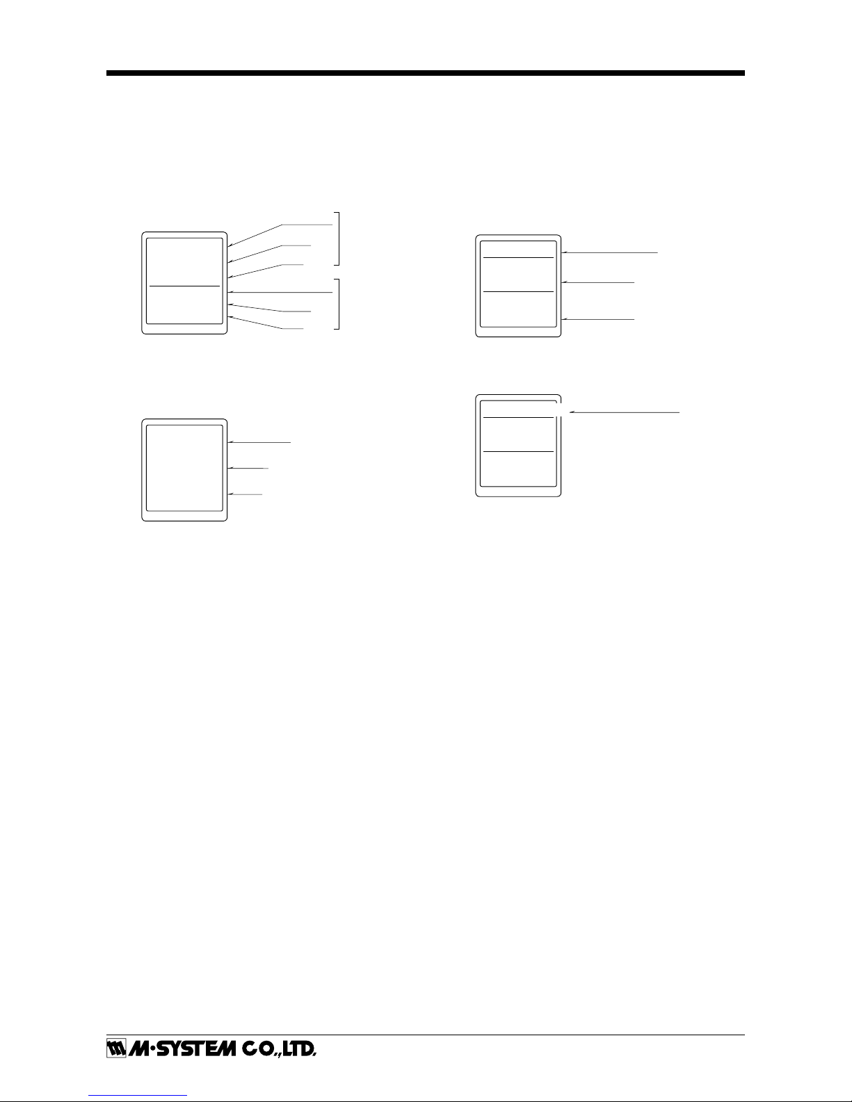
■ DISPLAY IN MEASURING MODE
• Double tiered display
The unit can select and display any two items out of input
engineering value, input scaling value, % value*, output engineering value, and output scaling value.
* Percent value for input.
INP (Scaling)
L /
min
12.34
50.00
PERCENT
%
Item name
Value
Unit
Item name
Value
Unit
Upper
Lower
• Single tiered display
When displayed item is one, it is available to show big characters in single tiered display.
INPUT
mA
20.00
Value
Unit
Item name
Refer to the Display setting of the Advanced mode for
settings.
■ DISPLAY IN EACH SETTING MODE
For each setting, current values of setting parameter, ITEM
number and setting value are indicated. During setting,
‘(Setting)’ is indicated at the side of ‘DATA’ display.
If the power is mistakenly shut down during setting, setting values are discarded. (Return to the value before setting change.) Setting display previously displayed before
power shutdown is indicated at next power up.
Input range
ITEM
11
DATA (Setting)
-10–+10V
Setting parameter
Item number
Setting Value
The long setting parameter is indicated by scrolling.
ITEM
14
DATA
0.00
Indicated by scrolling
0% input scaling
■ DISPLAY TIMEOUT
When there is no operation within the setting time of display timeout, display is turned off. Pressing Mode, Set, Up
or Down button or occurring error enables to return from
display off. Set ‘0’ to display ‘always on’.
Page 5
M2EXV
5-2-55, Minamitsumori, Nishinari-ku, Osaka 557-0063 JAPAN
Phone: +81(6)6659-8201 Fax: +81(6)6659-8510 E-mail: info@m-system.co.jp
EM-5133-B Rev1 P. 5 / 18
PROGRAMMING
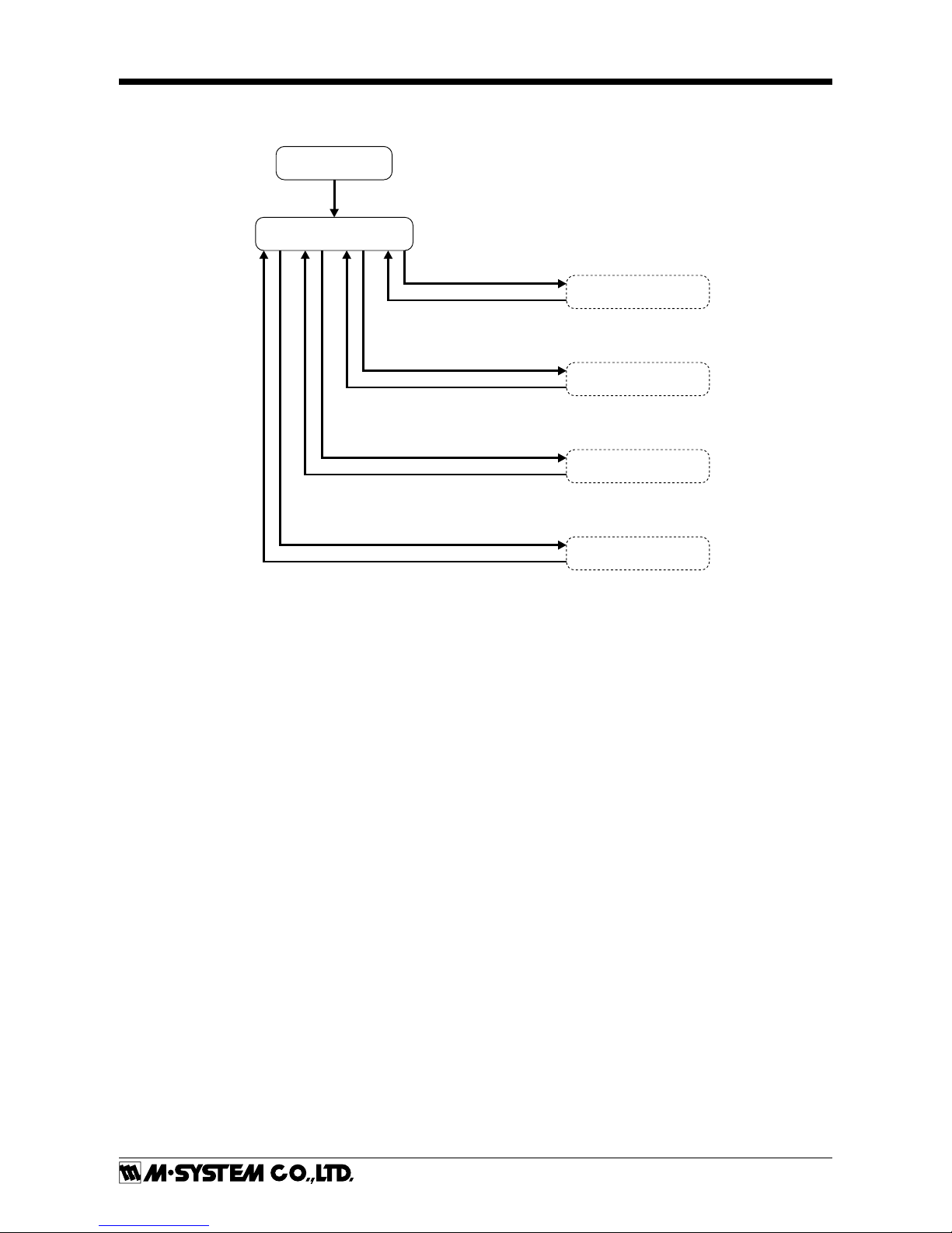
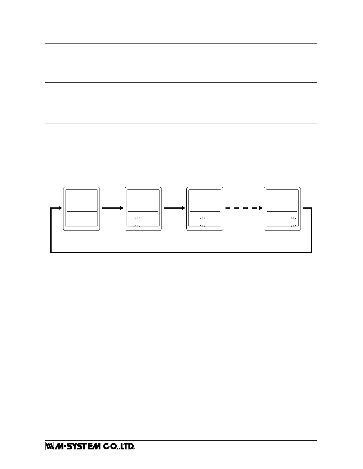
■ SETTING FLOWCHART
POWER ON
Measuring Mode
Hold down Mode button for ≥ 2 seconds
Hold down Mode button
for ≥ 2 seconds
Basic Setting Mode
Option Mode
Advanced Mode
Hold down Mode button for ≥ 2 seconds
Hold down Mode button for ≥ 4 seconds
Hold down Mode button for ≥ 2 seconds
Hold down Mode button for ≥ 6 seconds
Linearization Mode
Hold down Mode button for ≥ 2 seconds
Hold down Mode button for ≥ 8 seconds
Page 6
M2EXV
5-2-55, Minamitsumori, Nishinari-ku, Osaka 557-0063 JAPAN
Phone: +81(6)6659-8201 Fax: +81(6)6659-8510 E-mail: info@m-system.co.jp
EM-5133-B Rev1 P. 6 / 18
■ OPERATION IN EACH SETTING MODE
• Basic operation
Mode button: In measuring mode, holding down Mode button for ≥ 2 seconds, ≥ 4 seconds, ≥ 6 seconds or ≥ 8 seconds
enables to move on to each setting mode. Holding down Mode button for ≥ 2 seconds at each setting item
display enables to return to measuring mode.
Holding down Mode button for ≥ 2 seconds while changing settings (‘(Setting)’ is displayed next to ‘DATA’)
enables to discard setting value in changing, and to return to the state before change settings (‘(Setting)’
next to ‘DATA’ is off).
Set button: Pressing Set button at each setting parameter enables to blink setting value and changing settings is
ready (‘(Setting)’ is displayed next to ‘DATA’). Pressing Set button while changing settings enables to
save (enter) setting value and change from blinking to on.
Up button: Press Up button to move through setting parameters. Selecting setting value while changing settings,
increasing a setting value to set value. Keeping pressing Up button enables to increase the value
continuously.
Down button: Press Down button to move through setting parameters. Selecting setting value while changing settings,
decreasing a setting value to set value. Keeping pressing Down button enables to decrease the value
continuously.
• Input / output display scaling setting parameter
For input/output display scaling setting parameter, set values digit by digit. Pressing Set button enables to move blinking
digit. Adjust blinking digit to set numerical value with Up and Down button. Blinking digit moves from most significant digit
with pressing Set button. At least significant digit, pressing Set button again enables to turn on and determine the setting
value. During setting, press and hold Mode button for ≥ 2 seconds to discard the setting value.
ITEM
14
DATA
0
0% input scal
ITEM
14
DATA (Setting)
0% input scal
ITEM
14
DATA (Setting)
0% input scal
ITEM
14
DATA (Setting)
0% input scal
Set button Set button Set button
Setting sixth digit Setting fifth digit
Set button (save)
Setting first digit
000000 000000000000
• Lockout setting
‘Lockout setting’ is available for the unit. When unlocking the lockout setting, indicate ‘Lockout Setting’ of ‘ITEM01’ in each
setting mode and set ‘Unlock’. To enable lockout setting again, set ‘Lock’. Even when lockout setting is enabled, it is available to confirm the each setting value. ‘DATA (Locked)’ is indicated in that case.
Page 7

M2EXV
5-2-55, Minamitsumori, Nishinari-ku, Osaka 557-0063 JAPAN
Phone: +81(6)6659-8201 Fax: +81(6)6659-8510 E-mail: info@m-system.co.jp
EM-5133-B Rev1 P. 7 / 18
■ BASIC SETTING MODE
Measuring Mode
Lockout Setting
Input Range
0% Input Setting
100% Input Setting
0% Input Scaling
100% Input Scaling
Input Decimal Point
Output Range
0% Output Setting
100% Output Setting
0% Output Scaling
100% Output Scaling
Output Decimal Point
Loop Test
Set
Set
Hold down Mode button
for ≥ 2 seconds
Hold down Mode button
for ≥ 2 seconds
Set
Set
Set
Set
Set
Set
Set
Set
Set
Set
Set
Set
Set
SetSet
Set
Set
Set
Set
Set
Set
Set
Set
Set
Set
Set
Set
Up Down
Up Down
Up Down
Up Down
Up Down
Up Down
Up Down
Up Down
Up Down
Up Down
Up Down
Up Down
Up Down
Up Down
Lock / Unlock
0 – 50 mA /
-1000 – +1000 mV /
-10 – +10 V
0.00 – 48.00 /
-1000.0 – 900.0 /
-10.000 – 9.000
2.00 – 50.00 /
-900.0 – 1000.0 /
-9.000 – 10.000
-99999 – 999999
-99999 – 999999
oooooo / ooooo.o
oooo.oo / ooo.ooo
oo.oooo / o.ooooo
0 – 20 mA /
-5 – +5 V /
-10 – +10 V
0.000 – 19.000 /
-5.000 – 4.750 /
-10.000 – 9.000
1.000 – 20.000 /
-4.750 – 5.000 /
-9.000 – 10.000
-99999 – 999999
-99999 – 999999
oooooo / ooooo.o
oooo.oo / ooo.ooo
oo.oooo / o.ooooo
Cancel / Set
Basic Setting Mode
Page 8

M2EXV
5-2-55, Minamitsumori, Nishinari-ku, Osaka 557-0063 JAPAN
Phone: +81(6)6659-8201 Fax: +81(6)6659-8510 E-mail: info@m-system.co.jp
EM-5133-B Rev1 P. 8 / 18
• Parameters
MODE ITEM SETTING PARAMETER RANGE UNIT INITIAL VALUE
Basic setting 01 Lockout setting Lock / Unlock — Lock
11
Input range 0 – 50mA
-1000 – +1000mV
-10 – +10V
— 0 – 50mA
12
0 % input setting 0.00 – 48.00
-1000.0 – 900.0
-10.000 – 9.000
mA
mV
V
4.00
13
100 % input setting 2.00 – 50.00
-900.0 – 1000.0
-9.000 – 10.000
mA
mV
V
20.00
14 0 % input scaling -99999 – 999999 — 0.00
15 100 % input scaling -99999 – 999999 — 100.00
16
Input decimal point No decimal point
The number of decimal
places : 1 – 5,
— 2 places of decimals
17
Output range 0 – 20mA
-5 – +5V
-10 – +10V
— 0 – 20mA
18
0 % output setting 0.000 – 19.000
-5.000 – 4.750
-10.000 – 9.000
mA
V
V
4.000
19
100 % output setting 1.000 – 20.000
-4.750 – 5.000
-9.000 – 10.000
mA
V
V
20.000
20 0 % output scaling -99999 – 999999 — 0.00
21 100 % output scaling -99999 – 999999 — 100.00
22
Output decimal point No decimal point
The number of decimal
places : 1 – 5,
— 2 places of decimals
26 Loop test -5.00 – 105.00 % Cancel
Page 9

M2EXV
5-2-55, Minamitsumori, Nishinari-ku, Osaka 557-0063 JAPAN
Phone: +81(6)6659-8201 Fax: +81(6)6659-8510 E-mail: info@m-system.co.jp
EM-5133-B Rev1 P. 9 / 18
[01] Lockout Setting
Set Lock / Unlock of lockout setting.
SETTING VALUE DESCRIPTION INITIAL VALUE
Lock Lockout setting enable
Lock
Unlock Lockout setting disable
Even when setting is ‘Lock’, it is available to move on to
each setting mode and confirm the setting value of each
setting parameter. In each setting parameter display, when
‘Lock’, ‘DATA (Locked)’ is indicated, when ‘Unlock’, ‘DATA’
is indicated.
[11] Input range
Set the type of output signal
SETTING VALUE DESCRIPTION INITIAL VALUE
0 – 50 mA
Input: 0 – 50 mA DC
0 – 50 mA-1000 – +1000 mV
Input: -1000 – +1000 mV DC
-10 – +10 V
Input: -10 – +10 V DC
When input range is changed, turn the power off, and change
the connection to the input terminal of the unit. Input setting value is changed to initial value.
[12] 0 % input setting
Set the 0 % input setting.
Setting range differs according to input range.
INPUT RANGE
SETTING RANGE
MIN. SPAN
INITIAL VALUE
0 – 50 mA 0.00 – 48.00 2.00 4.00
-1000 – +1000 mV -1000.0 – 900.0 100.0 -1000.0
-10 – +10 V -10.000 – 9.000 1.000 -10.000
Set as follows.
[12] 0 % input setting < [13] 100 % input setting
[13] 100 % input setting
Set the 100 % input setting.
Setting range differs according to input range.
INPUT RANGE
SETTING RANGE
MIN. SPAN
INITIAL VALUE
0 – 50 mA 2.00 – 50.00 2.00 20.00
-1000 – +1000 mV -900.0 – 1000.0 100.0 1000.0
-10 – +10 V -9.000 – 10.000 1.000 10.000
Set as follows.
[12] 0 % input setting < [13] 100 % input setting
[14] 0 % input scaling
Set the display value of 0 % input setting.
SETTING RANGE INITIAL VALUE
-99999 – 999999 0.00
[15] 100 % input scaling
Set the display value of 100 % input setting.
SETTING RANGE INITIAL VALUE
-99999 – 999999 100.00
[16] Input decimal point
Set the decimal point position of [14] 0 % and [15] 100 %
input display scaling.
SETTING VALUE
DESCRIPTION INITIAL VALUE
oooooo Decimal point: None
2 places of
decimals
ooooo.o Number of decimal places: 1
oooo.oo Number of decimal places: 2
ooo.ooo Number of decimal places: 3
oo.oooo Number of decimal places: 4
o.ooooo Number of decimal places: 5
[17] Output range
Set the range of output signal of the unit.
SETTING VALUE DESCRIPTION INITIAL VALUE
0 – 20 mA Output: 0 – 20 mA DC
0 – 20 mA-5 – +5 V Output: -5 – +5 V DC
-10 – +10 V Output: -10 – +10 V DC
When output range is changed, turn the power off, and
then set the output setting DIP SW on the side of the unit.
Setting is as follows. Output setting value is changed to initial value.
OUTPUT
RANGE
SW1
1 2 3 4 5 6 7 8
0 – 20 mA OFF ON OFF OFF OFF OFF ON OFF
-5 – +5 V
OFF OFF ON OFF ON OFF OFF ON
-10 – +10 V
OFF OFF ON OFF OFF ON OFF ON
[18] 0 % output setting
Set the 0 % output setting.
OUTPUT RANGE
SETTING RANGE
MIN. SPAN
INITIAL VALUE
0 – 20 mA 0.000 – 19.000 1.000 4.000
-5 – +5 V -5.000 – 4.750 0.250 -5.000
-10 – +10 V -10.000 – 9.000 1.000 -10.000
Set as follows.
[18] 0 % output setting < [19] 100 % output setting
The value is indicated by ‘OUTPUT’ at measuring mode.
[19] 100 % output setting
Set the 100 % output setting.
OUTPUT RANGE
SETTING RANGE
MIN. SPAN
INITIAL VALUE
0 – 20 mA 1.000 – 20.000 1.000 20.000
-5 – +5 V -4.750 – 5.000 0.250 5.000
-10 – +10 V -9.000 – 10.000 1.000 10.000
Set as follows.
[18] 0 % output setting < [19] 100 % output setting
The value is indicated by ‘OUTPUT’ at measuring mode.
[20] 0 % output scaling
Set the display value of [18] 0 % output setting.
SETTING RANGE INITIAL VALUE
-99999 – 999999 0.00
[21] 100 % output scaling
Set the display value of [19] 100 % output setting.
SETTING RANGE INITIAL VALUE
-99999 – 999999 100.00
Page 10

M2EXV
5-2-55, Minamitsumori, Nishinari-ku, Osaka 557-0063 JAPAN
Phone: +81(6)6659-8201 Fax: +81(6)6659-8510 E-mail: info@m-system.co.jp
EM-5133-B Rev1 P. 10 / 18
[22] Output decimal point
Set decimal point position for [20] 0 % and [21] 100 % output scaling.
SETTING VALUE DESCRIPTION INITIAL VALUE
oooooo Decimal point: None
2 places of
decimals
ooooo.o Number of decimal places: 1
oooo.oo Number of decimal places: 2
ooo.ooo Number of decimal places: 3
oo.oooo Number of decimal places: 4
o.ooooo Number of decimal places: 5
[26] Loop test
As pressing Set button enables to blink ‘Cancel’, changing to ‘Set’ by pressing Up or Down and pressing ‘Set’ allows to indicate
Loop Test display. Present value is indicated. Increase or decrease it by pressing Up and Down button. Press and hold them
enables to change value continuously.*
1
Pressing and holding Mode button more than 2 seconds or turning off the power enable to exit loop test.
ITEM
26
Loop test
ITEM
26
DATA (Setting) DATA (Setting)
Loop test Loop test
Up/Down
button
Set button
Set
mA
4.000
0.00
%
Cancel
Output engineering value
Output % value
*1. While loop test is performing, actual input is disregarded.
While loop test is performing and ‘Display timeout’ is enabled to display off, return to the display on by pressing a front button.
Page 11

M2EXV
5-2-55, Minamitsumori, Nishinari-ku, Osaka 557-0063 JAPAN
Phone: +81(6)6659-8201 Fax: +81(6)6659-8510 E-mail: info@m-system.co.jp
EM-5133-B Rev1 P. 11 / 18
■ OPTION MODE
Measuring Mode
Unit (INP Scaling)
Unit (OUT Scaling)
Filter time constant
Input Zero fine adjust
Input Span fine adjust
Output Zero fine adjust
Output Span fine adjust
Lockout setting
*1. Refer to [60] Unit (INP Scaling) or [61] Unit (OUT Scaling) for usable unit.
Set
Set
Hold down Mode button
for ≥ 4 seconds
Hold down Mode button
for ≥ 2 seconds
Set
Set
Set
Set
Set
Set
Set
Set
Set
Set
Set
Set
Set
SetSet
Up Down
Up Down
Up Down
Up Down
Up Down
Up Down
Up Down
Up Down
*1
*1
0 – 30
-5.000 – 5.000
95.000 – 105.000
-5.000 – 5.000
95.000 – 105.000
Lock / Unlock
Option Mode
• Parameters
MODE ITEM SETTING PARAMETER RANGE UNIT INITIAL VALUE
Option 60 Unit (INP Scaling) Choose from 68 types — %
61 Unit (OUT Scaling) Choose from 68 types — %
67 Filter time constant 0 – 30 sec. 0
69 Input Zero fine adjust -5.000 – 5.000 % 0.000
70 Input Span fine adjust 95.000 – 105.000 % 100.000
71 Output Zero fine adjust -5.000 – 5.000 % 0.000
72 Output Span fine adjust 95.000 – 105.000 % 100.000
01 Lockout setting Lock / Unlock — Lock
Page 12

M2EXV
5-2-55, Minamitsumori, Nishinari-ku, Osaka 557-0063 JAPAN
Phone: +81(6)6659-8201 Fax: +81(6)6659-8510 E-mail: info@m-system.co.jp
EM-5133-B Rev1 P. 12 / 18
[60] Unit (INP Scaling)
Set the unit to display input scaling.
Available units are following 68 types.
DC, AC, mV, V, kV, μA, mA, A, kA, mW, W, kW, var, kvar,
Mvar, VA, Hz, Ω, kΩ, MΩ, cm, mm, m, m/sec, mm/min,
cm/min, m/min, m/h, m/s
2
, inch, L, L/s, L/min, L/h, m3,
m
3
/sec, m3/min, m3/h, Nm3/h, N∙m, N/m2, g, kg, kg/h, N, kN,
Pa, kPa, Mpa, t, t/h, °C, °F, K, %RH, J, kJ, MJ, rpm, sec, min,
min
-1
, pH, %, ppm, deg, (blank), User
Selecting ‘User’ enables to move on to user’s unit setting
display. A unit can be created by using any characters. Up
to 13 characters available.
*1
Up and Down button enables
to move on selected characters. Set button enables to select
a character. While setting, pressing Mode button enables to
delete a character, pressing and holding Mode button enables to discard the settings. Pressing and holding Set button enables to determine the setting and return to setting
display of [60] Unit (INP Scaling). The unit is indicated by
‘INPUT (Scaling)’ at measuring mode display.
If turning power off while setting, it returns to setting
display of [60] Unit (INP Scaling). (The setting value is
discarded.)
*1. Settable characters
0 − 9 A − Z a − z !
”
# $ % &
’ ( ) = - + * ^
| @ ` [ ] { } ; : < > ? _ , . /
Initial value: %
[61] Unit (OUT Scaling)
Set the unit to display output scaling.
Available units are following 68 types.
DC, AC, mV, V, kV, μA, mA, A, kA, mW, W, kW, var, kvar,
Mvar, VA, Hz, Ω, kΩ, MΩ, cm, mm, m, m/sec, mm/min,
cm/min, m/min, m/h, m/s
2
, inch, L, L/s, L/min, L/h, m3,
m
3
/sec, m3/min, m3/h, Nm3/h, N∙m, N/m2, g, kg, kg/h, N, kN,
Pa, kPa, Mpa, t, t/h, °C, °F, K, %RH, J, kJ, MJ, rpm, sec, min,
min
-1
, pH, %, ppm, deg, (blank), User
Selecting ‘User’ enables to move on to user’s unit setting
display. A unit can be created by using any characters. Up
to 13 characters available.
*1
Up and Down button enables
to move on selected characters. Set button enables to select
a character. While setting, pressing Mode button enables to
delete a character, pressing and holding Mode button enables to discard the settings. Pressing and holding Set button enables to determine the setting and return to setting
display of [61] Unit (OUT Scaling). The unit is indicated by
‘OUTPUT (Scaling)’ at measuring mode display.
If turning power off while setting, it returns to setting
display of [61] Unit (OUT Scaling). (The setting value is
discarded.)
*1. Settable characters
0 − 9 A − Z a − z ! ” # $ % &
’ ( ) = - + * ^
| @ ` [ ] { } ; : < > ? _ , . /
Initial value: %
[67] Filter time constant
Set filter time constant of the first order lag filter.
The first order lag filter is available with setting time.
When ‘0’ is set to this parameter, the first order lag filter is
not available. (Response time: ≤ 0.5 sec. (0 ➝ 90 %))
The first order lag filter is equivalent to general CR filter.
The setting time constant is the time to follow until about
63 %, when input varies from 0 % to 100 %.
It is available to set the range between 0 – 30 seconds.
Initial value: 0
[69] Input Zero ne adjust
Perform fine adjustment of input signal. Available range
between −5.000 – +5.000 %.
Initial value: 0.000
[70] Input Span ne adjust
Perform fine adjustment of input signal. Available range
between 95.000 – 105.000 %.
Initial value: 100.000
[71] Output Zero ne adjust
Perform fine adjustment of output signal. Available range
between −5.000 – +5.000 %.
Initial value: 0.000
[72] Output Span ne adjust
Perform fine adjustment of output signal. Available range
between 95.000 – 105.000 %.
Initial value: 100.000
[01] Lockout Setting
Set Lock / Unlock of lockout setting.
SETTING VALUE DESCRIPTION INITIAL VALUE
Lock Lockout setting enable
Lock
Unlock Lockout setting disable
Even when setting is ‘Lock’, it is available to move on to
each setting mode and confirm the setting value of each
setting parameter. In each setting parameter display, when
‘Lock’, ‘DATA (Locked)’ is indicated, when ‘Unlock’, ‘DATA’
is indicated.
Page 13

M2EXV
5-2-55, Minamitsumori, Nishinari-ku, Osaka 557-0063 JAPAN
Phone: +81(6)6659-8201 Fax: +81(6)6659-8510 E-mail: info@m-system.co.jp
EM-5133-B Rev1 P. 13 / 18
■ ADVANCED MODE
Measuring Mode
Display setting
Brightness
Display timeout
Reset all settings
Version indication
Lockout setting
*1. For detail, refer to the Display Setting.
Set
Set
Hold down Mode button
for ≥ 6 seconds
Hold down Mode button
for ≥ 2 seconds
Set
Set
Set
Set
Set
Set
Set
Set
Up Down
Up Down
Up Down
Up Down
Up Down
Up Down
*1
1 – 4
0, 1 – 60
OFF / RESET
Lock / Unlock
Advanced Mode
• Parameters
MODE ITEM SETTING PARAMETER RANGE UNIT INITIAL VALUE
Advanced
90
Display setting Upper: choose from 5 types
Lower: choose from 6 types
— Upper: INPUT
Lower: PERCENT
91 Brightness 1 (darkest) – 4 (brightest) — 4
92 Display timeout 0 (always on), 1 – 60 min. 10
93 Reset all settings OFF / RESET — OFF
94 Version indication — — —
01 Lockout setting Lock / Unlock — Lock
Page 14

M2EXV
5-2-55, Minamitsumori, Nishinari-ku, Osaka 557-0063 JAPAN
Phone: +81(6)6659-8201 Fax: +81(6)6659-8510 E-mail: info@m-system.co.jp
EM-5133-B Rev1 P. 14 / 18
[90] Display setting
Set display setting in measuring mode. Display is divided, indicating item can be set for each upper and lower.
Pressing Set button once is setting for upper, pressing again
for lower, pressing once more for setting determined.
Upper
SETTING VALUE DESCRIPTION
INITIAL VALUE
INPUT
Input engineering unit value
INPUT
(engineering
value)
INPUT (Scaling)
*1
Input scaling
PERCENT Percent value
*3
OUTPUT
Output engineering unit value
OUTPUT (Scaling)*2Output scaling
*1. Display at measuring mode is INP (Scaling).
*2. Display at measuring mode is OUT (Scaling).
*3. Input percent value.
Lower
SETTING VALUE DESCRIPTION
INITIAL VALUE
INPUT
Input engineering unit value
PERCENT
(
percent value
)
*3
INPUT (Scaling)*1Input scaling
PERCENT Percent value
*3
OUTPUT
Output engineering unit value
OUTPUT (Scaling)*2Output scaling
None No display
*1. Display at measuring mode is INP (Scaling).
*2. Display at measuring mode is OUT (Scaling).
*3. Input percent value.
[91] Brightness
Adjust brightness of display. It is available to set the range
between 1 (darkest) – 4 (brightest).
Initial value: 4
[92] Display timeout
Set the time to off the display when there is no operation
within a certain time.
It is available to set the range between 0 – 60 minutes.
Set ‘0’ to display ‘always on’.
When error is occured at display off, the display returns
from off.
Initial value: 10
[93] Reset all settings
Return settings to initial value.
SETTING VALUE DESCRIPTION
OFF Not initialized.
RESET Initialize all settings.
*1
*1. When setting value is initialized, each parameters cur-
rently set are over written by initial value. ‘COMPLETE’ is
indicated when initializing setting value is completed. Notice that it does not return to the setting value, which is
specified by the option Ex-factory setting (/SET). Configure
initialized value again with DIP switch with power off for
output setting.
[94] Version indication
Indicate firmware version.
[01] Lockout Setting
Set Lock / Unlock of lockout setting.
SETTING VALUE DESCRIPTION INITIAL VALUE
Lock Lockout setting enable
Lock
Unlock Lockout setting disable
Even when setting is ‘Lock’, it is available to move on to
each setting mode and confirm the setting value of each
setting parameter. In each setting parameter display, when
‘Lock’, ‘DATA (Locked)’ is indicated, when ‘Unlock’, ‘DATA’
is indicated.
Page 15

M2EXV
5-2-55, Minamitsumori, Nishinari-ku, Osaka 557-0063 JAPAN
Phone: +81(6)6659-8201 Fax: +81(6)6659-8510 E-mail: info@m-system.co.jp
EM-5133-B Rev1 P. 15 / 18
■ LINEARIZATION MODE
Measuring Mode
User's table linearization
Number of points
Ta ble
X001
Ta ble
Y001
Ta ble
X002
Ta ble
Y002
Lockout setting
Set
When Linearization is enabled.
Set
Hold down Mode button
for ≥ 8 seconds
Hold down Mode button
for ≥ 2 seconds
Set
Set
Set
Set
Set
Set
Set
Set
Set
Set
Set
SetSet
Up Down
Up Down
Up Down
Up Down
Up Down
Up Down
Up Down
Up Down
Disable / Enable
2 – 111
-5.00 – 105.00
-5.00 – 105.00
-5.00 – 105.00
-5.00 – 105.00
Lock / Unlock
Linearization Mode
• Parameters
MODE ITEM SETTING PARAMETER RANGE UNIT INITIAL VALUE
Linearization 100 User's table linearization Disable / Enable — Disable
166 Number of points 2 – 111 — 2
167 –
388
Table -5.00 – 105.00 % X001 -5.00
Y001 -5.00
X002 105.00
Y002 105.00
01 Lockout setting Lock / Unlock — Lock
Page 16

M2EXV
5-2-55, Minamitsumori, Nishinari-ku, Osaka 557-0063 JAPAN
Phone: +81(6)6659-8201 Fax: +81(6)6659-8510 E-mail: info@m-system.co.jp
EM-5133-B Rev1 P. 16 / 18
[100] User’s table linearization
SETTING VALUE DESCRIPTION INITIAL VALUE
Disable Linearization disable
Disable
Enable Linearization enable
When Enable is selected, input is converted to output by
using user’s table.
[166] Number of points
Set number of points for user’s table.
It is available to set the range between 2 – 111 points.
Initial value: 2
[167 – 388] Table
For the conversion by using user’s table, conversion input
is searched from the table in which X corresponds to input
(unit: %) and Y corresponds to output (unit: %) are paired,
and Y, which corresponds output of matched table, is the
output.
The range is available between -5 to +105 (%) for both X and
Y. For X, it is required to set in ascending order from X001.
Be sure that if it is set with other than ascending order, correct conversion is not carried out.
Initial value: X001 -5.00
Y001 -5.00
X002 105.00
Y002 105.00
E.g. Setting ascending order
X001
105%
105%
-5%
Y005
Input %
Output %
Y004
Y003
Y002
Y001
-5%
X003 X002
X004 X005
When the input is not defined in the user’s table, two nearest value for each positive and negative are selected in written X. These two data are linearly interpolated and Y is
obtained and output it.
Xn Xn+1
Yn
Yn+1
Input %
Output %
[01] Lockout Setting
Set Lock / Unlock of lockout setting.
SETTING VALUE DESCRIPTION INITIAL VALUE
Lock Lockout setting enable
Lock
Unlock Lockout setting disable
Even when setting is ‘Lock’, it is available to move on to
each setting mode and confirm the setting value of each
setting parameter. In each setting parameter display, when
‘Lock’, ‘DATA (Locked)’ is indicated, when ‘Unlock’, ‘DATA’
is indicated.
Page 17

M2EXV
5-2-55, Minamitsumori, Nishinari-ku, Osaka 557-0063 JAPAN
Phone: +81(6)6659-8201 Fax: +81(6)6659-8510 E-mail: info@m-system.co.jp
EM-5133-B Rev1 P. 17 / 18
ERROR MESSAGES
DISPLAY ERROR DESCRIPTION WHAT TO DO
OVER RANGE U The input exceeds 105 %. Return the input signal not exceed 105 %.
OVER RANGE D The input exceeds lower limit of -5 %. Return the input signal -5 % or more.
SCALING ERROR U Input or output scaling value exceeds
999999 (upward).
Return the input or output signal not exceed 999999.
SCALING ERROR D Input or output scaling value exceeds
-99999 (downward).
Return the input or output signal not lower than -99999.
EEPROM I ERROR Internal data error Repair is needed if the display does not recover after the pow-
er is reset.
EEPROM R ERROR Memory reading error ‘Reset all settings’ in advanced mode.
*1
EEPROM W ERROR Memory writing error ‘Reset all settings’ in advanced mode.
*1
*1. All setting parameters are initialized. Repair is needed if it does not recover.
Indicated errors vary as follows depending on setting value of display settng.
Error is indicated blinking at upper or lower.
When multiple error occurs, only high priority error is displayed.
Order of priority is EEPROM ERROR, OVER RANGE, SCALING ERROR in descending order.
ERROR MESSAGES
DISPLAY SETTING
INPUT ENGINEERING
UNIT VALUE
INPUT SCALING
VALUE
PERCENT VALUE OUTPUT ENGINEERING
UNIT VALUE
OUTPUT SCALING
VALUE
OVER RANGE U
—
OVER RANGE D
SCALING ERROR U
(INPUT)
— — —
SCALING ERROR D
(INPUT)
SCALING ERROR U
(OUTPUT)
— — —
SCALING ERROR D
(OUTPUT)
EEPROM I ERROR
EEPROM R ERROR
EEPROM W ERROR
WIRING INSTRUCTIONS
■ SCREW TERMINAL
Torque: 0.8 N·m
■ SOLDERLESS TERMINAL
Refer to the drawing below for recommended ring tongue
terminal size. Spade tongue type is also applicable.
Applicable wire size 0.25 to 1.65 mm2 (AWG 22 to 16)
Recommended manufacturer: Japan Solderless Terminal
MFG.Co.Ltd, Nichifu Co.,ltd
6 (.24) max
3.3 (.13) max
mm (inch)
CHECKING
1) Terminal wiring: Check that all cables are correctly connected according to the connection diagram.
2) Check DIP switch setting.
3) Power input voltage: Check voltage across the terminal
10 – 11 with a multimeter.
4) Input: Check that the input signal is within 0 – 100% of
the full-scale.
5) Output: Check that the load resistance meets the described specifications.
Page 18

M2EXV
5-2-55, Minamitsumori, Nishinari-ku, Osaka 557-0063 JAPAN
Phone: +81(6)6659-8201 Fax: +81(6)6659-8510 E-mail: info@m-system.co.jp
EM-5133-B Rev1 P. 18 / 18
MAINTENANCE
Regular calibration procedure is explained below:
■ CALIBRATION
Without linearization, warm up the unit for at least 10
minutes. Apply 0%, 25%, 50%, 75% and 100% input signal.
Check that the output
signal for the respective input signal remains within accuracy described in the data sheet. If the output signal is out
of accuracy, when the input display value is out of accuracy,
perform the input fine adjustment. When the input display
value is correct but the output is out of accuracy, perform
the output fine adjustment. Refer to this manual, when
adjusting with front buttons. Refer to the M2ECFG users
manual (EM-5147), when adjusting with M2E Configurator
Software (model: M2ECFG). And then follow the procedure
shown below.
• INPUT FINE ADJUSTMENT
1) Set the input signal to 0 %, and adjust the input display
to 0 % by [69] Input Zero fine adjust.
2) Set the input signal to 100 %, and adjust the input display to 100 % by [70] Input Span fine adjust.
3) Again set the simulated input to 0 %, confirm the input
display.
4) If input display is shifted, repeat the procedure from 1)
to 3).
• OUTPUT FINE ADJUSTMENT
1) Set the simulated input to 0 %, and adjust the output
signal to 0 % by [71] Output Zero fine adjust.
2) Set the simulated input to 100 %, and adjust the output
signal to 100 % by [72] Output Span fine adjust.
3) Again set the simulated input to 0 %, confirm the output
signal.
4) If output signal is shifted, repeat the procedure from 1)
to 3).
LIGHTNING SURGE PROTECTION
M-System offers a series of lightning surge protector for
protection against induced lightning surges. Please contact
M-System to choose appropriate models.
 Loading...