

Page 1
M2EXV
5-2-55, Minamitsumori, Nishinari-ku, Osaka 557-0063 JAPAN
Phone: +81(6)6659-8201 Fax: +81(6)6659-8510 E-mail: info@m-system.co.jp
EM-5133-A Rev.1 P. 1 / 4
SIGNAL TRANSMITTER
(
PC programmable
)
MODEL
M2EXV
INSTRUCTION MANUAL
BEFORE USE ....
Thank you for choosing M-System. Before use, please check
contents of the package you received as outlined below.
If you have any problems or questions with the product,
please contact M-System’s Sales Office or representatives.
■ PACKAGE INCLUDES:
Signal conditioner (body + base socket) .............................(1)
■ MODEL NO.
Confirm Model No. marking on the side of the product to be
exactly what you ordered.
■ INSTRUCTION MANUAL
This manual describes necessary points of caution when
you use this product, including installation, connection and
detailed operation regarding settings. For detailed explanations, please refer to the Model M2EXV operating manual
(EM-5133-B).
The M2EXV is programmable using a PC. For detailed information on the PC configuration, refer to the M2ECFG
users manual (EM-5147).
The M2ECFG Configurator Software and the operating
manual (EM-5133-B) are downloadable at M-System’s web
site: http://www.m-system.co.jp
POINTS OF CAUTION
■ CONFORMITY WITH EU DIRECTIVES
•This equipment is suitable for Pollution Degree 2 and Installation Category II. Reinforced insulation (signal input or output to power input: 300V) and basic insulation
(signal input to output: 300V) are maintained. Prior to
installation, check that the insulation class of this unit
satisfies the system requirements.
•Altitude up to 2000 meters.
•The equipment must be mounted inside a panel.
•The equipment must be installed such that appropriate
clearance and creepage distances are maintained to conform to CE requirements. Failure to observe these requirements may invalidate the CE conformance.
•The actual installation environments such as panel configurations, connected devices, connected wires, may affect the protection level of this unit when it is integrated
in a panel system. The user may have to review the CE
requirements in regard to the whole system and employ
additional protective measures to ensure the CE conformity.
•Install lightning surge protectors for those wires connected to remote locations.
■ POWER INPUT RATING & OPERATIONAL RANGE
Locate the power input rating marked on the product and
confirm its operational range as indicated below:
100 – 240V AC rating: 85 – 264V, 47 – 66 Hz,
≤ 4.5VA at 100V AC
≤ 6.5VA at 200V AC
≤ 8.5VA at 264V AC
24V DC rating: 24V ±10%, ≤ 2.3W
110V DC rating: 85 – 150V, ≤ 2.3W
■ GENERAL PRECAUTIONS
Before you remove the unit from the socket or mount it,
turn off the power supply and input signal for safety.
■ ENVIRONMENT
•Indoor use
•When heavy dust or metal particles are present in the
air, install the unit inside proper housing with sufficient
ventilation.
•Do not install the unit where it is subjected to continuous
vibration. Do not subject the unit to physical impact.
•Environmental temperature must be within -5 to +55°C
(23 to 131°F) with relative humidity within 10 to 85% RH
in order to ensure adequate life span and operation.
■ WIRING
•Do not install cables close to noise sources (relay drive
cable, high frequency line, etc.).
•Do not bind these cables together with those in which
noises are present. Do not install them in the same duct.
■ AND ....
•The unit is designed to function as soon as power is supplied, however, a warm up for 10 minutes is required for
satisfying complete performance described in the data
sheet.
•With voltage output, do not leave the output terminals
shortcircuited for a long time. The unit is designed to endure it without breakdown, however, it may shorten appropriate life duration.
•The edge of the display may be hidden by the frame and
invisible depending on the view angle.
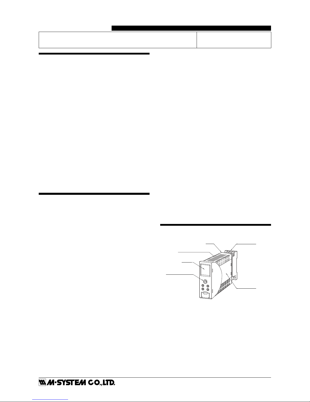
COMPONENT IDENTIFICATION
Connection Diagram
(Side)
Body
Base Socket
Display
Fixing Screw
(screw for attaching
the body to the socket)
Mode
Set
Up
Down
Specification
Page 2
M2EXV
5-2-55, Minamitsumori, Nishinari-ku, Osaka 557-0063 JAPAN
Phone: +81(6)6659-8201 Fax: +81(6)6659-8510 E-mail: info@m-system.co.jp
EM-5133-A Rev.1 P. 2 / 4
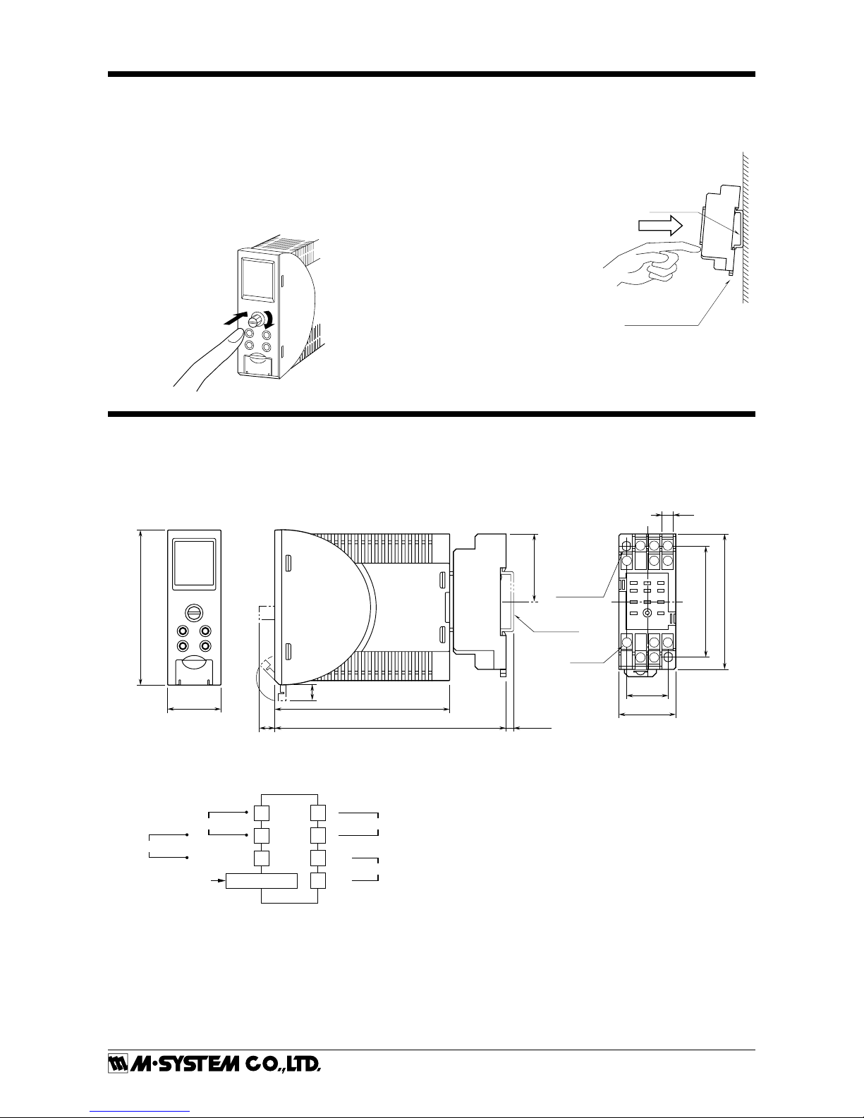
INSTALLATION
Loosen the fixing screw in front of the unit in order to separate the body from the base socket.
■ FIXING SCREW
The fixing screw can be pushed into the body when it is
not in use. Tighten the knob until the body is securely attached to the base socket. Push it into the body and turn it
clockwise to lock. Push the knob and turn it counterclockwise to unlock so that the know pops out.
■
DIN Rail
35mm wide
Spring Loaded
DIN Rail Adaptor
DIN RAIL MOUNTING
Set the base socket so that
its DIN rail adaptor is at
the bottom. Position the
upper hook at the rear side
of base socket on the DIN
rail and push in the lower.
When removing the socket,
push down the DIN rail
adaptor utilizing a minus
screwdriver and pull.
■ WALL MOUNTING
Refer to the drawings in
the shown below.
TERMINAL CONNECTIONS
Connect the unit as in the diagram below or refer to the connection diagram on the side of the unit.
■ EXTERNAL DIMENSIONS unit: mm (inch)
28.5 (1.12)
83 (3.27)
94 (3.70)
8
(.31)
124 (4.88)
22 (.87)
6 (.23)
59 (2.32)
11–M3
SCREW
72 (2.83)
36 (1.42)
29.5 (1.16)
2–4.2x5
(.17x.20)
MTG HOLE
6 (.24) deep
DIN RAIL
35mm wide
[4 (.16)]
• When mounting, no extra space is needed between units.
4
8 7
10
8
(.31)
11
56
123
9
■ CONNECTION DIAGRAM
1
4
2
+
–
OUTPUT
7
8
10
11
CONFIGURATOR
JACK
U(+)
V(–)
POWER
–
Input Current
+
+
Input Voltage
–
Page 3

M2EXV
5-2-55, Minamitsumori, Nishinari-ku, Osaka 557-0063 JAPAN
Phone: +81(6)6659-8201 Fax: +81(6)6659-8510 E-mail: info@m-system.co.jp
EM-5133-A Rev.1 P. 3 / 4
EXTERNAL VIEWS
Display
Mode Button
Set Button
Configurator Jack
Up Button
Down Button
Up
Down
Mode
Set
Output Setting DIP SW
ON
1
2
3
4
5
6
7
8
SW1
OFF
ON
1
2
3
4
5
6
7
8
SW1
OFF
PERCENT
100.00
OUTPUT
20.000
%
mA
COMPONENT FUNCTION
Display Indicates present values, setting values and abnormal information. Two types of present values at
upper and lower are displayed by setting.
Mode button Used to shift from measuring mode to each setting mode. Destination to shift is changed by the time
pressing and holding the button. Used to return from each setting mode to measuring mode. (press
and hold for 2 sec. or more)
Set button Used to change setting value of setting parameter. When at setting changeable state, used to enter
(save) the setting value. Used to move on through digits of setting value for input/output scaling at
setting changeable state,
Up button Used to shift through setting parameter, and to increase or select setting value.
Down button Used to shift through setting parameter, and to decrease or select setting value.
Configurator Jack Used to configure with M2E configurator software (model: M2ECFG). At the same time, set the lock-
out setting of the unit to ‘lock’.
DIP SWITCH
The internal DIP switch for output setting is required to
select output types before setting a precise output range using front buttons or setting with a PC.
Refer to the operating manual (EM-5133-B) for the operation with front buttons. Refer to the users manual (EM-
5147) of M2E Configurator Software (model: M2ECFG) for
setting with PC.
Output Type
SW1
1 2 3 4 5 6 7 8
0 – 20mA OFF ON OFF OFF OFF OFF ON OFF
−5 – +5V OFF OFF ON OFF ON OFF OFF ON
−10 – +10V OFF OFF ON OFF OFF ON OFF ON
CAUTION: DO NOT set DIP switches while power is
supplied. Otherwise, the unit may fail.
WIRING INSTRUCTIONS
■ SCREW TERMINAL
Torque: 0.8 N·m
■ SOLDERLESS TERMINAL
Refer to the drawing below for recommended ring tongue
terminal size. Spade tongue type is also applicable.
Applicable wire size: 0.25 to 1.65 mm2 (AWG 22 to 16)
Recommended manufacturer: Japan Solderless Terminal
MFG.Co.Ltd, Nichifu Co.,ltd
6 (.24) max
3.3 (.13) max
mm (inch)
Page 4

M2EXV
5-2-55, Minamitsumori, Nishinari-ku, Osaka 557-0063 JAPAN
Phone: +81(6)6659-8201 Fax: +81(6)6659-8510 E-mail: info@m-system.co.jp
EM-5133-A Rev.1 P. 4 / 4
CHECKING
1) Terminal wiring: Check that all cables are correctly connected according to the connection diagram.
2) Check DIP switch setting.
3) Power input voltage: Check voltage across the terminal
10 – 11 with a multimeter.
4) Input: Check that the input signal is within 0 – 100% of
the full-scale.
5) Output: Check that the load resistance meets the described specifications.
MAINTENANCE
Regular calibration procedure is explained below:
■ CALIBRATION
Without linearization, warm up the unit for at least 10
minutes. Apply 0%, 25%, 50%, 75% and 100% input signal.
Check that the output
signal for the respective input signal remains within accuracy described in the data sheet. If the output signal is out
of accuracy, when the input display value is out of accuracy,
perform the input fine adjustment. When the input display
value is correct but the output is out of accuracy, perform
the output fine adjustment. Refer to this manual, when
adjusting with front buttons. Refer to the M2ECFG users
manual (EM-5147), when adjusting with M2E Configurator
Software (model: M2ECFG). And then follow the procedure
shown below.
• INPUT FINE ADJUSTMENT
1) Set the input signal to 0 %, and adjust the input display
to 0 % by [69] Input Zero fine adjust.
2) Set the input signal to 100 %, and adjust the input display to 100 % by [70] Input Span fine adjust.
3) Again set the simulated input to 0 %, confirm the input
display.
4) If input display is shifted, repeat the procedure from 1)
to 3).
• OUTPUT FINE ADJUSTMENT
1) Set the simulated input to 0 %, and adjust the output
signal to 0 % by [71] Output Zero fine adjust.
2) Set the simulated input to 100 %, and adjust the output
signal to 100 % by [72] Output Span fine adjust.
3) Again set the simulated input to 0 %, confirm the output
signal.
4) If output signal is shifted, repeat the procedure from 1)
to 3).
LIGHTNING SURGE PROTECTION
M-System offers a series of lightning surge protector for
protection against induced lightning surges. Please contact
M-System to choose appropriate models.
 Loading...