

Page 1
MODEL: KS2TR2
http://www.m-system.co.jp/ KS2TR2 SPECIFICATIONS ES-3606 Rev.2 Page 1/5
Plug-in Signal Conditioners K-UNIT
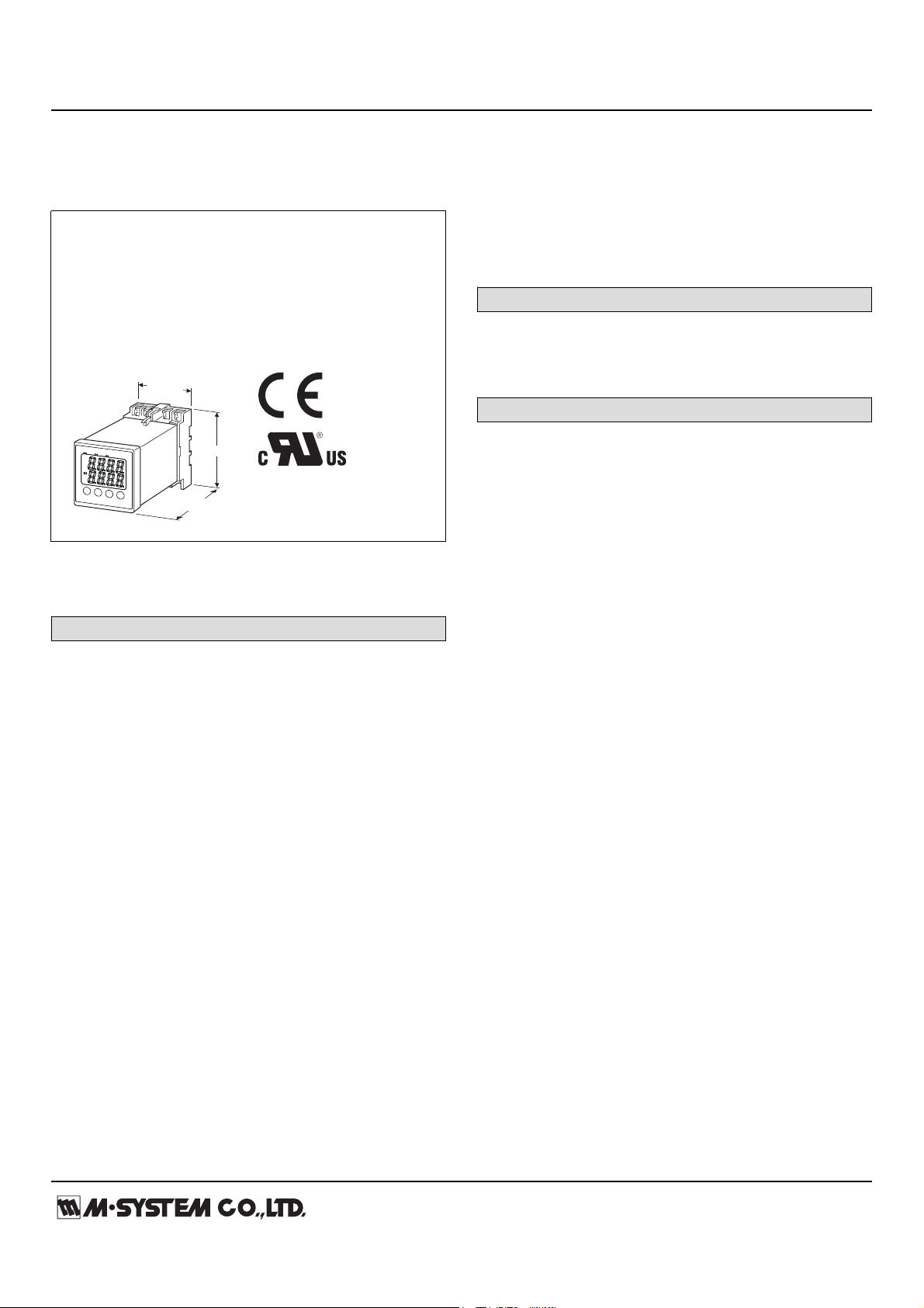
50 (1.97)
110 (4.33)
70 (2.76)
mm (inch.)
TEMPERATURE INPUT LIMIT ALARM
(digital adjustments; dual alarm trip)
Functions & Features
• Providing relay contact closures at preset DC input levels
• Dual (Hi/Lo) trip
• Front digital displays
• Programmable with front keys
Typical Applications
• Various alarm applications
MODEL: KS2TR2–1–[1][2]
ORDERING INFORMATION
• Code number: KS2TR2-1-[1][2]
Specify a code from below for each [1] and [2].
(e.g. KS2TR2-1-R/UL/Q)
• Specify the specification for option code /Q
(e.g. /SET)
TEMPERATURE INPUT
Thermocouple input
K(CA), E(CRC), J(IC), T(CC), B(RH), R, S, P(Platinel Ⅱ),
C(WRe 5-26), N
RTD input
JPt 100 (JIS ’89) , Pt 100 (JIS ’97, IEC)
[2] OPTIONS (multiple selections)
Standards & Approvals
blank: CE marking
/UL: UL approval, CE marking
Other Options
blank: none
/Q: Option other than the above (specify the specification)
SPECIFICATIONS OF OPTION: Q
EX-FACTORY SETTING
/SET: Preset according to the Ordering Information Sheet
(No. ESU-3606)
GENERAL SPECIFICATIONS
Construction: Panel flush mounting, plug-in
Connection: M3.5 screw terminals
Housing material: Flame-resistant resin (gray)
Isolation: Input to SET1 to SET2 to power
Time constant for the input filter (P-dF): 5.0 to 900.0 sec. (0
– 63 %)
Alarm relay switching delay time (P-d1, P-d2): 1 to 10 sec.;
programmable independently for each setpoint
Programming: Front key
Setpoint adjustment (ST1, ST2): -5 to +105 %;
programmable independently for each setpoint
Deadband (hysteresis) (HYS1, HYS2): 0 – 102 %;
programmable independently for each setpoint
Burnout: Upscale or downscale or no burnout
Cold junction compensation (CJM): ON or OFF; for
thermocouple input only; CJC sensor incorporated
Power ON delay (P-d0): 0 to 20 sec.
Read rate: 0.5 sec.
Temperature unit (P-F): °C, °F
Alarm mode (P-A1, P-A2): Programmable independently for
each setpoint; See Table below.
OUTPUT
1: Relay; SPDT or transfer contact
[1] POWER INPUT
AC Power
M2: 100 – 240 V AC (Operational voltage range 85 – 264 V,
47 – 66 Hz)
DC Power
R: 24 V DC
(Operational voltage range 24 V ±10 %, ripple 10 %p-p max.)
Page 2
MODEL: KS2TR2
http://www.m-system.co.jp/ KS2TR2 SPECIFICATIONS ES-3606 Rev.2 Page 2/5
Param.
Code
(P-A1)
(P-A2)
Trip
Operation
1
Set Value
Latching
Hold
Relay & LED
Behavior in
Tripped Conditions
High
Absolute
Val ue
*
*Without latching hold function, the unit is tripped upon starting
operation when the unit is set to Low alarm.
With the function, the unit is NOT tripped until the temperature
goes once above and then below the setpoint.
Alarm Modes
0
No alarm
– –
–
Without
LED ON
Coil energized
2
Low
Absolute
Val ue
Without
LED ON
Coil energized
3
High
Absolute
Val ue
With
LED ON
Coil energized
4
Low
Absolute
Val ue
With
LED ON
Coil energized
5
High
Absolute
Val ue
Without
LED ON
Coil de-energized
6
Low
Absolute
Val ue
Without
LED ON
Coil de-energized
7
High
Absolute
Val ue
With
LED ON
Coil de-energized
8
Low
Absolute
Val ue
With
LED ON
Coil de-energized
DISPLAY
Display: 4 digits of 10 mm (.39”) height, 7-segment LED
Scaling range: -1999 to 9999 counts
Measured Value (PV)/Alarm (SET1) display: Red LEDs
Alarm (SET2) parameter display: Green LEDs
PV display at abnormal input: Over range or under range
displayed
Front LEDs
Power indicator: Green LED turns on while the power is
turned on.
Measured Value (PV) indicator: Green LED turns on when PV
display is set.
Alarm SET1 indicator: Red LED turns on when the Alarm
SET1 is in tripped conditions.
Alarm SET2 Indicator: Red LED turns on when the Alarm
SET2 is in tripped conditions.
Engineering unit indication: Sticker label attached; ℃, °F,
etc.
INPUT SPECIFICATIONS
• Thermocouple
Thermocouple type and temperature range
J (IC) : (0 to 400°C or 32 to 752°F)
J (IC) : (0 to 800°C or 32 to 1472°F)
K (CA) : (0 to 400°C or 32 to 752°F)
K (CA) : (0 to 800°C or 32 to 1472°F)
K (CA) : (0 to 1200°C or 32 to 2192°F)
R : (0 to 1600°C or 32 to 2912°F)
B (RH) : (0 to 1800°C or 32 to 3272°F)
S : (0 to 1600°C or 32 to 2912°F)
T (CC) : (-199 to 200°C or -328 to 392°F)
T (CC) : (-150 to 400°C or -238 to 752°F)
E (CRC) : (0 to 800°C or 32 to 1472°F)
E (CRC) : (-199 to 800°C or -328 to 1472°F)
N : (0 to 1300°C or 32 to 2372°F)
P (Platinel Ⅱ) : (0 to 1300°C or 32 to 2372°F)
C (WRe 5-26) : (0 to 2300°C or 32 to 4172°F)
Input resistance: ≥ 1 MΩ
Burnout sensing: Approx. 0.3 μA
■ RTD
RTD type and temperature range:
Pt 100 (JIS '97, IEC): (-150 to +850°C or -238 to +1562°F)
JPt 100 (JIS '89): (-150 to +600°C or -238 to +1112°F)
Sensing current: Approx. 0.3 mA
Maximum leadwire resistance: 20 Ω per wire
OUTPUT SPECIFICATIONS
■ Relay Contact: SPDT relays
220 V AC @3 A (cos ø = 1)
30 V DC @3 A (resistive load)
Caution: N.O. and N.C. contacts could be conductive at the
same time. DO NOT connect both contacts at the same
time.
Maximum switching voltage: 220 V AC or 30 V DC
Maximum switching power: 660 VA or 90 W
Minimum load: 10 V DC @1 mA
Mechanical life: 2 × 10⁷ cycles with no loads
For maximum relay life with inductive loads, external
protection is recommended.
INSTALLATION
Power consumption
•AC:
≤ 5 VA at 100 V
≤ 6 VA at 200 V
≤ 6 VA at 264 V
•DC: ≤ 2.5 W
Operating temperature: -10 to +55°C or 14 to 131°F
(-10 to +50°C or 14 to 122°F for UL)
Operating humidity: 30 to 90 %RH (non-condensing)
Mounting: Panel flush mounting with attached
mounting bracket, surface or DIN rail
Weight: 200 g (0.44 lb)
PERFORMANCE
Display accuracy
•Thermocouple: ±0.5 % FS ± 1 digit ± 3°C (5.4°F)
Page 3

MODEL: KS2TR2
http://www.m-system.co.jp/ KS2TR2 SPECIFICATIONS ES-3606 Rev.2 Page 3/5
±1 % FS ± 1 digit ± 3°C (5.4°F) for T, E (≤ -100°C, ≤ -148
°F)
±5 % FS ± 1 digit ± 3°C (5.4°F) for B (0 – 500°C, 32 –
932°F)
±1 % FS ± 1 digit ± 3°C (5.4°F) for R (0 – 400°C, 32 –
752°F)
(In case of type B thermocouple the accuracy near 0°C may
be degraded due to the characteristic of the sensor.)
•RTD: ±0.5 % FS ± 1 digit
Setpoint accuracy: Display accuracy ± 0.1 % FS
Trip point repeatability: Included in the setpoint accuracy
Cold junction compensation error: ±3°C at 25 ±5°C (±5.4°F
at 77 ±9°F)
Burnout response: Approx. 10 sec.
Line voltage effect: Included in the display accuracy
Insulation resistance: ≥ 100 MΩ with 500 V DC
Dielectric strength: 1500 V AC @1 minute
(input to SET1 or SET2 to power)
500 V AC @1 minute (SET1 to SET2)
STANDARDS & APPROVALS
CE conformity:
EMC Directive (2004/108/EC)
EMI EN 61000-6-4: 2007/A1: 2011
EMS EN 61000-6-2: 2005
Low Voltage Directive (2006/95/EC)
EN 61010-1: 2010
Installation Category II (power)
Measurement Category II (output)
Pollution Degree 2
Input to output to power – Basic insulation (300 V)
Approval:
UL/C-UL Temperature-Indicating and -Regulating Equipment
(UL873:2013, CAN/CSA-C22.2 No.24-93:2008)
Page 4

MODEL: KS2TR2
http://www.m-system.co.jp/ KS2TR2 SPECIFICATIONS ES-3606 Rev.2 Page 4/5
EXTERNAL VIEW
A. Measured Value (PV) /
Alarm SET1 Display
B. Measured Value (PV)
Indicator LED
D. SELECT Key
C. Alarm SET2 / Parameter Display
J. Alarm SET2 Indicator LED
H. Alarm SET1 Indicator LED
G. Power Indicator LED
F. DOWN Key
E. UP Key
B
Measured Value (PV) Indicator LED
A
Measured Value (PV) / Alarm SET1 Display
C
Alarm SET2 / Parameter Display
D
SELECT Key
E
UP Key
F
DOWN Key
G
Power Indicator LED
H
Alarm SET1 Indicator LED
J
Alarm SET2 Indicator LED
Ref.
Component Name
Light turns on when the Alarm SET2 is in tripped conditions.
Displaying either of Measured Value (PV) or Alarm Setpoint Value (SET1)
Light turns on when the Measured Value (PV) is displayed.
Displaying either of Alarm Setpoint Value (SET2) or parameter type code.
Used for confirming current setpoints and switching between parameter blocks.
Pressing the key increases display values.
They change continuously when it is kept pressed.
Pressing the key decreases display values.
They change continuously when it is kept pressed.
Light turns on while the power is turned on.
Light turns on when the Alarm SET1 is in tripped conditions.
Function
Page 5

MODEL: KS2TR2
http://www.m-system.co.jp/ KS2TR2 SPECIFICATIONS ES-3606 Rev.2 Page 5/5
EXTERNAL DIMENSIONS & TERMINAL ASSIGNMENTS unit: mm (inch)
5678
211110
39
4
[3.5] (.14)
110 (4.33)
7.5
(.3)
48 (1.89)
48 (1.89)
t
1 ≤ t ≤ 8
(.04 ≤ t ≤.31)
MOUNTING
BRACKET
71.5 (2.81)
70 (2.76)
40 (1.57)
50 (1.97)
7.8 (.31)
CLAMP
(top & bottom)
DIN RAIL
35mm wide
2–4.5 (.18) dia.
MTG HOLE
25 (.98) deep
1 1–M3.5
SCREW
PACKING
7
(.28)
PANEL
1.5 (.06)
35.4 (1.39)
45
45
+0.5
0
+0.5
0
85 MIN.
63 MIN.
7
8
10
11
9
2
3
1
4
5
6
N.C.
N.O.
COM
SET1
N.C.
N.O.
COM
SET2
U(+)
V(–)
POWER
B
B
A
RTD
THERMOCOUPLE
+
–
comp.
leadwire
+
–
T/C
Display/
Setting
Digital
Computation
A/D
Converter
RY
RY
Base Socket
CJC
Sensor
Specifications are subject to change without notice.
PANEL CUTOUT unit: mm
■PANEL CUTOUT
SCHEMATIC CIRCUITRY & CONNECTION DIAGRAM
 Loading...