

Page 1
INSTRUCTION MANUAL
FREQUENCY SCALER
(eld-programmable; built-in excitation)
BEFORE USE ....
Thank you for choosing M-System. Before use, please check
contents of the package you received as outlined below.
If you have any problems or questions with the product,
please contact M-System’s Sales Office or representatives.
■ PACKAGE INCLUDES:
Signal conditioner (body + base socket) .............................(1)
■ MODEL NO.
Confirm Model No. marking on the product to be exactly
what you ordered.
■ INSTRUCTION MANUAL
This manual describes necessary points of caution when
you use this product, including installation, connection,
hardware setting and basic maintenance procedures.
When you need to change software settings, please refer to
the Operation Manual for Model PU-2x (EM-9255), Section
B.
This unit is factory adjusted and calibrated according to the
Ordering Information included in the product package. If
you don’t need to change the pre-adjusted setting, you can
skip the sections on hardware setting and calibration in this
manual and the Operation Manual for Model PU-2x.
MODEL
■ AND ....
•The unit is designed to function as soon as power is supplied, however, a warm up for 10 minutes is required for
satisfying complete performance described in the data
sheet.
JFR2
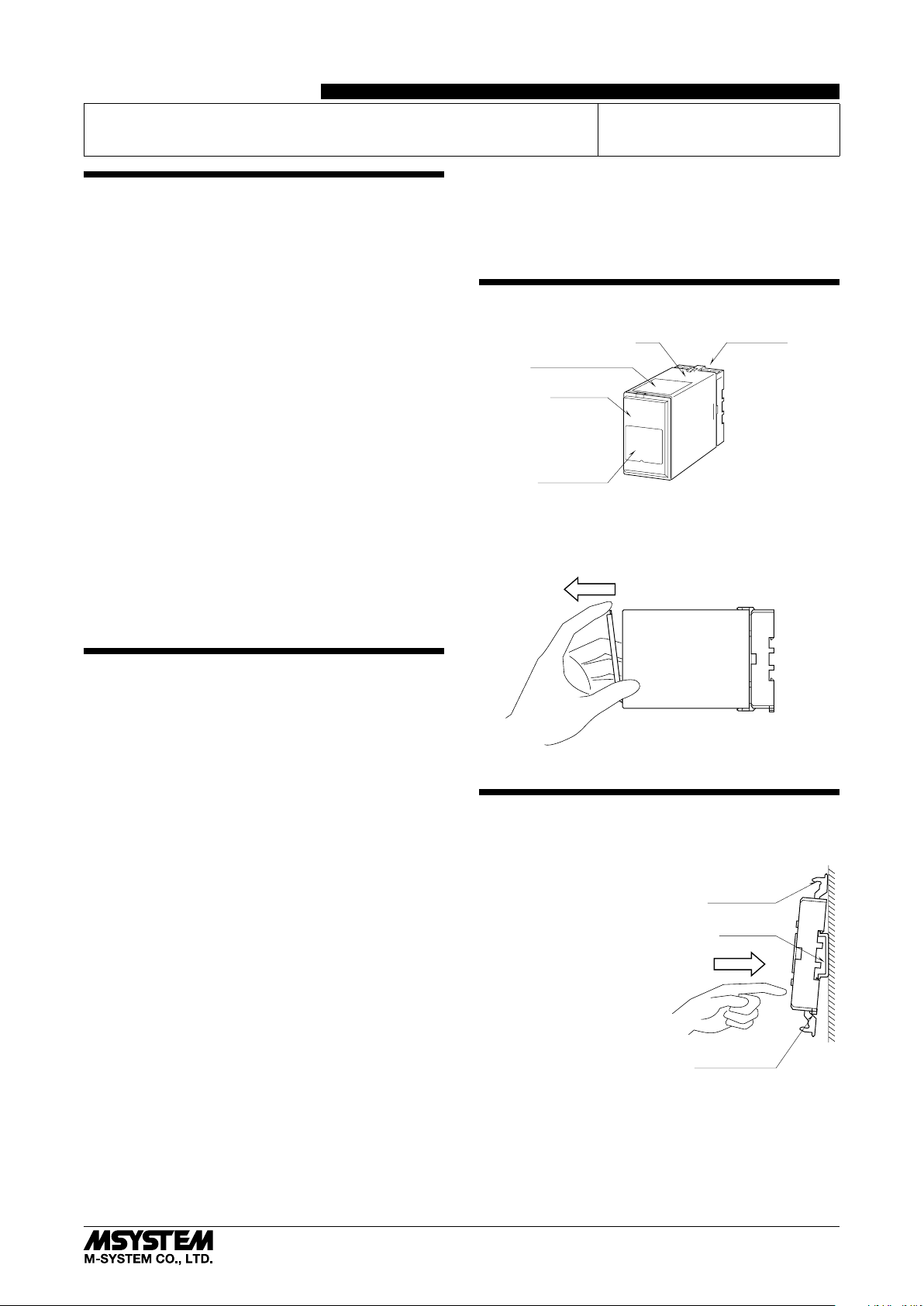
COMPONENT IDENTIFICATION
Body Base Socket
Connection Diagram
Front Cover
Specifications
■ HOW TO OPEN THE FRONT COVER
Position your finger on the hook at the top of front cover
and pull.
POINTS OF CAUTION
■ POWER INPUT RATING & OPERATIONAL RANGE
•Locate the power input rating marked on the product and
confirm its operational range as indicated below:
85 – 132V AC rating: 85 – 132V, 47 – 66 Hz, approx. 6VA
12V, 24V and 48V DC rating: Rating ±10%, approx. 3.3W
110V DC rating: 85 – 150V, approx. 3.3W
■ GENERAL PRECAUTIONS
•Before you remove the unit from its base socket or mount
it, turn off the power supply and input signal for safety.
■ ENVIRONMENT
•Indoor use.
•When heavy dust or metal particles are present in the
air, install the unit inside proper housing with sufficient
ventilation.
•Do not install the unit where it is subjected to continuous
vibration. Do not subject the unit to physical impact.
•Environmental temperature must be within -5 to +60°C
(23 to 140°F) with relative humidity within 30 to 90% RH
in order to ensure adequate life span and operation.
■ WIRING
•Do not install cables close to noise sources (relay drive
cable, high frequency line, etc.).
•Do not bind these cables together with those in which
noises are present. Do not install them in the same duct.
The shape of base socket may be different
for some models.
INSTALLATION
Detach the yellow clamps located at the top and bottom of
the unit to separate the body from the base socket.
■ DIN RAIL MOUNTING
Set the base socket so that its
DIN rail adaptor is at the bottom. Position the upper hook
at the rear side of base socket
on the DIN rail and push in
the lower. When removing
the socket, push down the
DIN rail adaptor utilizing a
minus screwdriver and pull.
■ WALL MOUNTING
Refer to “EXTERNAL DIMENSIONS.”
DIN Rail Adaptor
Shape and size of the base socket
are slightly different with various
socket types.
Clamp
(top & bottom)
DIN Rail
35mm wide
Spring Loaded
5-2-55, Minamitsumori, Nishinari-ku, Osaka 557-0063 JAPAN
Phone: +81(6)6659-8201 Fax: +81(6)6659-8510 E-mail: info@m-system.co.jp
EM-1581 Rev.4 P. 1 / 8
Page 2
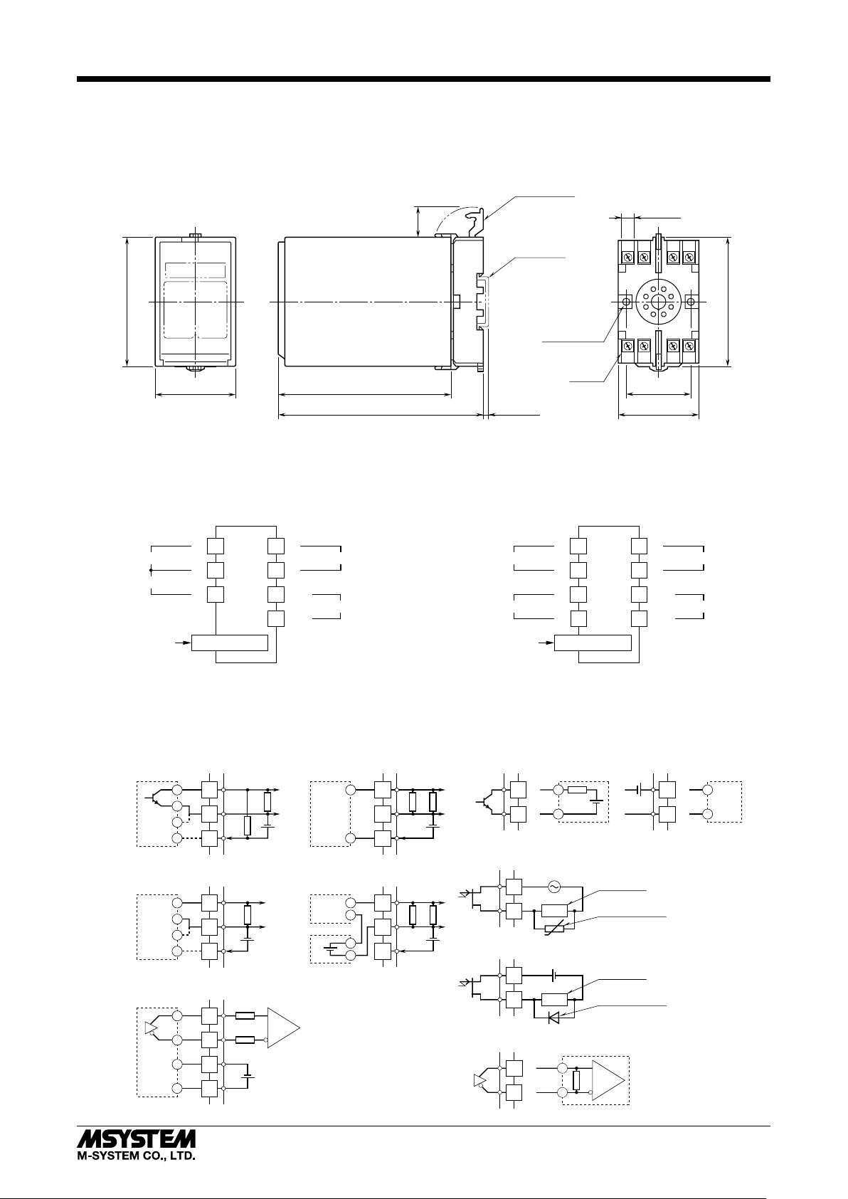
TERMINAL CONNECTIONS
Connect the unit as in the diagram below or refer to the connection diagram on the top of the unit.
■ EXTERNAL DIMENSIONS unit: mm (inch)
CLAMP
(top & bottom)
20
(.79)
DIN RAIL
35mm wide
JFR2
7.8 (.31)
3456
80 (3.15)
50 (1.97) 107 (4.21)
127 (5) [3.3 (.13)]
■ CONNECTION DIAGRAM
■ OPEN COLLECTOR, MECHANICAL CONTACT,
VOLTAGE PULSE or 2-WIRE CURRENT PULSE INPUT
+
INPUT
SENSOR EXCITATION
PU-2x
With 24V excitation and open collector/mechanical contact input,
the voltage across the terminals 3 – 4, divided in the waveform shaper,
is of approx. 16V.
3
–
4
+
5
MODULAR JACK
+
1
2
7
8
OUTPUT
–
U(+)
POWER
V(–)
2–4.5 (.18) dia.
MTG HOLE
15 (.59) deep
8–M3.5
2187
SCREW
40 (1.57)
50 (1.97)
• When mounting, no extra space is needed between units.
■ RS-422 LINE DRIVER INPUT
INPUT
SENSOR EXCITATION
PU-2x
+
3
–
6
+
5
–
4
MODULAR JACK
+
1
2
7
8
OUTPUT
–
U(+)
POWER
V(–)
80 (3.15)
Input Connection Examples
■ Open Collector or
Mechanical Contact
+
3
–
4
–
PWR
+
5
5kΩ
■ Voltage Pulse
+
3
–
4
–
PWR
+
5
■ RS-422 Line Driver Pulse
+
3
–
6
–
PWR
4
+
5
Vsns
Vsns
Output Connection Examples
■ 2-Wire Current Pulse
• Built-in Excitation
2-WIRE
PICK-UP
Vsns
• External DC Supply
2-WIRE
PICK-UP
DC SUPPLY
–
100Ω
3
4
+
5
–
100Ω
3
+
4
+
5
–
■ Open Collector
+
1
–
Vsns
2
■ Noncontact AC/DC Switch
• AC Powered
1
2
Vsns
• DC Powered
+
–
LOAD
U
1
LOAD
2
+
–
5-2-55, Minamitsumori, Nishinari-ku, Osaka 557-0063 JAPAN
Phone: +81(6)6659-8201 Fax: +81(6)6659-8510 E-mail: info@m-system.co.jp
■ RS-422 Line Driver Pulse
+
1
–
2
+
–
■ Voltage Pulse
Relay or
Counter Coil
Varistor or Spark
Quenching Circuit
Relay or
Counter Coil
Spark Quenching
Diode
+
–
+
+
1
–
–
2
EM-1581 Rev.4 P. 2 / 8
Page 3

EXPLANATIONS OF TERMS & FUNCTIONS
■ LOW-END CUTOUT
The output frequency is forcibly set to 0 Hz when the input
frequency is below the low-end cutout setting by the PU-2x
Programming Unit. It is selectable from 0.3 to 100% of the
selected input frequency range (e.g. 30 Hz – 10 kHz for the
input frequency range 0 – 10 kHz). Use the same unit as
that for the input.
The low-end cutout is reset when the input frequency exceeds the cutout value by 1%. For example, with the input
frequency range 0 – 100 kHz, the input span frequency 10
kHz and the low-end cutout set to 1 kHz; the output equals
0 Hz while the input is within 0 – 1 kHz. When it goes
higher than 1.1 kHz, the output becomes proportional to the
input.
When the input frequency range setting is changed, the
low-end cutout value is automatically reset to the default
value, 0.3% of the range.
■ SCALING FACTOR, INPUT SPAN FREQUENCY & OUT-
PUT SPAN FREQUENCY
The scaling factor, rate of output frequency divided by input
frequency, are determined by two parameters: input span
frequency and output span frequency.
Although there are also input zero frequency and output
zero frequency, they are fixed to zero (0) Hz.
The output frequency is limited up to 115% of the output
span frequency.
JFR2
■ DETECTING PULSE EDGE
• Open Collector & Mechanical Contact:
OFF (input monitor LED ON) to ON (input monitor LED
OFF)
• Voltage Pulse
A pulse rise detected when the input voltage goes above
the detecting level (input monitor LED ON); a pulse sink
detected when it goes below the level (input monitor LED
OFF).
• Two-wire Current Pulse
The input resistor (100 Ω) converts the current signal (0 –
25 mA) into 0 – 2.5 V. A pulse rise detected when the voltage goes above the detecting level (input monitor LED ON);
a pulse sink detected when it goes below the level (input
monitor LED OFF).
■ INPUT/OUTPUT WAVEFORMS
The figure below shows an example of the output waveform
when the input is changed from 100% to 0% (0 Hz), with no
conversion to one-shot.
The output, as shown in the figure, does not drop to 0 Hz immediately after the input does, but rather decreases gradually down to 0 Hz.
The time required for the output reaches 0 Hz is longer
when the input frequency range is lower.
In general, it becomes shorter when the low-end cutout
value is greater.
INPUT
Input 100% Input 0%
OUTPUT
Output 100%
Output frequency decreasing
Time
5-2-55, Minamitsumori, Nishinari-ku, Osaka 557-0063 JAPAN
Phone: +81(6)6659-8201 Fax: +81(6)6659-8510 E-mail: info@m-system.co.jp
EM-1581 Rev.4 P. 3 / 8
Page 4

HARDWARE SETTING & CALIBRATION
Modular Jack
Input Monitor LED
3
2
4
1
Detecting Level Adj.
Detecting Level Adj. Pin
Pulse Amplitude Selector
5
0
SW3
6
9
7
8
1
2
3
4
5
SW1
6
7
8
1
2
3
4
SW2
5
6
7
8
Sensor Excitation Adj.
■ PULSE AMPLITUDE (rotary switch) (*) Factory setting
For RS-422 line driver pulse, this setting is invalid.
For voltage pulse input, select the pulse amplitude (Vp-p)
among the switch positions 0 through 6. For open collector,
mechanical contact or two-wire current pulse input, set the
switch to 7. DO NOT SET to 8 or 9. The power supply to the
unit must be turned off when changing the setting.
SW PULSE AMPLITUDE MAX. INPUT VOLTAGE
0
1
2
3
4
5
6*
7 (*)
1
50 – 100 Vp-p
25 – 50 Vp-p
10 – 25 Vp-p
5 – 10 Vp-p
1 – 5 Vp-p
0.5 – 1 Vp-p
0.1 – 0.5 Vp-p
Open collector, Mechanical contact or
Two-wire current pulse
*1. Maximum frequency limited 50 kHz.
Unused
Unused
Input Type Selectors
ON
1
2
3
4
5
6
7
8
50V
50V
25V
10V
5V
1V
0.5V
JFR2
■ DIP SWITCH SETTING (*) Factory setting
For RS-422 line driver pulse, the noise filter setting is invalid.
SW2 is not used. Turn all switches to OFF.
The power supply to the unit must be turned off when
changing the setting.
• Input Type
ON
OFF
OFF
SW1
OFF
ON
OFF
INPUT TYPE
Open collector (*)
Mechanical contact
1 2 3 4 5 6
ON OFF ON OFF OFF ON
Voltage pulse OFF OFF ON OFF OFF ON
Two-wire current pulse OFF ON ON OFF OFF ON
RS-422 line driver pulse OFF OFF OFF ON ON OFF
• Noise Filter
Choose an appropriate noise filter setting according to input
frequency. (The unit may not function within the described
accuracy level if no filter is used.)
‘High’ setting is used for input ranges ≤ 1 Hz.
‘Low’ setting is used for input ranges ≤ 1 kHz.
NOISE FILTER SW1-7 SW1-8
High
Low (*)
None
■ CAUTION FOR RS-422 LINE DRIVER PULSE
For RS-422 line driver pulse, the input amplitude, detecting level and noise filter settings are all invalid. However,
in order to prevent errors in setting, set these switches as
follows:
Input amplitude = 50 – 100 Vp-p (SW=0)
Detecting level = 0V
Noise filter = None
■ EXAMPLE 1: VOLTAGE PULSE with Amplitude 5 Vp-p, DC Offset 2.5 V, Input Frequency 1 kHz
Input type: Voltage pulse
Input frequency: 1 kHz (range and span frequency selected with the PU-2x)
Input amplitude: 1 – 5 Vp-p
Detecting level:
2.5 V (DC Offset × Sensitivity Scale = 2.5 × 1/1 = 2.5 V)
(Set to the offset value after it is scaled by the sensitivity
scale.)
Noise filter: Low
The rotary switch and DIP switch are configured as shown to
SW3 SW1 SW2
5
6
4
7
3
8
2
1
0
ON
9
12345678
the right.
■ EXAMPLE 2: VOLTAGE PULSE with Amplitude 30 Vp-p, DC Offset 15 V, Input Frequency 50 Hz
Input type: Voltage pulse
Input frequency: 100 Hz (range and span frequency selected with the PU-2x)
Input amplitude: 25 – 50 Vp-p
Detecting level:
1.5 V (DC Offset × Sensitivity Scale = 15 × 1/10 = 1.5 V)
(Set to the offset value after it is scaled by the sensitivity
scale.)
Noise filter: High
The rotary switch and DIP switch are configured as shown to
SW3
4
3
2
1
5
6
7
8
9
0
SW1 SW2
ON
12345678
the right.
ON
12345678
Not Used (All OFF)
ON
1 2345678
Not Used (All OFF)
5-2-55, Minamitsumori, Nishinari-ku, Osaka 557-0063 JAPAN
Phone: +81(6)6659-8201 Fax: +81(6)6659-8510 E-mail: info@m-system.co.jp
EM-1581 Rev.4 P. 4 / 8
Page 5

■ DETECTING LEVEL
Determine the appropriate detecting level referring to the flow chart below.
START
JFR2
Voltage pulse input or
Two-wire current pulse input?
Yes
Confirm the Sensitivity Scale in Table 1
below.
Assign the value in the following equation.
1
Detecting Level (V)*
DC Offset (V)*
Adjust the detecting level to the value
calculated above following the procedure
explained below.
*1. Rounded off to one decimal place.
*2. For 2-wire current pulse, divide a current input (mA)
by 10 and convert it into voltage (V).
=
2
× Sensitivity Scale
No
Table 1
SW PULSE AMPLITUDE SENSITIVITY SCALE
0
1
2
3
4
5
6
7
50 – 100 Vp-p
25 – 50 Vp-p
10 – 25 Vp-p
5 – 10 Vp-p
1 – 5 Vp-p
0.5 – 1 Vp-p
0.1 – 0.5 Vp-p
Open collector
Mechanical contact
1/20
1/10
1/5
1/2
1
5
10
1
Two-wire current pulse
A specific sensitivity scale is applied according to the pulse
amplitude setting. The scaled input voltage is then compared to the detecting voltage level (0 – 5 V).
The scaled H level voltage must be equal to or higher than
the detecting level so that the pulse state is accurately detected. (Refer to the instruction manual for detailed information about adjusting the detecting level.)
Open collector input or
Mechanical contact input?
Yes
Adjust the detecting level
appropriate for the sensor
excitation voltage.
Excitation
≥ 10V DC
7 – 10V DC
5 – 7V DC
Detect. Level
2V
1.5V
1V
No
Adjust the detecting level
to 0V appropriate for
RS-422 line driver pulse
input.
• Setting Examples
Voltage pulse (DC Offset = Pulse Amplitude / 2)
PULSE
AMPLITUDE (Vp-p)
50
50
30
25
15
10
7.5
5
3.5
2
1
0.5
AMPLITUDE
RANGE (Vp-p)
50 – 100
25 – 50
25 – 50
10 – 25
10 – 25
5 – 10
5 – 10
1 – 5
1 – 5
1 – 5
0.5 – 1
0.1 – 0.5
DETECTING
LEVEL (V)
1.3
2.5
1.5
2.5
1.5
2.5
1.9
2.5
1.8
1
2.5
2.5
Two-wire current pulse (DC Offset = Pulse Amplitude / 2)
PULSE
AMPLITUDE (mAp-p)
15 (1.5 Vp-p)
25 (2.5 Vp-p)
AMPLITUDE
RANGE
Set to open collector,
mechanical contact or
two-wire current pulse
DETECTING
LEVEL (V)
0.8
1.3
Set DC offset to 0 V for 100 Vp-p pulse input.
5-2-55, Minamitsumori, Nishinari-ku, Osaka 557-0063 JAPAN
Phone: +81(6)6659-8201 Fax: +81(6)6659-8510 E-mail: info@m-system.co.jp
EM-1581 Rev.4 P. 5 / 8
Page 6

• How to Change the Detecting Level
Input Monitor LED
Voltmeter
Detecting Level Adj.
Detecting Level Adj. Pin
3
2
4
1
5
0
SW3
6
9
7
8
1
2
3
4
5
SW1
6
7
8
1
2
3
4
SW2
5
6
7
8
V
–
Connect to Terminal 4
of the base socket.
A voltmeter of class 0.5 or better accuracy with pointed
probes is required.
1) Connect the negative probe of voltmeter to the terminal 4
of base socket.
2) If you need a noise filter, set the SW1-7 and SW1-8 in
advance.
3) Connect the positive probe to the test pin and turn the
Detecting Level Adjustment until the meter shows desired value.
4) Apply input signals and check that input monitor LED
(PL1) blinks according to the input signal.
If the LED does not blink, the detecting level may be out
of pulse amplitude range. Check the pulse amplitude
and the DC offset again and readjust the detecting level.
JFR2
■ SENSOR EXCITATION ADJUSTMENT
You can change the sensor excitation voltage with the sensor excitation adj. located behind the front cover. If you
need to change it, check that the required current is within
the specification.
• How to Change the Excitation
A voltmeter and ammeter of class 0.5 or better accuracy are
required.
SENSOR EXC.
Ammeter
A
V
PU-2x
Voltmeter
–
4
+
5
MODULAR JACK
+
1
OUTPUT
–
2
7
U(+)
POWER
8
V(–)
1) Connect the voltmeter across the terminal 5 – 4.
2) Connect the ammeter to terminal 5.
3) Turn the potentiometer until the meter shows the desired value.
Check that the current value indicated on the ammeter
is within the allowable limit. If the value is greater than
the limit, lower the voltage value or connect a separate
power source. Otherwise, the transmitter may fail.
24
12
VOLTAGE (V)
5
25
Voltage (V) × Current (A) ≤ 600mW
60 120
CURRENT (mA)
5-2-55, Minamitsumori, Nishinari-ku, Osaka 557-0063 JAPAN
Phone: +81(6)6659-8201 Fax: +81(6)6659-8510 E-mail: info@m-system.co.jp
EM-1581 Rev.4 P. 6 / 8
Page 7

JFR2
SOFTWARE SETTING
Please refer to the Operation Manual for Model PU-2x (EM-9255), Section B: (B-1) INTRODUCTION, (B-2) GENERAL OPERATION DESCRIPTION, (B-3) OPERATION FLOW CHART for general information.
[GROUP 01]
ITEM MDFY. INPUT DATA DISPLAY DEFAULT CONTENTS
01 S N/A MAINTENANCE SWITCH
0 MTSW: MON.MODE 0: Data indication only.
1 MTSW: PRG.MODE 1: All ‘P’ marked parameters are modifiable.
02 P Alphanumeric TG: XXXXXXXXXX N/A Tag name entry (10 characters max.)
03 P Numeric (%) OUTPER XXX.XX N/A Output in % and simulated output
05 D No input INPPER XXX.XX N/A Input in %
06 D No input INPFRQ XXX.XX N/A Input frequency (unit as in ITEM 11)
07 D No input N/A
SW: IN_V 1/20 SW = 0, Voltage pulse, Sensitivity scale = 1/20
SW: IN_V 1/10 SW = 1, Voltage pulse, Sensitivity scale = 1/10
SW: IN_V 1/5 SW = 2, Voltage pulse, Sensitivity scale = 1/5
SW: IN_V 1/2 SW = 3, Voltage pulse, Sensitivity scale = 1/2
SW: IN_V 1/1 SW = 4, Voltage pulse, Sensitivity scale = 1/1
SW: IN_V 5/1 SW = 5, Voltage pulse, Sensitivity scale = 5/1
SW: IN_V 10/1 SW = 6, Voltage pulse, Sensitivity scale = 10/1
SW: IN_OC, mA SW = 7, Open collector, mechanical contact or two-wire
SW: no use SW = 8, (not used)
SW: no use SW = 9, (not used)
SW: IN_RS-422 DIP switch set to RS-422 line driver pulse
11 P 5
0 INRNG: 10 mHz 0 – 10 mHz
1 INRNG: 100 mHz 0 – 100 mHz
2 INRNG: 1.0 Hz 0 – 1.0 Hz
3 INRNG: 10 Hz 0 – 10 Hz
4 INRNG: 100 Hz 0 – 100 Hz
5 INRNG: 1.0 kHz 0 – 1.0 kHz
6 INRNG: 10 kHz 0 – 10 kHz
7 INRNG: 100 kHz 0 – 100 kHz
12 P Numeric INSPN XXXXXX 1.0000 Input span frequency (unit as in ITEM 11)
13 P 6
0 OUTRNG: 1 mHz (5)* 0 – 1 mHz
1 OUTRNG: 10 mHz 0 – 10 mHz
2 OUTRNG: 100 Hz 0 – 100 mHz
OUTRNG: 1.0 Hz 0 – 1.0 Hz
OUTRNG: 10 Hz 0 – 10 Hz
OUTRNG: 100 Hz 0 – 100 Hz
OUTRNG: 1.0 kHz 0 – 1.0 kHz
7 OUTRNG: 10 kHz 0 – 10 kHz
14 P Numeric OUTSPN XXXXXX 1.0000 Output span frequency (unit as in ITEM 13)
(20.00)*
15 P Numeric DRPOUT XXXXXX 0.3 Low-end cutout frequency (unit as in ITEM 11)
18 P Numeric SMPL RATE XXX 1 Averaging non-uniform pulses
Input specification selected with the front rotary switch
current pulse
Input frequency range
Output frequency range
*( ) Output code R: Noncontact AC/DC switch
*( ) Output code R: Noncontact AC/DC switch
Deadband fixed at 1% (Low-end cutout is reset when
the input exceeds the setting by 1%.)
Input pulses are divided and then multiplied by the
ratio so that the output waveform is uniform (stable).
Range ≤ 0 – 100 Hz : Ratio 1 – 255
0 – 1 kHz : 1 – 25
0 – 10 Hz : 1 – 2
0 – 100 Hz : Not selectable (fixed at 1)
5-2-55, Minamitsumori, Nishinari-ku, Osaka 557-0063 JAPAN
Phone: +81(6)6659-8201 Fax: +81(6)6659-8510 E-mail: info@m-system.co.jp
EM-1581 Rev.4 P. 7 / 8
Page 8

ITEM MDFY. INPUT DATA DISPLAY DEFAULT CONTENTS
19 P Numeric (%) FINZER XXX.XX 0.00 Fine zero adjustment
OUTPER XXX.XX Indicates the output in % when data is input.
20 P Numeric (%) FINSPN XXX.XX 100.00 Fine span adjustment
OUTPER XXX.XX Indicates the output in % when data is input.
Modication Code
D : No modification (writing) possible. Used only for monitoring (reading).
S : Modifiable at any time.
P : Modifiable only when the MAINTENANCE SWITCH is in the ‘PRG’ mode.
ROM Version Indication
[GROUP 00] [ITEM 99]
CHECKING
1) Terminal wiring: Check that all cables are correctly connected according to the connection diagram.
2) Power input voltage: Check voltage across the terminal
7 – 8 with a multimeter.
3) Check input signal.
4) Sensor excitation: Check that the load for the sensor excitation is within the permissible limit.
5) Output: Check that the load resistance meets the described specifications.
JFR2
LIGHTNING SURGE PROTECTION
M-System offers a series of lightning surge protectors for
protection against induced lightning surges. Please contact
M-System to choose appropriate models.
5-2-55, Minamitsumori, Nishinari-ku, Osaka 557-0063 JAPAN
Phone: +81(6)6659-8201 Fax: +81(6)6659-8510 E-mail: info@m-system.co.jp
EM-1581 Rev.4 P. 8 / 8
 Loading...