

Page 1
JC-CU
5-2-55, Minamitsumori, Nishinari-ku, Osaka 557-0063 JAPAN
Phone: +81(6)6659-8201 Fax: +81(6)6659-8510 E-mail: info@m-system.co.jp
EM-9042 Rev.1 P. 1 / 6
HUB MODULE
(
CUnet
)
MODEL
JC-CU
INSTRUCTION MANUAL
BEFORE USE ....
Thank you for choosing M-System. Before use, please check
contents of the package you received as outlined below.
If you have any problems or questions with the product,
please contact M-System’s Sales Office or representatives.
■ PACKAGE INCLUDES:
Hub module .........................................................................(1)
DIN rail mounter slider ......................................................(1)
■ MODEL NO.
Confirm that the model number described on the product is
exactly what you ordered.
■ INSTRUCTION MANUAL
This manual describes necessary points of caution when
you use this product, including installation, connection and
basic maintenance procedures.
POINTS OF CAUTION
■ CONFORMITY WITH EU DIRECTIVES
•The equipment must be mounted inside a panel.
•Use dual-shield cables (Shinko Seisen Industry Model
ZHY262PBA) for the network. If it is not sufficient, use
a ferrite core (TDK Model ZCAT3035-1330 or equivalent)
for the network cable.
•Expose the shield at a part of the cable cover, clip it with a
Loop clamp (Seiwa Electric Mfg. Model E08P03 or equivalent), and ground it to the internal panel of the control
panel.
•The actual installation environments such as panel configurations, connected devices and connected wires may
affect the protection level of this module when it is integrated in a panel system. The user may have to review
the CE requirements in regard to the whole system and
employ additional protective measures to ensure CE conformity.
■ POWER INPUT RATING & OPERATIONAL RANGE
Locate the power input rating marked on the product and
confirm its operational range as indicated below:
24V DC rating: 24V ±10%
16−32V DC rating: 15−33V DC
Power consumtpion:
JC-CU-3: approx. 0.9 W, JC-CU-7: approx. 1.2 W
■ GENERAL PRECAUTIONS
Before you remove the module or mount it, turn off the
power
supply and input signal for safety.
■ ENVIRONMENT
•Indoor use
•When heavy dust or metal particles are present in the air,
install the module inside proper housing with sufficient
ventilation.
•Do not install the module where it is subjected to continuous vibration. Do not subject the module to physical
impact.
•Environmental temperature must be within -10 to +55°C
(14 to 131°F) with relative humidity within 10 to 90% RH
in order to ensure adequate life span and operation.
■ WIRING
•Do not install cables close to noise sources (relay drive
cable, high frequency line, etc.).
•Do not bind these cables together with those in which
noises are present. Do not install them in the same duct.
■ AND ....
The module is designed to function as soon as power is supplied, however, a warm up for 10 minutes is required for satisfying complete performance described in the data sheet.
Page 2
JC-CU
5-2-55, Minamitsumori, Nishinari-ku, Osaka 557-0063 JAPAN
Phone: +81(6)6659-8201 Fax: +81(6)6659-8510 E-mail: info@m-system.co.jp
EM-9042 Rev.1 P. 2 / 6
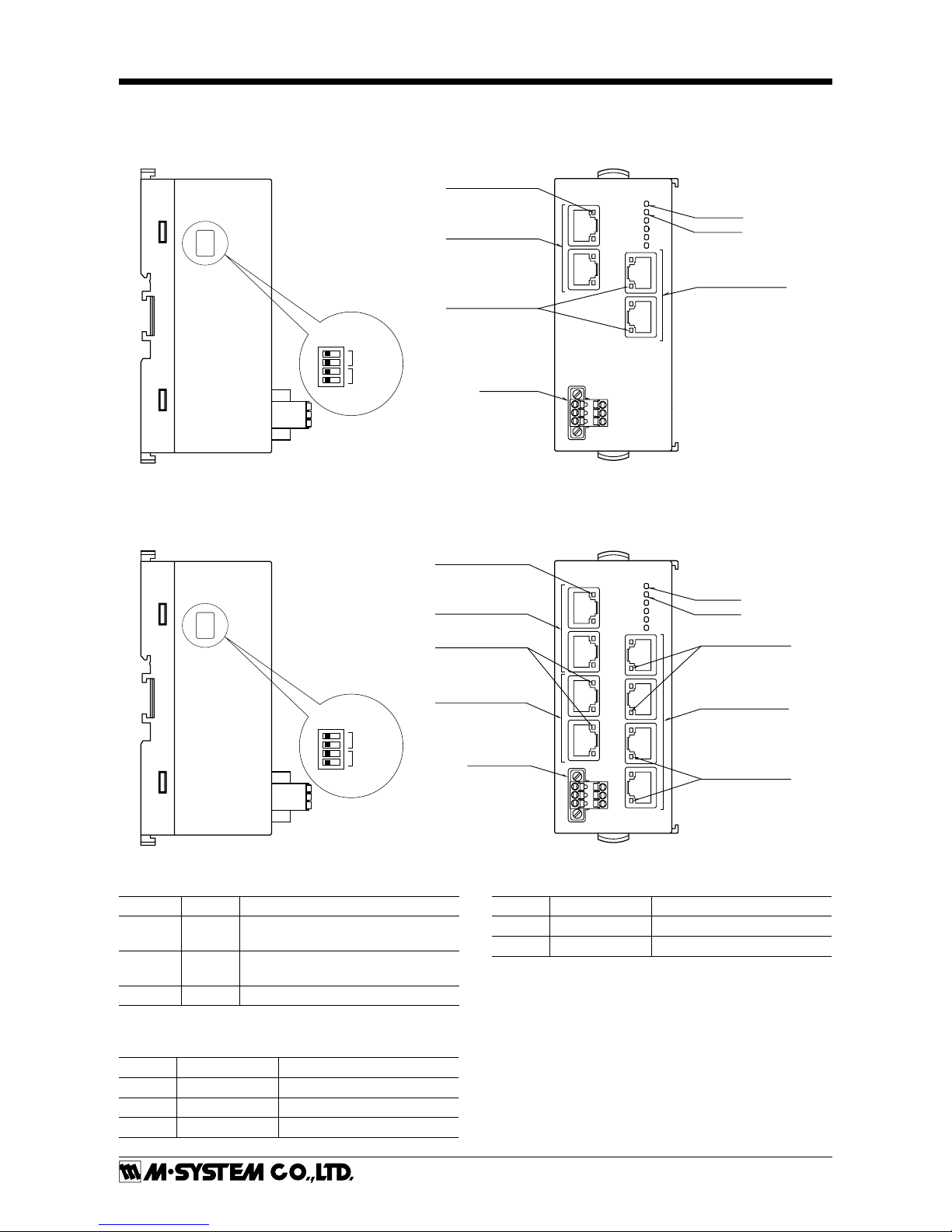
COMPONENT IDENTIFICATION
■ I/O TYPE : 3 3port
• SIDE VIEW
SW1
ON ➞
SW1
1
2
3
4
Operating Mode Setting
DIP SW(SW1
)
Terminating
Resistor
Transfer Rate
ON ➞
• FRONT VIEW
PWR+
PWR
-
FE
LNK1
LNK2
CU1
CU2
CU0A
CU0B
LNK0
PWR
ERR
ERR LED
RJ-45 Modular Jack
for Trunk
Status Indicator LED
RJ-45 Modular Jack
for Feeder
Status Indicator LED
Power Supply
Connector
PWR LED
■ I/O TYPE : 7 7port
PWR+
PWR
-
FE
LNK4
LNK1
LNK2
LNK3
CU1
CU2
CU3
CU4
CU0A
CU0B
CU5
CU6
LNK0
LNK5
LNK6
Status Indicator LED
RJ-45 Modular Jack
for Trunk
Status Indicator LED
RJ-45 Modular Jack
for Feeder
Power Supply
Connector
RJ-45 Modular Jack
for Feeder
Status Indicator LED
Status Indicator LED
PWR
ERR
ERR LED
PWR LED
• SIDE VIEW
SW1
ON ➞
SW1
1
2
3
4
Operating Mode Setting
DIP SW(SW1
)
Terminating
Resistor
Transfer Rate
ON ➞
• FRONT VIEW
■ STATUS INDICATOR LED
ID COLOR FUNCTION
PWR Green
ON when internal power supply is supplied normally
ERR Red
ON when receiving error packet at
least one communication port
LNK 0−6 Green ON at normal communication
■ OPERATING MODE
• Transfer rate (SW1-1, 1-2)
SW1-1 SW1-2 TRANSFER RATE
OFF OFF 12Mbps (*)
ON OFF 6Mbps
OFF ON 3Mbps
■ TERMINATING RESISTOR (SW1-3, 1-4)
SW1-1 SW1-2 TERMINATING RESISTOR
OFF OFF Disable (*)
ON ON Enable
(*) Factory setting
Page 3

JC-CU
5-2-55, Minamitsumori, Nishinari-ku, Osaka 557-0063 JAPAN
Phone: +81(6)6659-8201 Fax: +81(6)6659-8510 E-mail: info@m-system.co.jp
EM-9042 Rev.1 P. 3 / 6
WIRING INSTRUCTIONS
1. PWR + Power Supply
2. PWR − Power Supply
3. FE Functional earth
1
2
3
Cable connector: TFMC1,5 / 5–STF–3,5
(Phoenix Contact) (included in the package)
Applicable wire size:
0.2 − 1.5 mm2; stripped length 10 mm
Recommended solderless terminal
• AI0,25−10YE 0.25 mm2 (Phoenix Contact)
• AI0,34−10TQ 0.34 mm
2
(Phoenix Contact)
• AI0,5−10WH 0.5 mm
2
(Phoenix Contact)
• AI0,75−10GY 0.75 mm
2
(Phoenix Contact)
• A1−10 1.0 mm
2
(Phoenix Contact)
• A1,5−10 1.5 mm
2
(Phoenix Contact)
■ POWER SUPPLY
■ NETWORK
Reccommended cable connector: TM21P–88P (Hirose Electric)
(not included in the package)
1
2
3
4
5
6
7
8
1. NC
2. NC
3. TR+
4. TR–
5. NC
6. NC
7. NC
8. SLD
Unused
Unused
Network (+)
Network (–)
Unused
Unused
Unused
Shield
Feeder (CU1, CU2, CU3, CU4, CU5, CU6)
1. NC
2. NC
3. TR+
4. TR–
5. NC
6. NC
7. NC
8. SLD
Unused
Unused
Network (+)
Network (–)
Unused
Unused
Unused
Shield
Trunk (CU0A, CU0B)
• COMMUNICATION CONNECTOR PIN ASSIGNMENT CODE: 1
1
2
3
4
5
6
7
8
1. NC
2. NC
3. NC
4. TR–
5. TR+
6. NC
7. NC
8. SLD
Unused
Unused
Unused
Network (–)
Network (+)
Unused
Unused
Shield
Feeder (CU1, CU2, CU3, CU4, CU5, CU6)
1. NC
2. NC
3. NC
4. TR–
5. TR+
6. NC
7. NC
8. SLD
Unused
Unused
Unused
Network (–)
Network (+)
Unused
Unused
Shield
Trunk (CU0A, CU0B)
• COMMUNICATION CONNECTOR PIN ASSIGNMENT CODE: 2
■ CONNECTION WITH OTHERS
CUnet I/O Module
CUnet I/O Module
CUnet I/O Module
HUB Module
Trunk CU0A/CU0B
Feeder CU1 – CU6
TR+
TR−
SLD
TR+
TR−
SLD
TR+
TR−
SHIELD
TR+
TR−
SLD
TR+
TR−
SLD
Terminating
Resistor
Terminating
Resistor
Terminating
Resistor
Terminating
Resistor
Note: Be sure to turn ON the switch of the terminating resistor located at both ends of the modules.
Page 4

JC-CU
5-2-55, Minamitsumori, Nishinari-ku, Osaka 557-0063 JAPAN
Phone: +81(6)6659-8201 Fax: +81(6)6659-8510 E-mail: info@m-system.co.jp
EM-9042 Rev.1 P. 4 / 6
MOUNTING INSTRUCTIONS
■ DIN RAIL MOUNTING
• Mounting
1) Set the upper hook at the rear side of the module on the
DIN rail.
2) Push in the lower.
1
2
• Dismounting
1) Push down the DIN rail mounter slider with tip of a
minus screwdriver.
2) Pull the lower of the module.
3) Remove the upper hook of the module from the DIN rail.
1
2
3
■ SURFACE MOUNTING
1) Insert the DIN rail mounter slider until it clicks once, as
shown below.
1
2) Mount the module with M4 screws referring the External Dimensions. (Torque: 1.4 N·m)
EXTERNAL DIMENSIONS module: mm (inch)
50(1.97) [3 (.12)]
115 (4.52)[4 (.18)] [4 (.18)][7 (.28)] [7 (.28)]
[4(.16)]
73(2.87)
55(2.17)
DIN RAIL
(35 mm wide)
2–4.3 (.17) dia Mtg Hole
4 (.16) deep
Page 5

JC-CU
5-2-55, Minamitsumori, Nishinari-ku, Osaka 557-0063 JAPAN
Phone: +81(6)6659-8201 Fax: +81(6)6659-8510 E-mail: info@m-system.co.jp
EM-9042 Rev.1 P. 5 / 6
CONNECTION DIAGRAM
Connect the unit as in the diagram below.
In order to improve EMC performance, bond the FE terminal to ground.
Caution: FE terminal is NOT a protective conductor terminal.
■ JC−CU−3−11
SLD
NC
NC
NC
TR+
TR−
NC
NC
CU0A
COMMUNICATION
1
2
4
3
6
5
8
7
SLD
NC
NC
NC
TR+
TR−
NC
NC
SLD
NC
NC
NC
TR+
TR−
NC
NC
SLD
NC
NC
NC
TR+
TR−
NC
NC
CU0B
COMMUNICATION
CU1
CU2
1
2
4
3
6
5
8
7
1
2
3
1
2
3
1
2
4
3
5
6
8
7
FE
PWR
−
PWR +
POWER (IN)
FE
PWR
−
PWR +
POWER (OUT)
1
2
4
3
5
6
8
7
+
−
■ JC−CU−7−11
1
2
3
1
2
3
FE
PWR
−
PWR +
POWER (IN)
FE
PWR
−
PWR +
POWER (OUT)
+
−
SLD
NC
NC
NC
TR+
TR−
NC
NC
CU0A
COMMUNICATION
1
2
4
3
6
5
8
7
SLD
NC
NC
NC
TR+
TR−
NC
NC
CU0B
COMMUNICATION
1
2
4
3
6
5
8
7
SLD
NC
NC
NC
TR+
TR−
NC
NC
SLD
NC
NC
NC
TR+
TR−
NC
NC
CU1
CU6
1
2
4
3
5
6
8
7
1
2
4
3
5
6
8
7
■ JC−CU−3−12
SLD
NC
NC
NC
NC
TR−
TR+
NC
SLD
NC
NC
NC
NC
TR−
TR+
NC
CU0A
COMMUNICATION
1
2
4
3
6
5
8
7
CU0B
COMMUNICATION
1
2
4
3
6
5
8
7
CU1
CU2
1
2
3
1
2
3
1
2
4
3
5
6
8
7
FE
PWR
−
PWR +
FE
PWR
−
PWR +
1
2
4
3
5
6
8
7
+
SLD
NC
NC
NC
NC
TR−
TR+
NC
SLD
NC
NC
NC
NC
TR−
TR+
NC
■ JC−CU−7−12
CU1
CU6
1
2
3
1
2
3
FE
PWR
−
PWR+
POWER (IN)
FE
PWR
−
PWR+
POWER (OUT)
+
−
CU0A
COMMUNICATION
1
2
4
3
6
5
8
7
CU0B
COMMUNICATION
1
2
4
3
6
5
8
7
SLD
NC
NC
NC
NC
TR−
TR+
NC
SLD
NC
NC
NC
NC
TR−
TR+
NC
SLD
NC
NC
NC
NC
TR−
TR+
NC
SLD
NC
NC
NC
NC
TR−
TR+
NC
1
2
4
3
5
6
8
7
1
2
4
3
5
6
8
7
Page 6

JC-CU
5-2-55, Minamitsumori, Nishinari-ku, Osaka 557-0063 JAPAN
Phone: +81(6)6659-8201 Fax: +81(6)6659-8510 E-mail: info@m-system.co.jp
EM-9042 Rev.1 P. 6 / 6
SYSTEM CONFIGURATION EXAMPLES
Rt : Terminating Resistor
Rt
Rt
Rt
Rt
Rt
Rt
Rt
HUB Module
(Model: JC−CU)
HUB Module
(Model: JC−CU)
CUnet
I/O Module
CUnet
I/O Module
CUnet
I/O Module
Note 1) Max. transmission distance between CUnet I/O module and HUB module, HUB module and HUB module is as follows.
100 m at 12 Mbps, 200 m at 6 Mbps and 300 m at 3 Mbps.
Note 2) Be sure to connect CU0A/CU0B to the host side.
Note 3) The terminating resistor must be enabled for the modules at both end of the communication line. The terminating resistor is
incorporated in the feeder side port of the HUB module.
MOUNTING REQUIREMENTS module: mm (inch)
125 (4.92)
CONFIGURATIONS
•The configurations such as communication mode and
transfer rate must be same for all modules connected to
the communication line.
•The terminating resistor must be enabled for the modules at both end of the communication line. The terminating resistors of the modules other than them must be
disabled. (The terminating resistor is incorporated in the
feeder side port of the JC-CU as it is end of the communication line.)
•In order to use the hub module, it is required to set frame
option at any CUnet I/O module connected to network.
For detailed information about settings refer to the manual of your CUnet I/O module.
 Loading...