

Page 1

5-2-55, Minamitsumori, Nishinari-ku, Osaka 557-0063 JAPAN
Phone: +81(6)6659-8201 Fax: +81(6)6659-8510 E-mail: info@m-system.co.jp
EM-8621 Rev.5 P. 1 / 15
INSTRUCTION MANUAL
ETHERNET/RS-485 ADAPTOR
(Modbus use)
MODEL
GR8-EM
BEFORE USE ....
Thank you for choosing M-System. Before use, please check
contents of the package you received as outlined below.
If you have any problems or questions with the product,
please contact M-System’s Sales Office or representatives.
■ PACKAGE INCLUDES:
Ethernet/RS-485 adaptor ....................................................(1)
■ MODEL NO.
Confirm Model No. marking on the product to be exactly
what you ordered.
■ INSTRUCTION MANUAL
This manual describes necessary points of caution when
you use this product, including installation, connection and
basic maintenance procedures.
POINTS OF CAUTION
■ CONFORMITY WITH EU DIRECTIVES
• The equipment must be mounted inside a panel.
• The actual installation environments such as panel configurations, connected devices, connected wires, may affect the protection level of this unit when it is integrated
in a panel system. The user may have to review the CE
requirements in regard to the whole system and employ
additional protective measures to ensure the CE conformity.
■ POWER INPUT RATING & OPERATIONAL RANGE
• Locate the power input rating marked on the product and
confirm its operational range as indicated below:
24V DC rating: 24V ±10%, ≤ 1.5W
■ GENERAL PRECAUTIONS
• Before you remove the unit or mount it, turn off the power
supply for safety.
■ ENVIRONMENT
• Indoor use.
• When heavy dust or metal particles are present in the
air, install the unit inside proper housing with sufficient
ventilation.
• Do not install the unit where it is subjected to continuous
vibration. Do not subject the unit to physical impact.
• Environmental temperature must be within -10 to +55°C
(14 to 131°F) with relative humidity within 10 to90% RH
in order to ensure adequate life span and operation.
■ WIRING
• Do not install cables close to noise sources (relay drive
cable, high frequency line, etc.).
• Do not bind these cables together with those in which
noises are present. Do not install them in the same duct.
■ AND ....
• The unit is designed to function as soon as power is supplied, however, a warm up for 10 minutes is required for
satisfying complete performance described in the data
sheet.
Page 2
GR8-EM
5-2-55, Minamitsumori, Nishinari-ku, Osaka 557-0063 JAPAN
Phone: +81(6)6659-8201 Fax: +81(6)6659-8510 E-mail: info@m-system.co.jp
EM-8621 Rev.5 P. 2 / 15
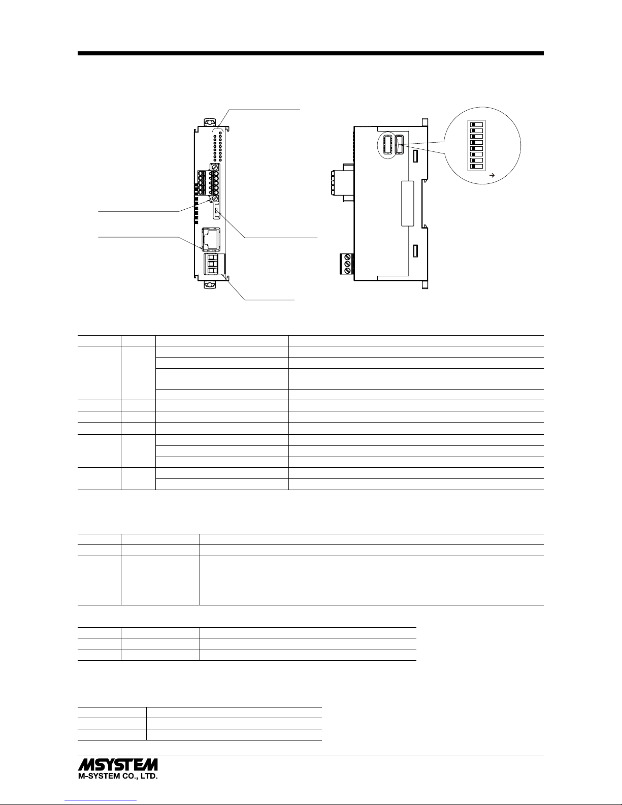
COMPONENT IDENTIFICATION
Connector for
Power Supply
Terminating Resistor
Setting SW
Status Indicator LED
Function Setting DIP SW
1
SW1
2
3
4
5
6
7
8
ON
RJ-45 Connector for
Ethernet
Connector for
RS-485 Communication
■ FRONT VIEW ■ RIGHT SIDE VIEW
■ STATUS INDICATOR LED
ID Color Light Module Status
RUN Green
Blinking (1-sec cycle) Normal mode
Blinking in low speed (2-sec cycle) Maintenance mode (with SW1-2 ON)
Blinking in high speed
(0.4-sec cycle)
Error (device error when the unit wouldn’t recover even after power
reactivation)
OFF Power is off or device error
ERR Red ON Data error from RS-485 device
RD Green ON Receiving data from the paired RS-485 station
SD Green ON Sending data to the paired RS-485 station
LINK Green
ON Being linked with 10BASE or 100BASE
Blinking Sending/receiving data
OFF No link detected
LK100 Green
ON Being linked with 100BASE
OFF Being linked with 10BASE or Not linked
■ DIP SW SETTING
(*) Factory default setting
• IP Address
SW1-1 Mode Function
OFF (*) Normal mode Set with configurator
ON
Factory default
mode
When starting up with the SW ON, the unit temporarily operates by the factory default settings
of network configuration, user ID and password.
The stored settings, however, are maintained and the unit returns to the original settings upon
restarting at normal mode. When network settings are changed during factory default mode,
the changed settings are stored.
• Maintenance mode
SW1-2 Mode Function
OFF (*) Normal mode Normal operation
ON Maintenance mode Stop output (Modbus function 05, 06, 15, 16 are disabled)
Note: Be sure to set unused SW1-3 through 1-8 to OFF.
■ TERMINATING RESISTOR SETTING SW
• Terminating resistor
TERM INCORPORATED TERMINATING RESISTOR
OFF Disabled
ON (*) Enabled
Page 3
GR8-EM
5-2-55, Minamitsumori, Nishinari-ku, Osaka 557-0063 JAPAN
Phone: +81(6)6659-8201 Fax: +81(6)6659-8510 E-mail: info@m-system.co.jp
EM-8621 Rev.5 P. 3 / 15
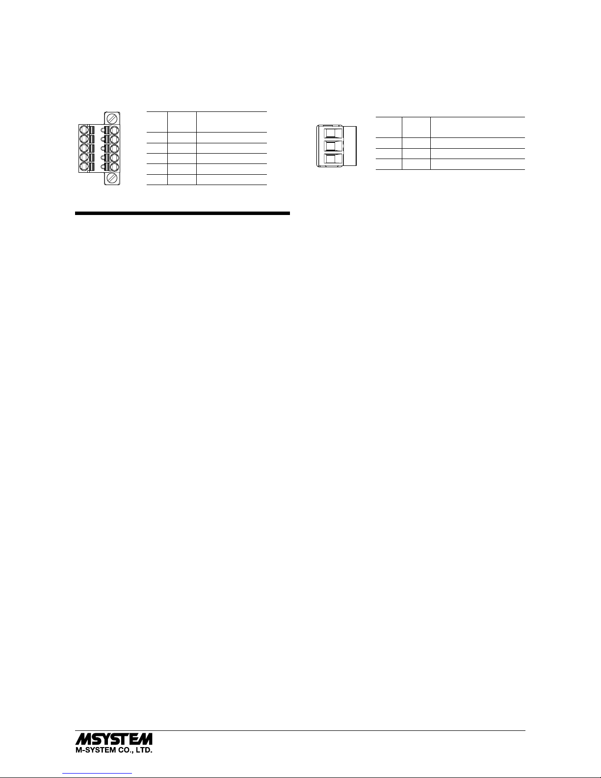
■ RS-485 CONNECTOR TERMINAL ASSIGNMENT
Unit side connector: MC1,5/5-GF-3,5
(Phoenex Contact)
Cable side connector: TFMC1,5/5-STF-3,5
(Phoenex Contact)
No. ID FUNCTION
5 FE FE
4 SH SHIELD
3 DG DG
2 DB DB
1 DA DA
5
4
3
2
1
1
2
3
■ POWER SUPPLY TERMINAL ASSIGNMENT
Unit side connector: MSTB2,5/3-G
(Phoenex Contact)
Cable side connector: MSTB2,5/3-ST
(Phoenex Contact)
No. ID FUNCTION
1 (+) Power supply 24V (+)
2 (–) Power supply 24V (–)
3 FE1 Power supply earth
WIRING INSTRUCTIONS
■ EURO TYPE CONNECTOR TERMINAL (POWER SUPPLY)
Applicable connector: MSTB2,5/3-ST (Phoenix Contact)
attached to the product
Applicable wire size: 0.2 – 2.5 mm
2
Stripped length: 7 mm
Recommended pin terminals :
AI0,25-6BU 0.25 mm
2
(Phoenix Contact)
AI0,34-6TQ 0.34 mm
2
(Phoenix Contact)
AI0,5-6WH 0.5 mm
2
(Phoenix Contact)
AI0,75-6GY 0.75 mm
2
(Phoenix Contact)
AI1-6RD 1.0 mm
2
(Phoenix Contact)
AI1,5-6BK 1.5 mm
2
(Phoenix Contact)
AI2,5-6BU 2.5 mm
2
(Phoenix Contact)
■ TENSION CLAMP TERMINAL BLOCK (RS-485)
Applicable connector: TFMC1,5/5-STF-3,5 (Phoenix Contact)
attached to the product
Applicable wire size: 0.2 – 1.5 mm
2
Stripped length: 10 mm
Recommended pin terminals:
AI0,25-10YE 0.25 mm
2
(Phoenix Contact)
AI0,34-10TQ 0.34 mm
2
(Phoenix Contact)
AI0,5-10WH 0.5 mm
2
(Phoenix Contact)
AI0,75-10GY 0.75 mm
2
(Phoenix Contact)
Page 4

GR8-EM
5-2-55, Minamitsumori, Nishinari-ku, Osaka 557-0063 JAPAN
Phone: +81(6)6659-8201 Fax: +81(6)6659-8510 E-mail: info@m-system.co.jp
EM-8621 Rev.5 P. 4 / 15
INSTALLATION
■ COUPLED WITH DL8
The unit coupled with DL8 is used by connecting to DL8 and R8 series I/O modules. First, mount all the DL8 and I/O modules
with the power OFF. Connect the unit in the same manner to DL8 and I/O modules. Attach the protective cover of DL8 to
GR8-EM.
Note: Make sure to install the unit at the end of all the other modules. With the unit installed between DL8 and I/O modules, I/O
modules after the unit can not perform internal communication or the power can not be supplied to these I/O modules.
Confirm that the locking clamps of the unit are set. Insert the unit straight in perpendicularly to the rail such that the
grooves of the unit and the module on the immediate left engage each other. (A & B in the below figure)
A
B
• HOW TO INSTALL
Conrm that the locking clamps of the unit are set. Insert the unit straight in perpendicularly to the rail such that the grooves of the
unit and the module on the immediate left engage each other. (A & B in the below gure)
• HOW TO ATTACH PROTECTIVE COVER
Align the hooks on the cover with the grooves of the unit and slide the cover straight until the hooks are latched.
groove
hook
When removing the cover by DIP SW setting, pull it out while squeezing the hooks inward.
Page 5
GR8-EM
5-2-55, Minamitsumori, Nishinari-ku, Osaka 557-0063 JAPAN
Phone: +81(6)6659-8201 Fax: +81(6)6659-8510 E-mail: info@m-system.co.jp
EM-8621 Rev.5 P. 5 / 15
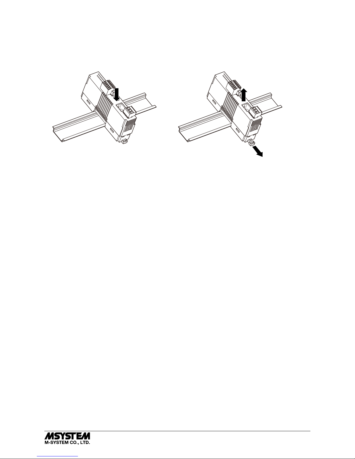
■ SINGLE USE
• HOW TO INSTALL
A) Hang the upper hook at the rear side of unit on the DIN rail. Push in the lower in keeping pressing the unit to the DIN rail.
B) To remove the unit, push down the DIN rail adaptor using a minus screwdriver. Pull out the lower part of the unit.
Remove the upper part from the DIN rail.
Note: When the unit is mounted on a DIN rail attached on the wall surface in vertical direction, use of an attachment
plate to prevent the module from sliding down is recommended.
Page 6

GR8-EM
5-2-55, Minamitsumori, Nishinari-ku, Osaka 557-0063 JAPAN
Phone: +81(6)6659-8201 Fax: +81(6)6659-8510 E-mail: info@m-system.co.jp
EM-8621 Rev.5 P. 6 / 15
TERMINAL CONNECTION
Connect the unit as in the diagram below.
■ EXTERNAL DIMENSIONS unit: mm (inch)
[4 (.16)] [5 (.20)]
73 (2.87)
55 (2.17)
73 (2.87)
55 (2.17)
115 (4.53)
6
(.24)
7
(.28)
115 (4.53)
6
(.24)
7
(.28)
6
(.24)
7
(.28)
3 (.12)
• COUPLED WITH DL8 • SINGLE USE
1
24 (.94)
3 (.12)
24 (.94)
■ CONNECTION DIAGRAM
RJ-45 CONNECTOR
To other
RS-485 devices
DA
DB
DG
+
–
FE1
SH
FE
POWER
MODBUS WIRING CONNECTION
DA
DB
DG
SH
FE
GR8-EM
DA
DB
DG
SLD
FG
RS-485 devices
Terminating
Resistor
*
*Tu rn the terminating resistor SW “ON” to use the incorporated terminating resistor.
Page 7

GR8-EM
5-2-55, Minamitsumori, Nishinari-ku, Osaka 557-0063 JAPAN
Phone: +81(6)6659-8201 Fax: +81(6)6659-8510 E-mail: info@m-system.co.jp
EM-8621 Rev.5 P. 7 / 15
COMMUNICATION
■ Ethernet, Modbus / TCP
• Standard: IEEE 802.3u
• Protocol: TCP/IP (compatible to Modbus/TCP Standard by Schneider Automation)
• Transmission speed: 10 / 100M bps (Auto Negotiation)
• Transmission media: 10BASE-T (STP cable; Category 5)
• 100BASE-TX (STP cable; Category 5e)
• Maximum segment length: 100 meters
• Number of connections: 8
• Configuration: Via a web browser software
IP address: 192.168.0.1 (Factory default setting)
Port No.: 502 (Factory default setting)
Subnet mask
Default gateway
User name, password
Modbus exception response
Connection time out: 1 min. (*) to 60 min.*
1
*1. Connection is severed automatically when no query is sent from the host for a certain time.
■ RS-485, Modbus / RTU
• Protocol: Modbus RTU
• Configuration: Bus type multi-drop
• Standard: Conforms to TIA/EIA-485-A
• Communication: Half-duplex, asynchronous, no procedure
• Transmission distance: 500 meters max.
• Transmission media: Shielded twisted-pair cable (CPEV-S 0.9 dia.)
• Terminating resistor: Built-in 110 Ω (DIP Switch, default: enabled)
• Configuration: Via a web browser software
• Baud rate: 2.4, 4.8, 9.6, 19.2 (*), 38.4 , 57.6, 115.2 kbps
Stop bit: 1 (*), 2
Parity: None, Even, Odd (*)
Read timeout: 1000 msec. (*), 10 – 10 000 msec.
Write timeout: 1000 msec. (*), 10 – 10 000 msec.
Cache function: Enabled (*), disabled
Inter-frame interval: 10 msec. (*), 0 – 500 msec.
(*) Factory default setting
■ SUPPORTED Modbus COMMANDS
Read Coil Status (01)
Read Input Status (02)
Read Holding Registers (03)
Read Input Registers (04)
Force Single Coils (05)
Preset Single Registers (06)
Diagnostics (08)
Fetch Comm. Event Counter (11)
Fetch Comm. Event Log (12)
Force Multiple Coils (15)
Preset Multiple Registers (16)
Report Slave ID (17)
Page 8

GR8-EM
5-2-55, Minamitsumori, Nishinari-ku, Osaka 557-0063 JAPAN
Phone: +81(6)6659-8201 Fax: +81(6)6659-8510 E-mail: info@m-system.co.jp
EM-8621 Rev.5 P. 8 / 15
■ CACHE FUNCTION
• General
The GR8-EM regularly communicates with the client (RS-485) I/O modules regardless of the presence or absence of requests
from the host (Ethernet) and stores data in its Cache area. Whenever a query is received from the host, the GR8-EM sends
data stored in the Cache without loss of time to scan the client each time.
• When many devices are connected to RS-485
When devices connected to RS-485 and requests of query increase in number, update cycle for data stored in a cache becomes
slow and data become delayed data against actual data. If this delay causes problem, disable the cache.
• Modbus commands supported for Cache function
Read Coil Status (01)
Read Input Status (02)
Read Holding Registers (03)
Read Input Registers (04)
• Number of Cache
Up to 100 Cache areas (100 queries of the commands supported for Cache) are usable.
Each Cache is managed with Slave address, Function code, Begin address and Number of register.
One Cache area is shared by identical queries. If one or more of the above differs, another Cache area is assigned.
When the number of Cache areas reaches 100, following queries will be handled as normal queries without Cache function.
Note: If no query is sent from the host for 10 seconds, the Cache is disabled.
If data received from the client result in three consecutive errors, or there is no communication between the client for 10 sec.,
the Cache is disabled.
• Modbus/TCP & Modbus RTU
Query and Response message formats are different between Modbus/TCP (Ethernet) and Modbus RTU (RS-485). For detailed
explanations, please refer to Modbus Protocol Reference Guide (EM-5650).
For example, when a query is sent to read data addresses 30017 to 30018 at the slave address 1 and ‘12345678’ is stored at
these addresses: (hexadecimal)
QUERY
Modbus/TCP 00 01 00 00 00 06 01 04 00 10 00 02
(1) (2) (3) (4) (5) (6)
Modbus RTU 01 04 00 10 00 02 70 0E
(4) (5) (6) (7)
RESPONSE
Modbus/TCP 00 01 00 00 00 07 01 04 04 12 34 56 78
(1) (2) (3) (4) (5) (6)
Modbus RTU 01 04 04 12 34 56 78 80 B0
(4) (5) (6) (7)
(1) Transaction identifier (2 bytes): The value in the query is copied into the response.
(2) Protocol identifier (2 bytes): Fixed to zero (0).
(3) Length (2 bytes): Number of following bytes.
(4) Unit identifier (1 byte): Modbus RTU slave address.
(5) Function Code (1 byte)
(6) Data fields (variable length): Related to the Function Code.
(7) CRC check (2 bytes)
(4), (5) and (6) are common to both Modbus/TCP and Modbus RTU.
Modbus/TCP is preceded by six (6) bytes of data, while Modbus RTU is followed by a CRC.
Page 9

GR8-EM
5-2-55, Minamitsumori, Nishinari-ku, Osaka 557-0063 JAPAN
Phone: +81(6)6659-8201 Fax: +81(6)6659-8510 E-mail: info@m-system.co.jp
EM-8621 Rev.5 P. 9 / 15
SYSTEM CONFIGURATION EXAMPLE
Devices other than the GR8-EM in below provided by the user.
RS-485
Remote I/O modules
Hub
DL8 Client
24V DC
power
DL8
GR8-EM
I/O modules
Note: It is not available to supply the power via DL8.
Supply the power with the connector for power supply.
■ COUPLED WITH DL8
Communication Adaptor
(model: GR8-EM)
Communication Adaptor
(model: GR8-EM)
RS-485
Remote I/O (R7M etc.)
Max 31 nodes
RS-485
STP Cable
PC Recorder
(model: MSR128, MSR2K)
Hub
STP Cable
(10BASE-T, 100BASE-TX)
R3, R5, R6, R7 Series
Interface Modules
(model: R3-NM1, R5-NM1,
R6-NM1, R6-NM2)
■ SINGLE USE
Page 10
GR8-EM
5-2-55, Minamitsumori, Nishinari-ku, Osaka 557-0063 JAPAN
Phone: +81(6)6659-8201 Fax: +81(6)6659-8510 E-mail: info@m-system.co.jp
EM-8621 Rev.5 P. 10 / 15
STARTUP WITH DEFAULT SETTINGS
When starting up with DIP SW1-1 on the right side of the unit “ON”, the unit temporarily operates by the factory default settings of network configuration and user login password to setting menu as in the table below. (Factory default mode)
Use the factory default mode to confirm the settings when you forget IP address or login password. The original set values are
displayed by opening the setting menu. The settings can be changed at the factory default mode as well.
Restart the unit with SW1-1 “OFF” to return to the normal mode.
ITEM FACTORY DEFAULT SETTING
IP Address 192.168.0.1
Subnet Mask 255.255.255.0
Default Gateway 0.0.0.0
User Name admin
Password admin
CONFIGURATION WITH WEB BROWSER
The GR8-EM is capable of Web server. A PC, tablet or smart phone can configure the GR8-EM via Ethernet.
Note: As the GR8-EM employs only Ethernet I/F, A PC, tablet or smart phone, which has only wireless LAN I/F, cannot be connected
directly. Provide a wireless LAN access point etc. by users.
Though the web server is designed for applicable to many web browsers supporting HTML5, operation with all web browsers
or environment cannot be guaranteed. Please notice that even with the web browsers checked operation by M-System, there
are possibilities that display is corrupted or specific function does not work by configuration of the web browsers or installed
security software.
COMPATIBLE WEB BROWSERS CHECKED BY M-SYSTEM
DEVICES WEB BROWSERS
PCs with Windows 7, Windows 8.1, Windows 10 Internet Explorer 11.0.47
Firefox 62.0.3
Chrome 69.0.3497.100
Edge 44.17763.1.0
iPhone or iPad with iOS 11.4.1
Tablet or smart phone with Android 8.0.0
Safari 11.4.1
Chrome 69.0.3497.100
■ CONFIGURATION
When IP address is factory default, 192.168.0.1, set the address for PCs 192.168.0.5 etc. which can communicate with
192.168.0.1, and connect the unit and the PC with Ethernet cable. After connection, specify and connect to http://192.168.0.1/
with the web browser of the PC, tablet or smart phone.
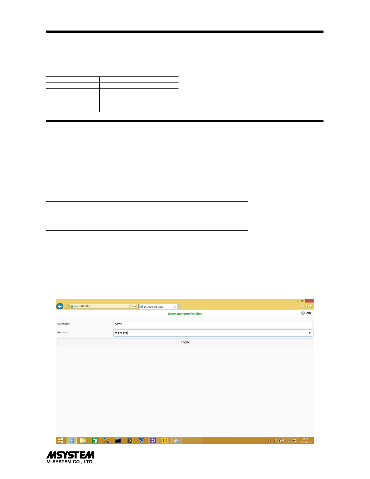
The following initial screen is displayed on the web browser, after the unit is started up and the devices are connected via
the web browser. The view of the web browser differs depending on your OS, web browser and its version. The views on this
instruction manual are with Internet Explorer on Windows 8.1. The IP address is 192.168.0.1.
Page 11

GR8-EM
5-2-55, Minamitsumori, Nishinari-ku, Osaka 557-0063 JAPAN
Phone: +81(6)6659-8201 Fax: +81(6)6659-8510 E-mail: info@m-system.co.jp
EM-8621 Rev.5 P. 11 / 15
■ SETTING MENU
Enter user name and password on the “User authentication” of the initial view and login. The default user name and password is “admin” for both.
After login, the following Setting Menu is displayed. Choosing each menu enables to move on to each information or setting
view.
Pressing “LANG” button enables to select the language between English and Japanese.
■ PASSWORD
Set the user name and password to be required for user authentication to connect the pages for various settings. After setting, clicking “Save” button on the upper right corner enables to save them in the unit. Clicking “Back” button enables to
return previous view before saving.
ITEM DESCRIPTION
Username Set the user name for login to setting menu. Max. 64 characters are available. *
1
Password Set the password for login to setting menu. Max. 64 characters are available. *
1
*1. ”, # and \ are excluded.
Page 12
GR8-EM
5-2-55, Minamitsumori, Nishinari-ku, Osaka 557-0063 JAPAN
Phone: +81(6)6659-8201 Fax: +81(6)6659-8510 E-mail: info@m-system.co.jp
EM-8621 Rev.5 P. 12 / 15
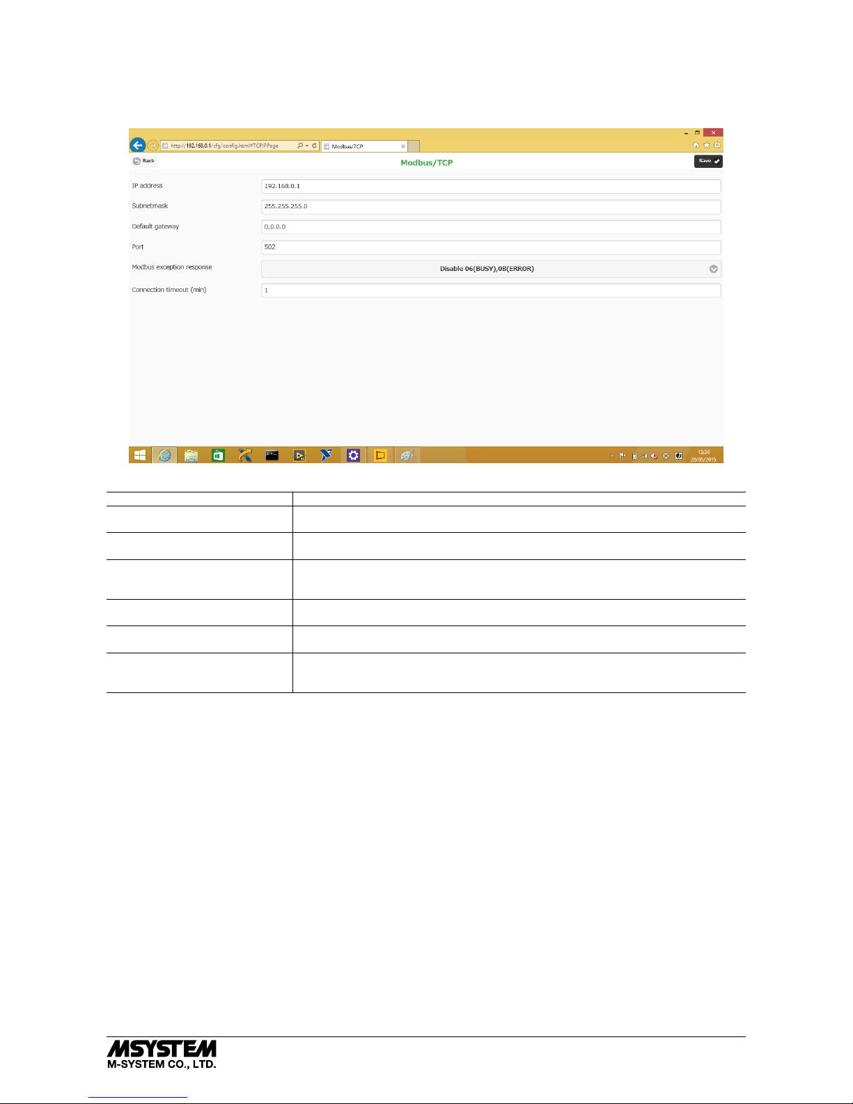
■ MODBUS/TCP CONFIGURATION
Configure the items for Modbus/TCP. After setting, clicking “Save” button on the upper right corner enables to save them in
the unit. Clicking “Back” button enables to return previous view before saving.
ITEM DESCRIPTION
IP address Set the IP address for the unit.
Range : 0.0.0.0 to 255.255.255.255
Subnetmask Set the Subnet Mask for the unit.
Range : 0.0.0.0 to 255.255.255.255
Default gateway Set the router address connected to external network. 0.0.0.0 (not used) is available for
local network, which does not communicate with external network.
Range : 0.0.0.0 to 255.255.255.255
Port Set the port number for Modbus/TCP.
Range : 0 to 65535
Modbus exception response Set if respond or not to exception code defined by Modbus.
Choose among not return 06 (BUSY), 0B (ERROR) and return 06 (BUSY), 0B (ERROR).
Connection timeout : (min) Set the time to cut off the connection when there are no transmission or receiving within
certain time from connection established.
Range : 1 to 60 minutes
Page 13

GR8-EM
5-2-55, Minamitsumori, Nishinari-ku, Osaka 557-0063 JAPAN
Phone: +81(6)6659-8201 Fax: +81(6)6659-8510 E-mail: info@m-system.co.jp
EM-8621 Rev.5 P. 13 / 15
■ MODBUS/RTU CONFIGURATION
Configure the items for Modbus/RTU. After setting, clicking “Save” button on the upper right corner enables to save them in
the unit. Clicking “Back” button enables to return previous view before saving.
ITEM DESCRIPTION
Transfer rate Set the transfer rate.
Choose among 2400, 4800, 9600, 19200, 38400, 57600 or 115200 bps.
Parity bit Set the parity bit. Choose among None, Odd or Even.
Stop bit Set the stop bit. Choose between 1 bit and 2 bits.
Read time out (ms) Set the time out for read out function (msec.).
Range : 10 to 10000 milli-seconds
Write time out (ms) Set the time out for write in function (msec.).
Range : 10 to 10000 milli-seconds
Cache function Set the use of cache.
Choose between Enable and Disable.
Inter-frame Interval (ms) Set the delay time from when response receiving till when transmitting next transmit
frame (msec.).
Range : 0 to 500 milli-seconds
Page 14

GR8-EM
5-2-55, Minamitsumori, Nishinari-ku, Osaka 557-0063 JAPAN
Phone: +81(6)6659-8201 Fax: +81(6)6659-8510 E-mail: info@m-system.co.jp
EM-8621 Rev.5 P. 14 / 15
■ DIAGNOSTICS INFORMATION
Device information and statistics of Modbus/TCP and Modbus/RTU are displayed.
■ DEVICE INFORMATION
ITEM DESCRIPTION
Model Model of the unit
Serial Serial number of the unit
Firmware version Firmware version of the unit
MAC address Ethernet MAC address of the unit
System up time Operating time from power on
■ Modbus/TCP STATISTICS
ITEM DESCRIPTION
Receive frames Received request numbers of Modbus/TCP
Error receive frames Numbers of error frame of received request
Transfer frames Numbers of transmitting response of Modbus/TCP
■ Modbus/RTU STATISTICS
EVENT LOG DESCRIPTION
Transfer frames Modbus/RTU request transmitting numbers to device
Receive frames Normal response receive numbers from device
(Including the case Modbus response is error response)
Error receive frames The numbers that response is error frame
Timeout receive frames The numbers of time out that there are no response
Page 15

GR8-EM
5-2-55, Minamitsumori, Nishinari-ku, Osaka 557-0063 JAPAN
Phone: +81(6)6659-8201 Fax: +81(6)6659-8510 E-mail: info@m-system.co.jp
EM-8621 Rev.5 P. 15 / 15
■ MAINTENANCE
Performing maintenance of the unit.
ITEM DESCRIPTION
Reboot the device Clicking “Reboot” enables to restart the unit
Update the firmware Firmware update is available in order to add new functions and improve operations.
Download the firmware from M-System web site. After browsing the file, clicking “Update” button enables to start the firmware update. Do not turn off the power while the
firmware update is proceeding.
 Loading...