

Page 1
FJR
P. 1 / 4 EM-1464 Rev.7
INSTRUCTION MANUAL
MODEL
FJR
RTD TRANSMITTER
(field-programmable)
COMPONENT IDENTIFICATION
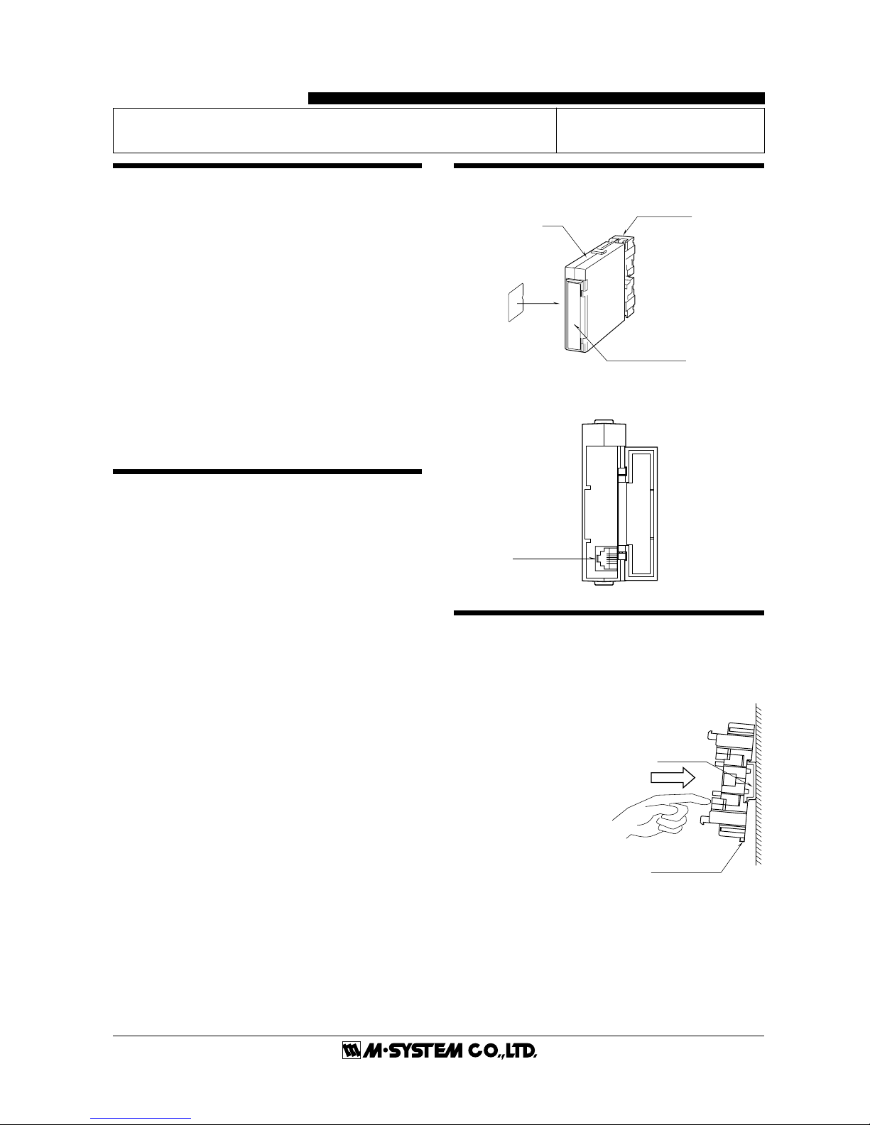
■ FRONT PANEL CONFIGURATIONS
INSTALLATION
Pull out the body in pressing the clamps located at the top and
bottom of the unit to separate it from the base socket.
■ DIN RAIL MOUNTING
Set the base socket so that its
DIN rail adapter is at the bottom. Hung the upper hook at
the rear side of base socket on
the DIN rail and push in the
lower. When removing the
socket, push down the DIN
rail adapter utilizing a minus
screwdriver and pull.
■ WALL MOUNTING
Refer to the drawings in the
following page.
DIN Rail
35mm wide
Spring Loaded
DIN Rail Adaptor
BEFORE USE ....
Thank you for choosing M-System. Before use, check the
contents of package you received as outlined below.
If you have any problems or questions with the product,
please contact M-System’s Sales Office or representatives.
■ PACKAGE INCLUDES:
Signal conditioner (body + base socket) ..................... (1)
■ MODEL NO.
Check that model No. described on specification label is
exactly what you ordered.
■ INSTRUCTION MANUAL
This manual describes necessary points of caution when you
use this product, installation and connection, hardware
setting, and basic maintenance procedures.
When you need to change software settings, please refer to
the Operation Manual for Model PU-2
❑ (EM-9255), Section
A.
POINTS OF CAUTION
■ POWER INPUT RATINGS
• Power input ratings are specified by the model number
suffix code. Check the power input voltage for the unit on the
specification label.
85 – 132V AC rating: 85 – 132V, 47 – 66 Hz, approx. 4.5VA
170 – 264V AC rating: 170 – 264V, 47 – 66 Hz, approx. 4.5VA
24V DC rating: 24 V ±10%, approx. 70mA
110V DC rating: 85 – 150V, approx. 20mA
■ REMOVING THE UNIT
• Before you remove the unit from its base socket or mount
it, turn off the power supply and input signal for safety.
■ ENVIRONMENT
• Indoor use
• When heavy dust or metal particles are present in the air,
install the unit inside proper housing with sufficient ventilation.
• Do not install the unit where it is subjected to continuous
vibration. Do not subject the unit to physical impact.
• Environmental temperature must be within -5 to +55°C (23
to 131°F) with relative humidity within 30 to 90% RH in
order to ensure adequate life span and operation.
■ WIRING
• Do not install cables (power supply, input and output) close
to noise sources (relay drive cable, high frequency line, etc.).
• Do not bind the unit's cables together with other cables
where high noise levels are present. Do not install them in
the same duct.
■ AND ....
• The unit is designed to function as soon as power is
supplied, however, a warm up for 10 minutes is required for
satisfying complete performance described in the data sheet.
Body
Base Socket
Specification Label
Connection
Diagram Label
(side)
Modular Jack
Page 2
FJR
P. 2 / 4 EM-1464 Rev.7
+
–
OUTPUT
5
6
U(+)
V(–)
POWER
7
8
PU-2
❑
MODULAR JACK
1
2
A
B
B
RTD
3
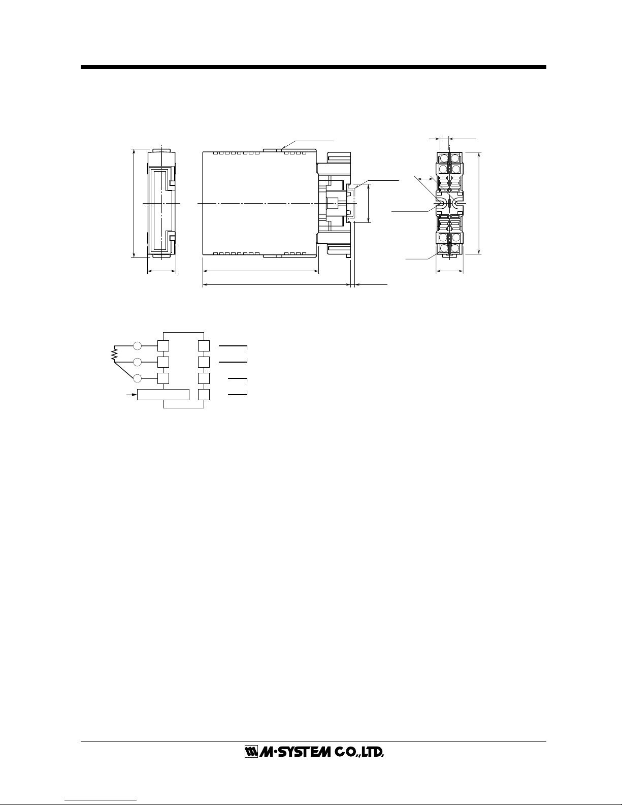
TERMINAL CONNECTIONS
Connect the unit as in the diagram below or refer to the connection diagram label on the unit side.
■ DIMENSIONS mm (inch)
■ CONNECTION DIAGRAM
12
34
768
5
26 (1.02)
93 (3.66)
15
(.59)
2–4.5 (.18)
HOLE
15 (.59) deep
8–M3.5
SCREW
7.8 (.31)
107 (4.21)
35.4 (1.39)
DIN RAIL
35mm wide
[3.3 (.13)]
CLAMP
(top & bottom)
137 (5.39)
•When mounting, no extra space is needed between units.
26 (1.02)
100 (3.94)
Page 3

FJR
P. 3 / 4 EM-1464 Rev.7
CHECKING
1) Terminal wiring: Check that all cables are correctly
connected according to the connection diagram.
2) Power input voltage: Check voltage across the terminal 7
–8 with a multimeter.
3) Input: Check that the input signal is within 0 – 100% of
the full-scale.
(With 20°C or 68°F, approx. 220mV with Pt 100Ω, approx.
110mV with Pt 50Ω.)
If RTD wires are broken, the output goes over 100% (below
0% with downscale protection) due to burnout protection
function. Check leadwires in such a case.
4) Output: Check that the load resistance meets the described specifications.
ADJUSTMENT PROCEDURE
This unit is calibrated at the factory to meet the ordered
specifications, therefore you usually do not need any calibration, unless you need to match the signal to a receiving
instrument or conduct regular calibration.
Zero and span are adjusted with using the Programming
Unit (model: PU-2
❑).
Refer to the Operation Manual for Model PU-2
❑ for explana-
tions how to use the programmer.
■ WARNING ON USE OF THE PROGRAMMING UNIT
• Be sure to disconnect the Programming Unit before you
turn on/off power supply to the unit.
■ HOW TO CALIBRATE THE OUTPUT SIGNAL
Use a signal source and measuring instruments of sufficient
accuracy level. Turn the power supply on and warm up for
more than 10 minutes.
• Fine Output Calibration
Using the Programming Unit (ITEM 19, 20)
ITEM 19 is for Zero, and ITEM 20 is for Span.
1) Turn the unit into Program mode (ITEM 01).
2) Apply simulated 0% input. Increase/decrease values (default: 0%) at ITEM 19 until the output signal is calibrated
to actual 0%.
3) Apply simulated 100% input. Increase/decrease value
(default: 100%) at ITEM 20 until the output signal is
calibrated to actual 100%.
4) Apply simulated 0% input again and check 0% output.
5) When 0% value is changed, repeat the above procedure 2)
- 4).
The 0% value may be shifted when the output span is
greater than the input span (gain ≥1).
Page 4

FJR
P. 4 / 4 EM-1464 Rev.7
MAINTENANCE
Regular calibration procedure is explained below:
■ CALIBRATION
Warm up the unit for at least 10 minutes. Apply 0%, 25%,
50%, 75% and 100% input signal. Check that the output
signal for the respective input signal remains within accuracy described in the data sheet. When the output is out of
tolerance, recalibrate the unit according to the "ADJUSTMENT PROCEDURE" explained earlier.
M-SYSTEM WARRANTY
M-System warrants such new M-System product which it manufactures to be free from defects in materials and workmanship during the 36-month period following the date that such
product was originally purchased if such product has been used under normal operating conditions and properly maintained, M-System's sole liability, and purchaser's exclusive remedies,
under this warranty are, at M-System's option, the repair, replacement or refund of the purchase price of any M-System product which is defective under the terms of this warranty. To
submit a claim under this warranty, the purchaser must return, at its expense, the defective M-System product to the below address together with a copy of its original sales invoice.
THIS IS THE ONLY WARRANTY APPLICABLE TO M-SYSTEM PRODUCT AND IS IN LIEU OF ALL OTHER WARRANTIES, EXPRESS OR IMPLIED, INCLUDING ANY IMPLIED
WARRANTIES OF MERCHANTABILITY OR FITNESS FOR A PARTICULAR PURPOSE. M-SYSTEM SHALL HAVE NO LIABILITY FOR CONSEQUENTIAL, INCIDENTAL OR
SPECIAL DAMAGES OF ANY KIND WHATSOEVER.
M-System Co., Ltd., 5-2-55, Minamitsumori, Nishinari-ku, Osaka 557-0063 JAPAN, Phone: (06) 6659-8201, Fax: (06) 6659-8510, E-mail: info@m-system.co.jp
[GROUP 01]
ITEM INPUT DATA EXAMPLE (DEFAULT) CONTENTS
01 S 0, 1 MTSW : MON MODE Modification code
0 : Data indication only.
1 : All parameters are modifiable.
02 P Alphanumeric TG : XXXXXXXXXX Tag name entry (10 characters max.)
03 P Number (%) OUTPER XXX.XX Output status monitor (%) & simulation output
04 D No input OUTTMP XXXX.XX Output temperature monitor (unit: ITEM 21)
05 D No input INPPER XXX.XX Input status monitor (%)
06 D No input INPVAL XXX.XX Input status monitor in Ω
10 TYPE OF RTD
P31RB-1: Pt 100 Pt 100
P32RB-2: JPt 100 JPt 100
D33RB-3: Pt 50 Pt 50
D34RB-4: Ni508.4 Ni 508.4
14 P Actual value SCLLOW XXXXXX Input range scaling 0% value (unit: ITEM 21)
15 P Actual value SCLHIG XXXXXX Input range scaling 100% value (unit: ITEM 21)
19 P Percentage FINZER Fine zero adjustment
Initial status shows actual bias (%).
When data is entered, output (%) is shown.
20 P Percentage FINSPN Fine span adjustment
Initial status shows actual gain (%).
When data is entered, output (%) is shown.
21 P TEMPERATURE UNIT
0 TMPSCL: [°C] °C Program ITEM 21 first before ITEM 14 when °F or K
1 TMPSCL: [°F] °F calibration is needed. This procedure is necessary whenever
2 TMPSCL: [K] K thermocouple type is changed.
Modification Code
D: No modification (writing) possible. Used only for monitoring (reading).
S: Modifiable at any time.
P: Modifiable only when the MAINTENANCE SWITCH is in the “PRG” mode.
PROGRAMMABLE ITEMS
The following items can be monitored and programmed. For detailed explanations, please refer to the Operation Manual for
Model PU-2
❑ (EM-9255), Section A.
MDF.
CODE
 Loading...