

Page 1
5-2-55, Minamitsumori, Nishinari-ku, Osaka 557-0063 JAPAN
Phone: +81(6)6659-8201 Fax: +81(6)6659-8510 E-mail: info@m-system.co.jp
EM-7691-A Rev.6 P. 1 / 4
INSTRUCTION MANUAL
WEB-ENABLED REMOTE TERMINAL UNIT
MODEL
DL8
BEFORE USE ....
Thank you for choosing M-System. Before use, please check
contents of the package you received as outlined below.
If you have any problems or questions with the product,
please contact M-System’s Sales Office or representatives.
■ PACKAGE INCLUDES:
Web-enabled remote terminal unit ....................................(1)
Protective cover ...................................................................(1)
Ferrite core (ZCAT 3035-1330 TDK) ..................................(1)
■ MODEL NO.
Confirm Model No. marking on the product to be exactly
what you ordered.
■ INSTRUCTION MANUAL
This manual describes necessary points of caution when
you use this product, including installation, connection and
basic maintenance procedures.
For detailed explanations to operate this product, please
refer to Users Manual (EM-7691-B), downloadable at MSystem’s web site: http://www.m-system.co.jp
POINTS OF CAUTION
■ CONFORMITY WITH EU DIRECTIVES
•The equipment must be mounted inside the instrument
panel of a metal enclosure.
•The actual installation environments such as panel configurations, connected devices, connected wires, may affect the protection level of this unit when it is integrated
in a panel system. The user may have to review the CE
requirements in regard to the whole system and employ
additional protective measures to ensure the CE conformity.
■ POWER INPUT RATING & OPERATIONAL RANGE
•Locate the power input rating marked on the product and
confirm its operational range as indicated below:
DC Power supply: Rated voltage 24V DC
24V DC ± 10%, approx. 12W
(@ internal power max. current 1.6 A)
Excitation supply (excitation for I/O module):
24V DC ± 10%, operational current 7A
(From power supply (exitation supply) connector, via con-
nector for internal bus, supplied to each I/O module. Power output current consumption must be under operational
current.)
■ GENERAL PRECAUTIONS
•Before you remove the unit or mount it, turn off the power
supply for safety.
■ ENVIRONMENT
•Indoor use.
•When heavy dust or metal particles are present in the
air, install the unit inside proper housing with sufficient
ventilation.
•Do not install the unit where it is subjected to continuous
vibration. Do not subject the unit to physical impact.
•Environmental temperature must be within -10 to +55°C
(14 to 131°F) with relative humidity within 30 to90% RH
in order to ensure adequate life span and operation.
■ WIRING
•Do not install cables close to noise sources (relay drive
cable, high frequency line, etc.).
•Do not bind these cables together with those in which
noises are present. Do not install them in the same duct.
•Use a ferrite core close to the unit for communication line.
Turn the cable twice (1 round) as figure below.
■ ABOUT SD CARDS
•Do NOT turn off the power of DL8 during writing data.
Insert or eject SD card according to the specified procedure.
•Confirm the front and back side of the SD card.
■ AND ....
•The unit is designed to function as soon as power is supplied, however, a warm up for 10 minutes is required for
satisfying complete performance described in the data
sheet.
INSTALLATION
Connection between DL8 series modules is done with the
connector of each module. Therefore, a base is not necessary. Since the connector between modules supplies power
and transfers internal communication data, do NOT change
modules during power supplied.
Hook
DIN Rail Adaptor
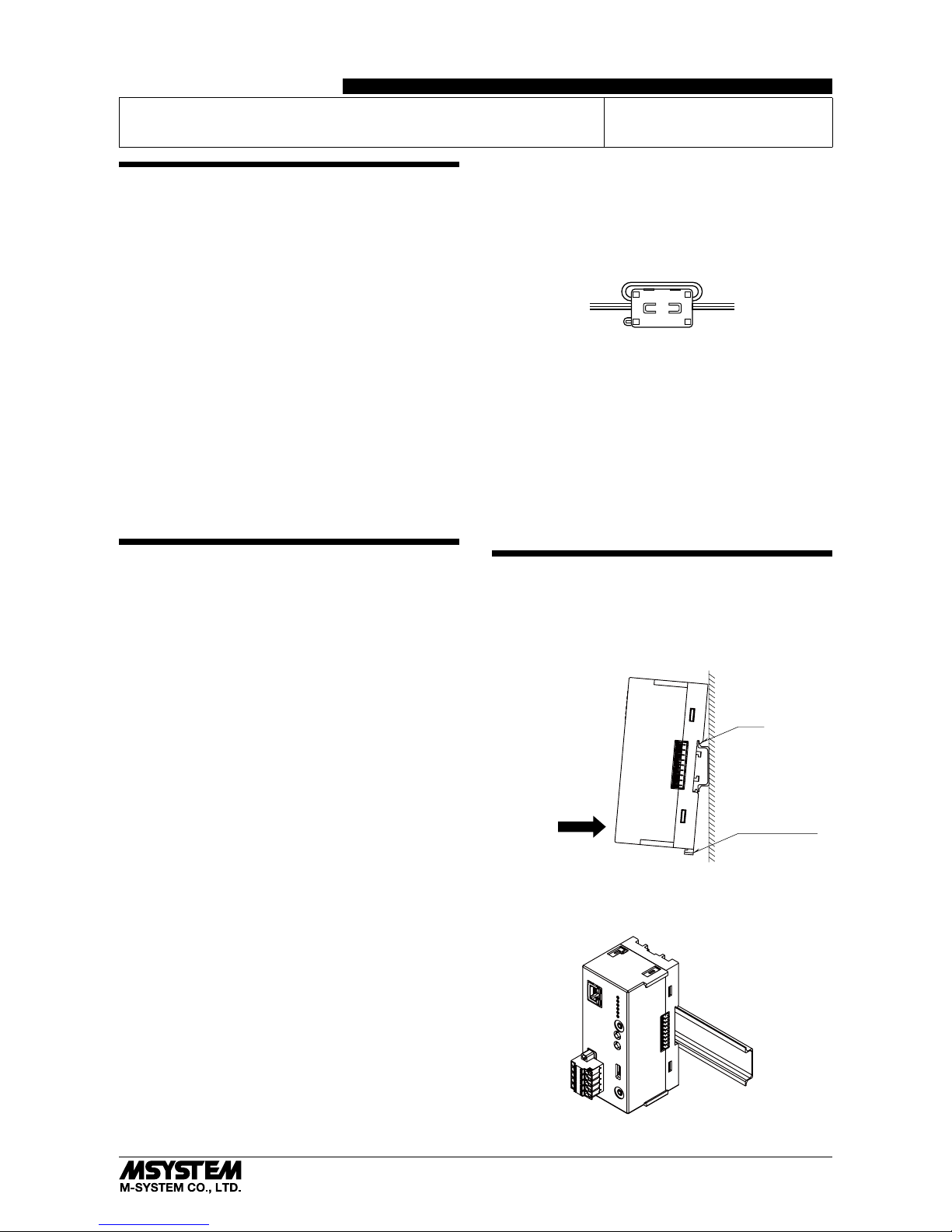
■ HOW TO MOUNT THE MODULE ON DIN RAIL
• Web-Enabled RTU Modules
Position the upper hook at the rear on the DIN rail and push in the lower.
When removing the module, push down the DIN rail adaptor utilizing a
minus screwdriver and pull.
Page 2
DL8
5-2-55, Minamitsumori, Nishinari-ku, Osaka 557-0063 JAPAN
Phone: +81(6)6659-8201 Fax: +81(6)6659-8510 E-mail: info@m-system.co.jp
EM-7691-A Rev.6 P. 2 / 4
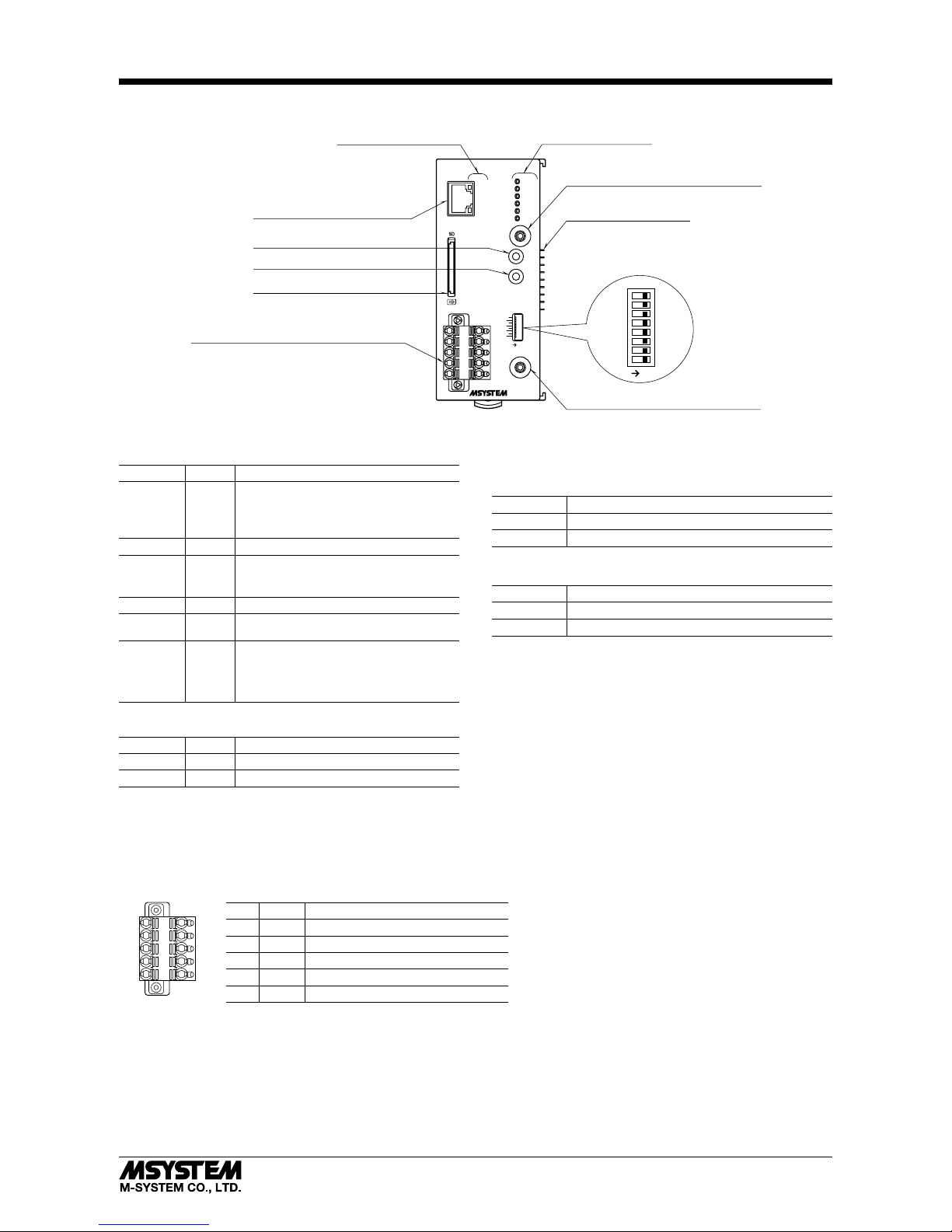
COMPONENT IDENTIFICATION
Status Indicator LED
Miniature Jack Connector for DLCFG
RJ-45 Connector for Ethernet
Logging Button (Type C & D)
SD Button (Type C & D)
SD Card Slot (Type C & D)
Miniature Jack Connector for R8CFG
Internal Bus Connector
DPLX
LNK
POWER
LOGGING
SD CARD
SEND
COM
ERROR
I/O
LOGGING
SD CARD
On
8
7
6
5
4
3
2
1
CFG
Function Setting DIP SW
8
7
6
5
4
3
2
1
On
Connector for Power Supply (Exc. supply),
RUN Contact Output
Ethernet Indicator LED
■ STATUS INDICATOR LED
LED Color Function
POWER Green
ON at device operating normally
Blinking at Ethernet LINK error
Blinking before obtaining DHCP address
LOGGING Green ON at logging (Type C & D)
SD CARD Green
ON during SD card mounted
Blinking at reading/writing SD card
(Type C & D)
SEND Green Blinking at e-mailing
COM Green
Blinking at communication
(except Modbus/TCP master)
ERROR Red
ON at error
•R8I/Omodulereadingerror
•SDcardaccesserror
•SDcardinsufficientcapacity
■ ETHERNET INDICATOR LED
LED Color Function
DPLX Amber ON at full duplex
LNK Green ON at link
■ POWER SUPPLY (EXC. SUPPLY), RUN CONTACT OUT-
PUT CONNECTOR TERMINAL ASSIGNMENT
Printed-circuit board connector (Phoenix Contact)
Unit side connector: MSTBV2,5/5-GF-5,08AU
Cable side connector: TFKC2,5/5-STF-5,08AU
■ POWER SUPPLY (EXC. SUPPLY), RUN CONTACT OUTPUT CONNECTOR TERMINAL ASSIGNMENT
Printed-circuit board connector (Phoenix Contact)
Unit side connector: MSTBV2,5/5-GF-5,08AU
Cable side connector: TFKC2,5/5-STF-5,08AU
No. ID FUNCTION
1 24V Power supply (exc. supply) 24 V DC
2 0V Power supply (exc. supply) 0 V DC
3 RUN RUN contact output
4 RUN RUN contact output
5 FE Power supply (exc. supply) earth
1
2
3
4
5
■ FRONT SWITCH
(*) Factory setting
•MINIATURE JACK for DLCFG (SW1)
SW1 FUNCTION
OFF (*) Set with DLCFG
ON FTP transfer and reporting e-mail reading
•REPORTING E-MAIL (SW2) *
1
SW2 E-MAIL OPERATON
OFF (*) Available
ON Not Available
*1. Type B, C and D only.
Note: Be sure to set unused SW3 through 8 to OFF.
■ LOGGING BUTTON
Pressing and holding 1 second starts and stops logging.
■ SD BUTTON
Pressing and holding for 4 seconds turns SD CARD LED off
and makes the card removable.
Page 3

DL8
5-2-55, Minamitsumori, Nishinari-ku, Osaka 557-0063 JAPAN
Phone: +81(6)6659-8201 Fax: +81(6)6659-8510 E-mail: info@m-system.co.jp
EM-7691-A Rev.6 P. 3 / 4
TERMINAL CONNECTION
Connect the unit as in the diagram below.
■ EXTERNAL DIMENSIONS unit: mm (inch)
•Unit
50 (1.97) [3 (.12)]
115 (4.53)[4 (.16)][7 (.28)]
55 (2.17)
73 (2.87)
DIN RAIL
(35 mm wide)
[4 (.16)]
•Protective Cover
5 (.20) 50 (1.97)
115 (4.53)
Page 4

DL8
5-2-55, Minamitsumori, Nishinari-ku, Osaka 557-0063 JAPAN
Phone: +81(6)6659-8201 Fax: +81(6)6659-8510 E-mail: info@m-system.co.jp
EM-7691-A Rev.6 P. 4 / 4
■ CONNECTION DIAGRAM
CONNECTOR
INTERNAL
POWER (5 V)
INTERNAL BUS
EXC. SUPPLY (24 V)
MINIATURE JACK
RJ-45 CONNECTOR
DLCFG
MINIATURE JACK
R8CFG
Ethenet
TERMINAL BLOCK
+24V
0V
FE
RUN
RUN CONTACT
OUTPUT
Note: In order to improve EMC performance, bond the FE
terminal to ground.
Caution: FE terminal is NOT a protective conductor terminal.
SD CARD SLOT
WIRING INSTRUCTIONS
■ Recommended solderless terminal
AI0,25-10YE 0.25 mm
2
(Phoenex Contact)
AI0,34-10TQ 0.34 mm
2
(Phoenex Contact)
AI0,5-10WH 0.5 mm
2
(Phoenex Contact)
AI0,75-10GY 0.75 mm
2
(Phoenex Contact)
AI1-10RD 1.0 mm
2
(Phoenex Contact)
AI1,5-10BK 1.5 mm
2
(Phoenex Contact)
AI2,5-10BU 2.5 mm
2
(Phoenex Contact)
Applicable wire size : 0.2 – 2.5 mm
2
Stripped length : 10 mm
 Loading...