

Page 1
CTH
P. 1 / 3 EM-1909 Rev.1
INSTRUCTION MANUAL
MODEL
CTH
CT TRANSMITTER
(inverter use)
■ WIRING
• Do not install cables (power supply, input and output) close
to noise sources (relay drive cable, high frequency line, etc.).
• Do not bind these cables together with those in which noises
are present. Do not install them in the same duct.
■ AND ....
• The unit is designed to function as soon as power is
supplied, however, a warm up for 10 minutes is required for
satisfying complete performance described in the data sheet.
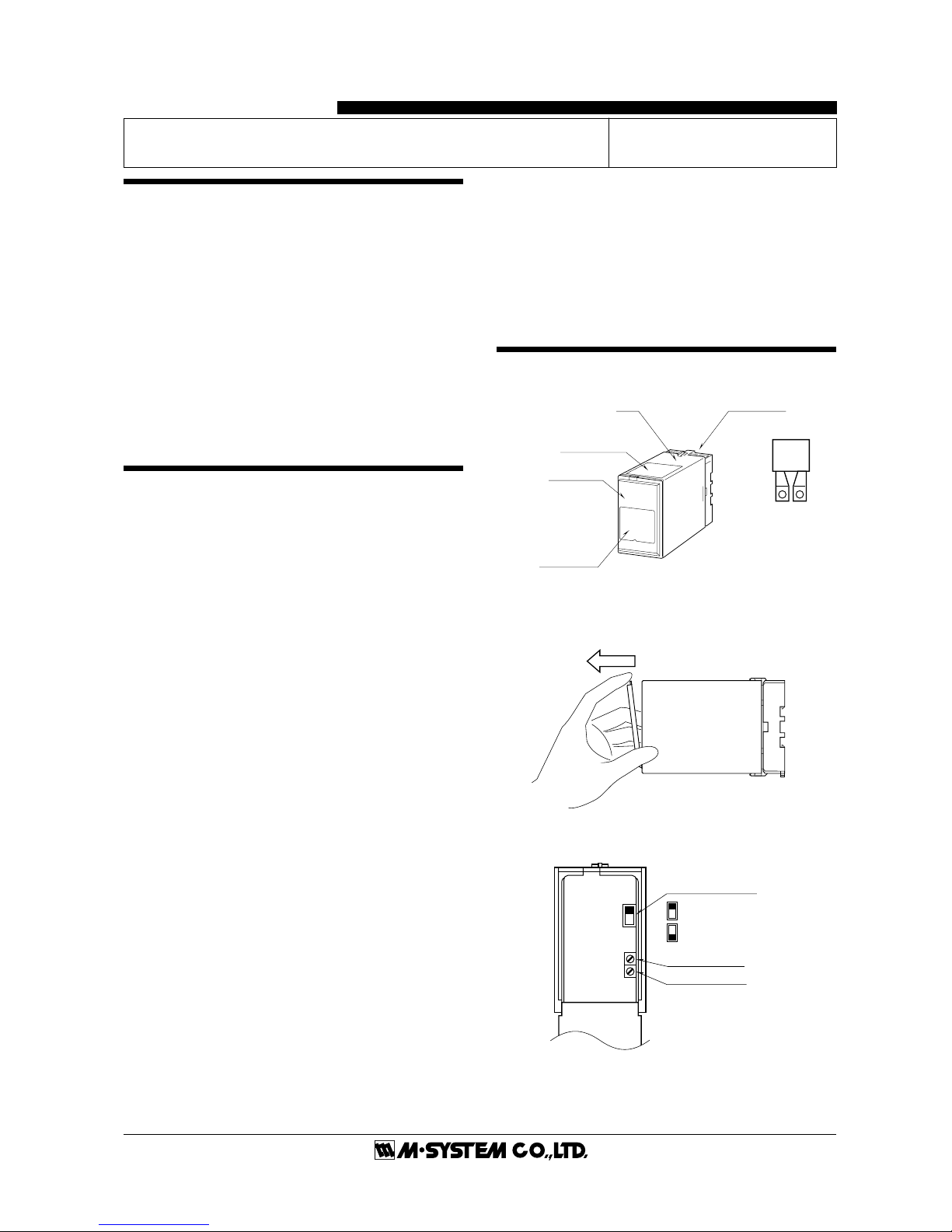
COMPONENT IDENTIFICATION
■ HOW TO OPEN THE FRONT COVER:
Position your finger on the hook at the top of front cover and
pull.
■ FRONT PANEL CONFIGURATIONS
The shape of base socket may be different
for some models.
BEFORE USE ....
Thank you for choosing M-System. Before use, check the
package you received as below.
If you have any problems or questions with the product,
please contact M-System's Sales Office or representatives.
■ PACKAGE INCLUDES:
Signal conditioner (body + base socket + CT protector) ..... (1)
■ MODEL NO.
Check that model No. described on specification label is
exactly what you ordered.
■ INSTRUCTION MANUAL
This manual describes necessary points of caution when you
use this product, installation, connection and basic maintenance procedures.
POINTS OF CAUTION
■ CONFORMITY WITH CE/LVD DIRECTIVE
(CE marking is unavailable for certain model suffix options.)
•␣ This equipment is suitable for use in Pollution Degree 2
environment and in Installation Category II, with the maximum operating voltage 300V.
Prior to installation, check that the insulation class of this
unit satisfies the system requirements.
• The equipment must be mounted inside a panel.
• The equipment must be installed such that appropriate
clearance and creepage distances are maintained to conform
to CE requirements. Failure to observe these requirements
may invalidate the CE conformance.
■ POWER INPUT RATINGS
• Power input ratings are specified by the model number
suffix code. Check the power input voltage for the unit on the
specification label.
AC power: rating ±10%, 50/60 ±2 Hz, approx. 2VA
DC power: rating ±10%, approx. 2W
(85 – 150V for 110V rating)
■ GENERAL
• Before you remove the unit from its base socket or mount it,
turn off the power supply and input signal for safety.
■ CT Protector
• Temperature of the CT Protector may rise if the signal
conditioner body is left unplugged from the base socket. Be
careful not to get burned when you need to touch it.
■ ENVIRONMENT
• Indoor use
• When heavy dust or metal particles are present in the air,
install the unit inside proper housing and ventilate it.
• Do not install the unit where it is subjected to continuous
vibration. Do not apply physical impact to the unit.
• Environmental temperature must be within -5 to +60°C (23
to 140°F) with relative humidity within 30 to 90% RH in order
to ensure adequate life span and operation.
CT Protector
Zero Adjustment
Input Filter Selector
(OFF)
(ON)
4 Hz – 200 kHz
4 Hz – 2 kHz
Span Adjustment
Body Base Socket
Connection
Diagram Label
Front Cover
Specification
Label
Page 2
CTH
P. 2 / 3 EM-1909 Rev.1
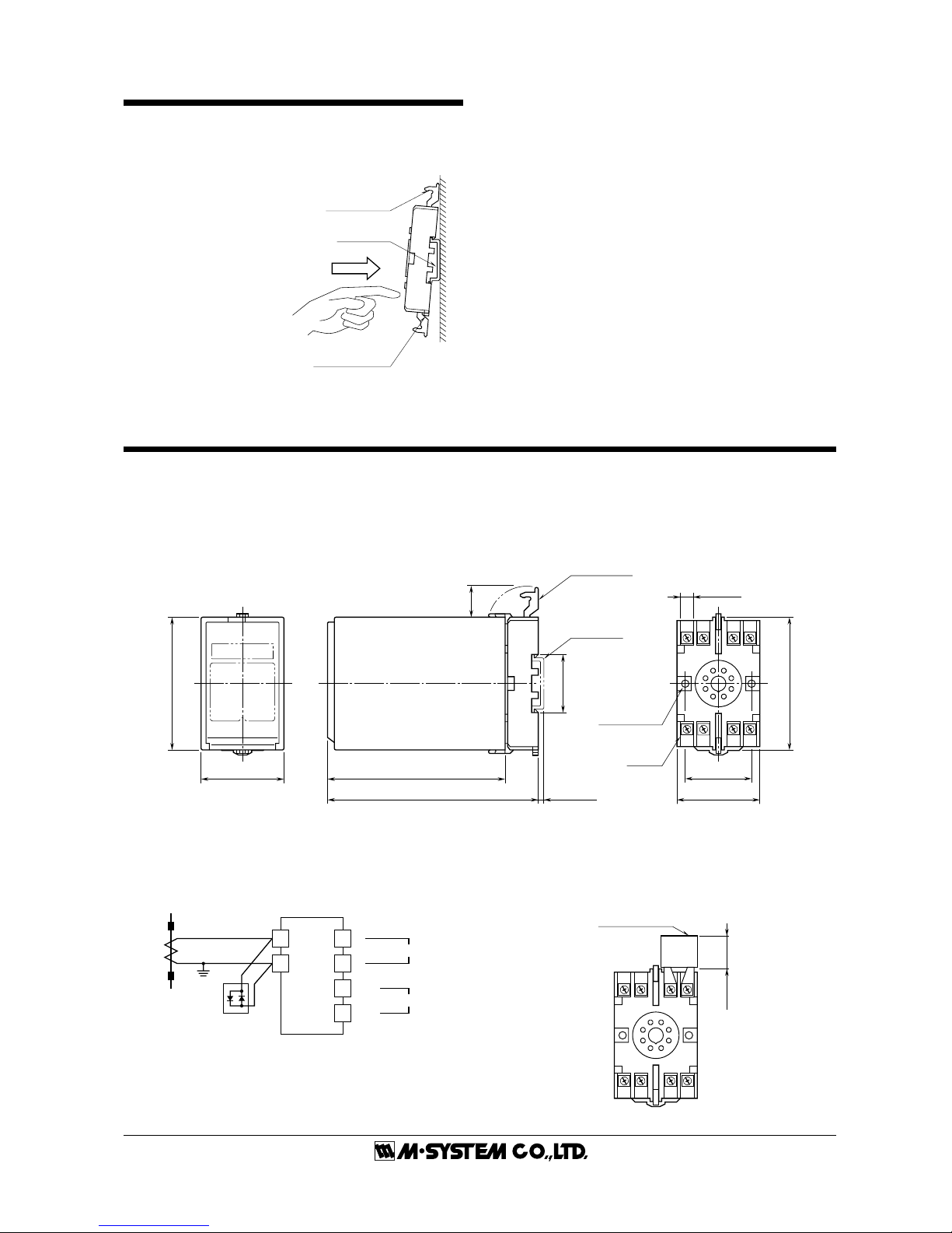
■ TERMINAL ASSIGNMENTS mm (inch)
■ DIMENSIONS mm (inch)
3456
2187
80 (3.15)
50 (1.97) 107 (4.21)
127 (5) [3.3 (.13)]
80 (3.15)
20
(.79)
35.4 (1.39)
40 (1.57)
50 (1.97)
7.8 (.31)
CLAMP
(top & bottom)
DIN RAIL
35mm wide
2–4.5 (.18) dia.
MTG HOLE
15 (.59) deep
8–M3.5
SCREW
•When mounting, no extra space is needed between units.
■ CONNECTION DIAGRAM
TERMINAL CONNECTIONS
Connect the unit as in the diagram below or refer to the connection diagram label on top of the unit.
Attach the CT Protector together with input wiring to the input screw terminals.
+
–
OUTPUT
1
U(+)
V(–)
POWER
7
8
2
LOAD
SOURCE
k
l
CT
L
K
CT PROTECTOR
model: CTM
3
4
56
2187
34
CT PROTECTOR
(model: CTM)
20 (.79)
Clamp
(top & bottom)
DIN Rail
35mm wide
Spring Loaded
DIN Rail Adaptor
Shape and size of the base socket
are slightly different with various
socket types.
INSTALLATION
Detach the yellow clamps located at the top and bottom of the
unit for separating the body from the base socket.
■ DIN RAIL MOUNTING
Set the base socket so that
its DIN rail adaptor is at the
bottom. Position the upper
hook at the rear side of base
socket on the DIN rail and
push in the lower. When
removing the socket, push
down the DIN rail adaptor
utilizing a screwdriver (–)
and pull.
■ WALL MOUNTING
Refer to the drawings in the
following page.
Page 3

CTH
P. 3 / 3 EM-1909 Rev.1
CHECKING
1) Terminal wiring: Check that all cables are correctly
connected according to the connection diagram.
2) Power input voltage: Check voltage across the terminal 7
–␣ 8 with a multimeter.
3) Input: Check that the input signal is within 0 – 100% of
the full-scale.
Be sure to short the secondary side of CT or turn off the
current at its primary side for preventing the CT from
burning when the cables are to be disconnected from input
terminals of the base socket.
4) Output: Check that the load resistance meets the described specifications.
ADJUSTMENT PROCEDURE
This unit is calibrated at the factory to meet the ordered
specifications, therefore you usually do not need any calibration.
For matching the signal to a receiving instrument or in case
of regular calibration, adjust the output as explained in the
following.
■ HOW TO CALIBRATE THE OUTPUT SIGNAL
Use a signal source and measuring instruments of sufficient
accuracy level. Turn the power supply on and warm up for
more than 10 minutes.
1) ZERO: Apply 0% input and adjust output to 0%.
2) SPAN: Apply 100% input and adjust output to 100%.
3) Check ZERO adjustment again with 0% input.
4) When ZERO value is changed, repeat the above procedure
1) – 3).
MAINTENANCE
Regular calibration procedure is explained below:
■ CALIBRATION
Warm up the unit for at least 10 minutes. Apply 0%, 25%,
50%, 75% and 100% input signal. Check that the output
signal for the respective input signal remains within accuracy described in the data sheet. When the output is out of
tolerance, recalibrate the unit according to the "ADJUSTMENT PROCEDURE" explained earlier.
M-SYSTEM WARRANTY
M-System warrants such new M-System product which it manufactures to be free from defects in materials and workmanship during the 36-month period following the date that such
product was originally purchased if such product has been used under normal operating conditions and properly maintained, M-System's sole liability, and purchaser's exclusive remedies,
under this warranty are, at M-System's option, the repair, replacement or refund of the purchase price of any M-System product which is defective under the terms of this warranty. To
submit a claim under this warranty, the purchaser must return, at its expense, the defective M-System product to the below address together with a copy of its original sales invoice.
THIS IS THE ONLY WARRANTY APPLICABLE TO M-SYSTEM PRODUCT AND IS IN LIEU OF ALL OTHER WARRANTIES, EXPRESS OR IMPLIED, INCLUDING ANY IMPLIED
WARRANTIES OF MERCHANTABILITY OR FITNESS FOR A PARTICULAR PURPOSE. M-SYSTEM SHALL HAVE NO LIABILITY FOR CONSEQUENTIAL, INCIDENTAL OR
SPECIAL DAMAGES OF ANY KIND WHATSOEVER.
M-System Co., Ltd., 5-2-55, Minamitsumori, Nishinari-ku, Osaka 557-0063 JAPAN, Phone: (06) 6659-8201, Fax: (06) 6659-8510, E-mail: info@m-system.co.jp
 Loading...