

Page 1
INSTRUCTION MANUAL
CLAMP-ON PULSE SENSOR
BEFORE USE ....
Thank you for choosing M-System. Before use, please check
contents of the package you received as outlined below.
If you have any problems or questions with the product,
please contact M-System’s Sales Office or representatives.
■ PACKAGE INCLUDES:
Clamp-on pulse sensor ........................................................(1)
■ MODEL NO.
Confirm Model No. marking on the product to be exactly
what you ordered.
■ INSTRUCTION MANUAL
This manual describes necessary points of caution when
you use this product, including installation, connection and
basic maintenance procedures.
POINTS OF CAUTION
■ POWER INPUT RATING & OPERATIONAL RANGE
•Locate the power input rating marked on the product and
confirm its operational range as indicated below:
12V DC rating: 12V ±10%, max. 5mA
■ GENERAL PRECAUTIONS
•Before you remove the module or mount it, turn off the
power supply and input signal for safety.
■ ENVIRONMENT
•Indoor use.
•When heavy dust or metal particles are present in the air,
install the module inside proper housing with sufficient
ventilation.
•Do not install the module where it is subjected to continuous vibration. Do not subject the unit to physical impact.
•Environmental temperature must be within 0 to 55°C (32
to 131°F) with relative humidity within 80% RH in order
to ensure adequate life span and operation.
MODEL
CLSP
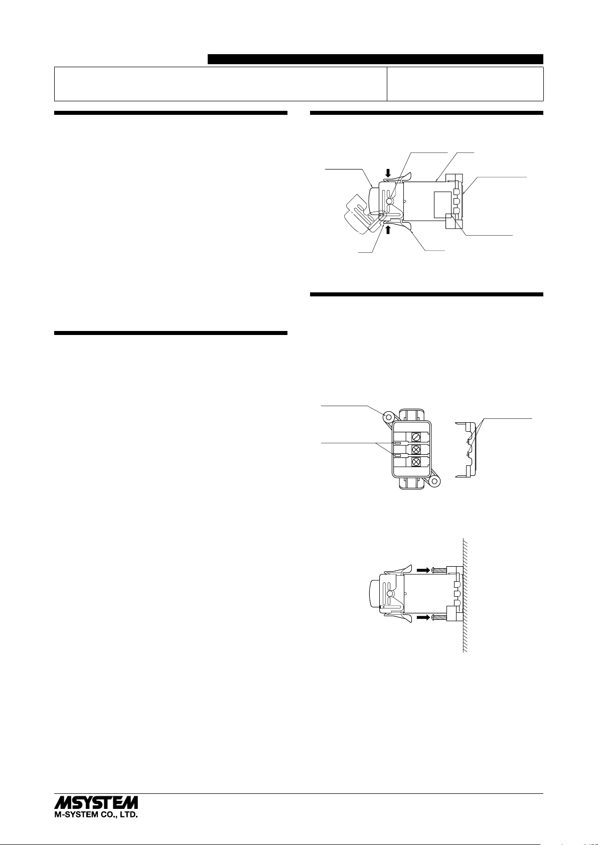
COMPONENT IDENTIFICATION
BodyInput Cable
Top Section
*
*
Tab
*Binding strap here
Lever
Terminal Cover
(separable)
Specifications
INSTALLATION
■ MOUNTING THE MODULE
1) Remove the terminal cover and connect wires according
to the connection diagram. Be aware of the wire insertion direction (See ‘Inserting Wires’).
2) Put the terminal cover back so that its keys meet the key
holes. Be aware of the cover direction.
Mounting Hole
Terminal Cover
Key Hole
3) Tighten screws using the mounting holes to fix the module on a wall.
12V
R0
R1
Terminal Cover
Key
■ WIRING
•Do not install cables close to noise sources (relay drive
cable, high frequency line, etc.).
•Do not bind these cables together with those in which
noises are present. Do not install them in the same duct.
■ AND ....
•The module is designed to function as soon as power is
supplied, however, a warm up for 10 minutes is required
for satisfying complete performance described in the data
sheet.
5-2-55, Minamitsumori, Nishinari-ku, Osaka 557-0063 JAPAN
Phone: +81(6)6659-8201 Fax: +81(6)6659-8510 E-mail: info@m-system.co.jp
■ CONNECTING THE INPUT CABLE
1) Squeeze the levers on both sides to detach the tabs and
pull out the top section.
2) Place the input cable to the position indicated on the
above drawing.
3) Put back the top section and bind over the tabs/levers
with a binding strap.
EM-9237 Rev.3 P. 1 / 2
Page 2

TERMINAL CONNECTIONS
Connect the unit as in the diagram below.
■ EXTERNAL DIMENSIONS unit: mm (inch)
33 (1.30)
39 (1.54)
49.1 (1.93)
2–3.5 dia. MTG HOLE
5 (.20) dia.
CLSP
TERMINAL COVER
3–M3 SCREW
12V
R0
R1
22 (.87)
28 (1.10)
34 (1.34)
■ CONNECTION DIAGRAM
PULSE INPUT
+
CLSP
12V
R0
R1
+
PULSE OUTPUT
–
POWER SUPPLY
WIRING INSTRUCTIONS
■ SOLDERLESS TERMINAL unit: mm (inch)
Refer to the drawing below for recommended ring tongue
terminal size. Spade tongue type is also applicable. Solderless terminals with insulation sleeve do not fit.
Applicable wire size: 0.3 – 0.75 mm
3 (.12) max.
4 min.
(.16)
2
3.2 (.13) dia.
14
79 (3.11)
(.55)
CHECKING
1) Terminal wiring: Check that all cables are correctly connected according to the connection diagram.
2) Power input voltage: Check voltage across the terminal
12V – R0 with a multimeter.
3) Input: Check the input signal.
4) Output: Check the output signal.
(.24)
6 max.
12 (.47) max.
■ INSERTING WIRES
Insert the output and power supply wires from the direction
as shown below and tighten firmly (torque 0.5 N·m).
12V
R0
R1
5-2-55, Minamitsumori, Nishinari-ku, Osaka 557-0063 JAPAN
Phone: +81(6)6659-8201 Fax: +81(6)6659-8510 E-mail: info@m-system.co.jp
LIGHTNING SURGE PROTECTION
M-System offers a series of lightning surge protector for
protection against induced lightning surges. Please contact
M-System to choose appropriate models.
EM-9237 Rev.3 P. 2 / 2
 Loading...