

Page 1
INSTRUCTION MANUAL
SIGNAL TRANSMITTER
(single- and dual-channel output loop powered isolator)
•Do not install the unit where it is subjected to continuous
BEFORE USE ....
Thank you for choosing M-System. Before use, please check
contents of the package you received as outlined below.
If you have any problems or questions with the product,
please contact M-System’s Sales Office or representatives.
■ PACKAGE INCLUDES:
Signal conditioner ...............................................................(1)
■ MODEL NO.
Confirm Model No. marking on the product to be exactly
what you ordered.
■ INSTRUCTION MANUAL
This manual describes necessary points of caution when
you use this product, including installation, connection and
basic maintenance procedures.
POINTS OF CAUTION
■ CONFORMITY WITH UL
•This equipment is suitable for use in a Pollution Degree
2 environment.
•This equipment is to be used with the maximum operating voltage 30 V rms and 42.4 V peak or 60 V DC.
•The equipment musts be mounted inside a suitable fire
enclosure.
•Operating temperature: -40 to +55°C (-40 to +131°F)
•Altitude up to 2000 meters.
■ CONFORMITY WITH EU DIRECTIVES
•Functional insulation is maintained between the input
and output.
•The input voltage across the terminals must be 70 V or
less.
•The equipment must be mounted inside a panel.
•Insert noise filters for the power source, input and output
connected to the unit. COSEL Model NAC-04-472, TDK
Model ZCAT 3035-1330 or equivalent is recommended.
•The actual installation environments such as panel configurations, connected devices, connected wires, may affect the protection level of this unit when it is integrated
in a panel system. The user may have to review the CE
requirements in regard to the whole system and employ
additional protective measures to ensure the CE conformity.
•Install lightning surge protectors for those wires connected to remote locations.
vibration. Do not subject the unit to physical impact.
•Environmental temperature must be within -40 to +85°C
(-40 to +185°F) with relative humidity within 0 to 95%
RH in order to ensure adequate life span and operation.
•Be sure that the ventilation slits are not covered with cables, etc.
■ WIRING
•Do not install cables close to noise sources (relay drive
cable, high frequency line, etc.).
•Do not bind these cables together with those in which
noises are present. Do not install them in the same duct.
■ AND ....
•The unit is designed to function as soon as power is supplied, however, a warm up for 10 minutes is required for
satisfying complete performance described in the data
sheet.
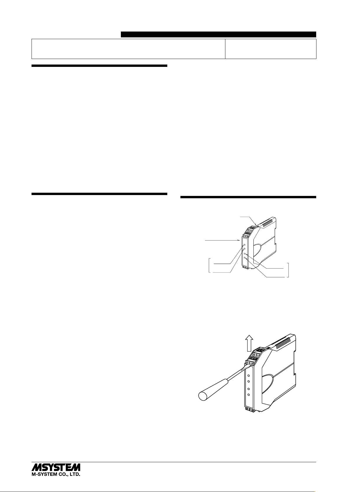
COMPONENT IDENTIFICATION
■ HOW TO SEPARATE THE EURO TYPE CONNECTOR
TERMINAL BLOCKS
When you need to separate the euro type connector terminal blocks from the transmitter body for wiring, insert a minus driver between the euro type connector terminal block
and the housing body, pull up the driver and pull out the
euro type connector terminal block.
Specifications
(side)
Ch. 1
Zero Adj.
Span Adj.
MODEL
Body
B3VS/2
B3VS/1
Zero Adj.
Span Adj.
Ch. 2
■ GENERAL PRECAUTION
•Before you remove the unit or mount it, turn off the power
supply and input signal for safety.
■ ENVIRONMENT
•Indoor use.
•When heavy dust or metal particles are present in the
air, install the unit inside proper housing with sufficient
ventilation.
5-2-55, Minamitsumori, Nishinari-ku, Osaka 557-0063 JAPAN
Phone: +81(6)6659-8201 Fax: +81(6)6659-8510 E-mail: info@m-system.co.jp
EM-7523 Rev.5 P. 1 / 3
Page 2
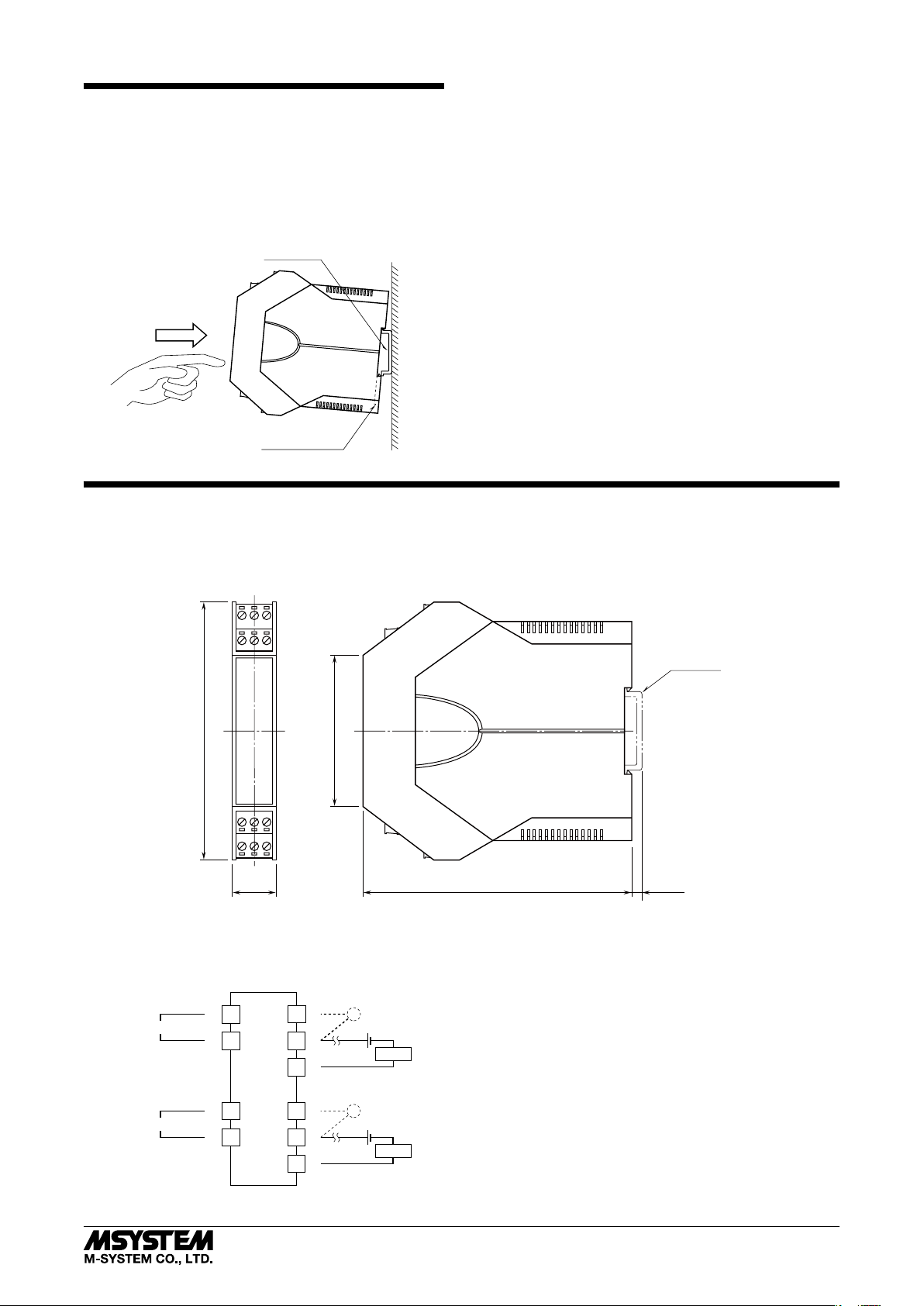
INSTALLATION
■ DIN RAIL MOUNTING
Set the unit so that its DIN rail adaptor is at the bottom.
Position the upper hook at the rear side of the unit on the
DIN rail and push in the lower. When removing the unit,
push down the DIN rail adaptor utilizing a minus screwdriver and pull.
DIN Rail
35mm wide
Spring Loaded
DIN Rail Adaptor
TERMINAL CONNECTIONS
Connect the unit as in the diagram below or refer to the connection diagram on the side of the unit.
B3VS/2 / B3VS/1
■ EXTERNAL DIMENSIONS unit: mm (inch)
10 11 12
789
106 (4.17)
123
456
62 (2.44)
18 (.71) 110.5 (4.35)
■ CONNECTION DIAGRAM
MONITOR
Ch.1 INPUT
Ch.2 INPUT
+
7
–
8
+
1
–
2
–
12
+
10
Ch.1 OUTPUT
–
11
4 – 20 mA DC
–
6
+
4
Ch.2 OUTPUT
–
5
4 – 20 m ADC
MONITOR
*
mA
24 V DC
mA
24 V DC
DIN RAIL
35mm wide
[5 (.20)]
• When mounting, no extra space is needed between units.
LOAD
LOAD
* DC ammeter’s internal resistance 10 ohms max.
5-2-55, Minamitsumori, Nishinari-ku, Osaka 557-0063 JAPAN
Phone: +81(6)6659-8201 Fax: +81(6)6659-8510 E-mail: info@m-system.co.jp
EM-7523 Rev.5 P. 2 / 3
Page 3

■ WIRING INSTRUCTIONS
•Applicable wire size
2
Solid: 0.2 to 2.5 mm
Stranded: 0.2 to 2.5 mm
(0.55 to 1.75 dia.)
2
(Tinning wire ends may cause
contact failure and therefore is not recommended.)
Ferruled: 0.2 to 1.5 mm
2
(0.55 to 1.35 dia.)
The following Phoenix Contact terminals are
recommended:
AI 0,25-8YE 0.2 to 0.25 mm
AI 0,34-8TQ 0.25 to 0.34 mm
AI 0,5-8WH 0.34 to 0.5 mm
AI 0,75-8GY 0.5 to 0.75 mm
AI 1,0-8RD 0.75 to 1.0 mm
AI 1,5-8BK 1.0 to 1.5 mm
2
2
2
2
2
2
•Expose wire conductors by 8 mm (0.31”).
Wire exposure Recommended
4 mm dia.
max.
ferruled wire
4 mm dia.
max.
B3VS/2 / B3VS/1
ADJUSTMENT PROCEDURE
This unit is calibrated at the factory to meet the ordered
specifications, therefore you usually do not need any calibration.
For matching the signal to a receiving instrument or in case
of regular calibration, adjust the output as explained in the
following.
■ HOW TO CALIBRATE THE OUTPUT SIGNAL
Use a signal source and measuring instruments of sufficient
accuracy level. Turn the power supply on and warm up for
more than 10 minutes.
1) ZERO: Apply 0% input and adjust output to 0%.
2) SPAN: Apply 100% input and adjust output to 100%.
3) Check ZERO adjustment again with 0% input.
4) When ZERO value is changed, repeat the above procedure 1) – 3).
8 mm 8 mm
CHECKING
1) Terminal wiring: Check that all cables are correctly connected according to the connection diagram.
2) Input: Check that the input voltage is within 0 – 100% of
full-scale.
3) Output: Check that the load is within the permissible
limit including wiring resistance.
Load Resistance (Ω) =
(including leadwire resistance)
4) When you check the output signal, connect an ammeter
of which the internal resistance is of 10 Ω max. to the
monitor terminals.
Supply Voltage (V) – 12 (V)
0.02 (A)
MAINTENANCE
Regular calibration procedure is explained below:
■ CALIBRATION
Warm up the unit for at least 10 minutes. Apply 0%, 25%,
50%, 75% and 100% input signal. Check that the output
signal for the respective input signal remains within accuracy described in the data sheet. When the output is out of
tolerance, recalibrate the unit according to the “ADJUSTMENT PROCEDURE” explained earlier.
LIGHTNING SURGE PROTECTION
M-System offers a series of lightning surge protector for
protection against induced lightning surges. Please contact
M-System to choose appropriate models.
5-2-55, Minamitsumori, Nishinari-ku, Osaka 557-0063 JAPAN
Phone: +81(6)6659-8201 Fax: +81(6)6659-8510 E-mail: info@m-system.co.jp
EM-7523 Rev.5 P. 3 / 3
 Loading...