

AS4T
5-2-55, Minamitsumori, Nishinari-ku, Osaka 557-0063 JAPAN
Phone: +81(6)6659-8201 Fax: +81(6)6659-8510 E-mail: info@m-system.co.jp
EM-1608 Rev.12 P. 1 / 5
THERMOCOUPLE ALARM
(dual or quad alarm trip; eld-congurable)
MODEL
AS4T
INSTRUCTION MANUAL
BEFORE USE ....
Thank you for choosing M-System. Before use, please check
contents of the package you received as outlined below.
If you have any problems or questions with the product,
please contact M-System’s Sales Office or representatives.
This equipment is for use in general industrial environments, therefore may not be suitable for applications which
require higher level of safety (e.g. safety or accident prevention systems)or of reliability (e.g. vehicle control or combustion control systems).
For safety, installation and maintenance of this equipment
must be conducted by qualified personnel.
■ PACKAGE INCLUDES:
Signal conditioner
(body + base socket + CJC sensor) ................................. (1)
■ MODEL NO.
Confirm that the model number described on the product is
exactly what you ordered.
■ INSTRUCTION MANUAL
This manual describes necessary points of caution when
you use this product, including installation, connection and
basic maintenance procedures.
■ SYMBOLS USED ON THE PRODUCT AND IN THIS MANUAL
The symbol indicated on the equipment, means that
the user must refer to the related parts in the manual for
safe operation of the equipment. It is essential to read the
instructions wherever the symbol appears in the manual.
WARNING: is reserved for conditions and actions that
can cause serious or fatal injury.
CAUTION : is reserved for conditions and actions that can
cause injury or instrument damage.
WARNING
■ INSULATION CLASS
Basic insulation (Signal input or output to Power input: 300
V) is maintained.
If insulation failure may result in equipment, hazardous
voltage (maximum 240 V) may result to signal input and
then electric shock may cause.
Prior to installation, prepare supplemental insulation
(equivalent basic insulation) between signal input and external circuits.
CAUTION
■ REGARDING SAFETY
If equipment is not used in a manner not specified by MSystem, the protection provided by the equipment may be
impaired.
■ CONFORMITY WITH LOW VOLTAGE DIRECTIVE OR UL
•This equipment is suitable for use in a Pollution Degree
2 environment and in Installation Category II (transient
voltage 2500 V).
•Altitude up to 2000 meters.
•The equipment must be mounted inside a panel.
•The equipment must be installed such that appropriate
clearance and creepage distances are maintained to conform to EU/UL requirements. Failure to observe these
requirements may invalidate the EU/UL conformance.
■ CONFORMITY WITH EMC DIRECTIVE
•Insert a noise filter for the power source connected to the
unit. TDK-Lambda Noise Filter Model RSNA-2006 or
equivalent is recommended.
•The actual installation environments such as panel configurations, connected devices, connected wires, may affect
the protection level of this unit when it is integrated in a
panel system. The user may have to review the CE requirements in regard to the whole system and employ additional protective measures to ensure the CE conformity.
■ SIGNAL INPUT
This terminal is used for signal input.
Do not connect or measure to the circuits including transient voltage 2500 V.
Refer to “INPUT SPECIFICATIONS” in detail.
■ OUTPUT TERMINAL
Never use the output terminal under any load that exceeds
the rated values. Otherwise it will impair prescribed performance and cause burning of the equipment itself.
■ WIRING
•For wiring connection, refer to “TERMINAL CONNECTIONS” and wire correctly. Fire, electric shock and failure cause if wire are incorrectly connected.
•Wire using vinyl insulated power cable that meet input
voltage and load current for equipment and screw by an
adequate torque.
Loose screws may abnormally generate heat and fire
may cause. (Proper tightening torque [N·m] : 0.98 – 1.18)
•Do not install cables close to noise sources (relay drive
cable, high frequency line, etc.).
•Do not bind these cables together with those in which
noises are present. Do not install them in the same duct.
AS4T
5-2-55, Minamitsumori, Nishinari-ku, Osaka 557-0063 JAPAN
Phone: +81(6)6659-8201 Fax: +81(6)6659-8510 E-mail: info@m-system.co.jp
EM-1608 Rev.12 P. 2 / 5
POINTS OF CAUTION
■ POWER INPUT RATING & OPERATIONAL RANGE
Locate the power input rating marked on the product and
confirm its operational range as indicated below:
■ AC Power
M2: 100 – 240 V AC, 50 – 60 Hz, maximum 6 VA
(85 – 264 V AC, 47 – 66 Hz)
■ DC Power
R: 24 V DC (24 V ±10%), maximum 3.5 W
P: 110 V DC (85 – 150 V), maximum 3.5 W
■ GENERAL PRECAUTIONS
Before you remove the unit from its base socket or mount it,
turn off the power supply and input signal for safety.
■ ENVIRONMENT
•Indoor use
•When heavy dust or metal particles are present in the
air, install the unit inside proper housing with sufficient
ventilation.
•Do not install the unit where it is subjected to continuous
vibration. Do not subject the unit to physical impact.
•Environmental temperature must be within -5 to +55°C
(23 to 131°F) with relative humidity within 30 to 90% RH
in order to ensure adequate life span and operation.
■ AND ....
•The unit is designed to function as soon as power is supplied, however, a warm up for 10 minutes is required for
satisfying complete performance described in the data
sheet.
•Never use the internal relay under any load that exceeds
the rated contact values including the switching capacities (contact voltage and contact current).
Otherwise it will impair prescribed performance (insulation failure, contact welding, contact failure) and cause
burning of the Relay itself.
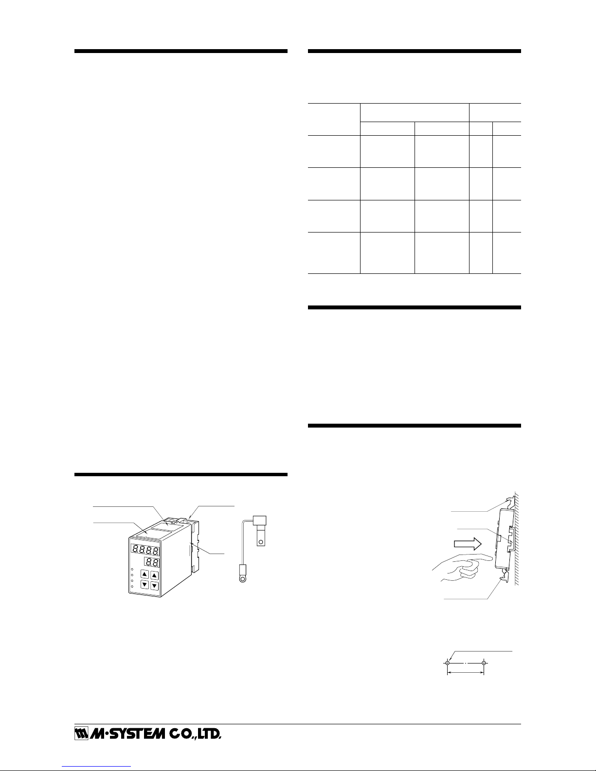
COMPONENT IDENTIFICATION
Body
Specifications
Base Socket
Connection Diagram
CJC
Sensor
INPUT SPECIFICATIONS
Input resistance: 1 MΩ min.
Burnout sensing: 45 nA ±10%
Default setting: K (CA) -100.0 – +999.9°C
T/C
USABLE RANGE
CONFORMANCE
LIMIT
°C °F °C °F
(PR) *
K (CA) *
E (CRC) *
-52 to +1860
-272 to +1472
-272 to +1020
-61.6 to +3380
-458 to +2682
-458 to +1868
150
-200
-200
302
-328
-328
J (IC)
T (CC) *
B (RH) *
-260 to +1300
-272 to +500
24 to 1920
-436 to +2372
-458 to +932
75.2 to 3488
-260
-200
450
-436
-328
842
R *
S *
C
(WRe 5-26)
-100 to +1860
-100 to +1860
-52 to +2416
-148 to +3380
-148 to +3380
-61.6 to +4381
150
150
-52
302
302
-61.6
N
U
L
P
(Platinel II)
-272 to +1400
-252 to +600
-252 to +1000
-52 to +1496
-458 to +2552
-422 to +1112
-422 to +1832
-61.6 to +2725
-200
-252
-252
-52
-328
-422
-422
-61.6
* For temperatures ranges near the lower limit of the usable range, the
transmitter may not satisfy the described accuracy.
OUTPUT SPECIFICATIONS
■ Quad Alarm
Relay rating: 120 V AC @ 1 A (cos ø = 1)
240 V AC @ 0.5 A (cos ø = 1)
30 V DC @ 1 A (resistive load)
■ Dual Alarm
Relay rating: 120 V AC @ 5 A (cos ø = 1)
240 V AC @ 2.5 A (cos ø = 1)
30 V DC @ 5 A (resistive load)
INSTALLATION
Detach the yellow clamps located at the top and bottom of
the unit to separate the body from the base socket.
■
Clamp
(top & bottom)
DIN Rail
35mm wide
Spring Loaded
DIN Rail Adaptor
Shape and size of the base socket
are slightly different with various
socket types.
DIN RAIL MOUNTING
Set the base socket so that its
DIN rail adaptor is at the bottom. Position the upper hook at
the rear side of base socket on the
DIN rail and push in the lower.
When removing the socket, push
down the DIN rail adaptor utilizing a minus screwdriver and pull.
■
2-M4or4.5(.18)dia.hole
40±0.2
MOUNTING HOLES
(TOP VIEW)
WALL MOUNTING
•Install using M4 screw with referring to the right dimension.
•Install by screw that is securely
fastened or equivalent means.

AS4T
5-2-55, Minamitsumori, Nishinari-ku, Osaka 557-0063 JAPAN
Phone: +81(6)6659-8201 Fax: +81(6)6659-8510 E-mail: info@m-system.co.jp
EM-1608 Rev.12 P. 3 / 5
FRONT VIEW & PROGRAMMING
■
L1
L2
L3
L4
ALARM
DATA
ITEM
DATA
ITEM
ITEM No. Display
DATA UP-DOWN Keys
ITEM No. UP-DOWN Keys
*Monitor LEDs
DATA Display
*L3 or L4 does not turn on for dual output type.
PROGRAMMING PROCEDURE
1 ) Press ITEM UP or DOWN key until ITEM display indicates “01”.
2 ) Press DATA UP or DOWN key and choose “1” or “2” on DATA
display.
1 : Only alarm setpoints are modifiable.
2 : All parameters are modifiable.
3 ) Press ITEM UP or DOWN key until ITEM display shows the
ITEM No. you need to change.
4 ) Press DATA UP or DOWN key and choose a DATA No. or value
you need on DATA display.
5 ) Repeat above 3 and 4. (Entered data is stored when you move to
a new ITEM.)
6 ) Press ITEM UP or DOWN key until ITEM display indicates “01”.
7 ) Press DATA UP or DOWN key and choose “0” on the display.
8 ) Press ITEM UP or DOWN key until ITEM display indicates “P”.
DATA display shows process input.
(You can now check data setting by choosing ITEM No.)
Note: DO NOT press UP and DOWN keys simultaneously.
ITEM
MDF.
CODE
DATA
CONTENTS DEFAULT SETTING
P N/A -272 – 2416*
1
Process input display in engineering unit ----
L1
L2
L3
L4
1, 2
1, 2
1, 2
1, 2
-272 – 2416*
1
-272 – 2416*
1
-272 – 2416*
1
-272 – 2416*
1
L1 alarm setpoint in engineering unit
L2 alarm setpoint in engineering unit
L3 alarm setpoint in engineering unit *
2
L4 alarm setpoint in engineering unit *
2
Quad: 20.0
Quad: 30.0
Quad: 70.0
Quad: 80.0
Dual: 20.0
Dual: 80.0
01 0, 1, 2 Modification code
0 : Data indication only.
1 : Only ITEM L1 – L4 are modifiable.
2 : All parameters are modifiable.
1
02 N/A 00 – 99 Status indication (“0” is normally indicated.)
0: Normal 1: Memory error 10: Out of input range -15 – +115%
03 N/A 3 Input type 3: Thermocouple
04 2 0 – 99 Power ON-delay time (seconds) 5
05 2 0 – 99 Alarm ON-delay time (seconds) 0
06 2 0, 1, 2, 3 , 4 Moving average (sampling cycle: 100 msec.)
0: No, 1: 4 samples, 2: 8 samples, 3: 16 samples, 4: 32 samples
0
07
08
09
10
2
2
2
2
0, 1
0, 1
0, 1
0, 1
L1 trip operation
L2 trip operation
L3 trip operation
L4 trip operation
(0: Lo, 1: Hi)
(0: Lo, 1: Hi)
(0: Lo, 1: Hi) *
2
(0: Lo, 1: Hi) *
2
Quad: 0
Quad: 0
Quad: 1
Quad: 1
Dual: 0
Dual: 1
11 2 -1, 0, 1 – 60 Power-saving mode
-1 : Continuous display upon startup
0 : Continuous display after the last access
1 – 60: Time before display turned off (minutes)
10
12
13
14
15
2
2
2
2
0, 1
0, 1
0, 1
0, 1
L1 coil at alarm (0: Energized, 1: De-energized)
L2 coil at alarm (0: Energized, 1: De-energized)
L3 coil at alarm (0: Energized, 1: De-energized)*
2
L4 coil at alarm (0: Energized, 1: De-energized)*
2
0
0
0
0
16 N/A ---- Version No. indication ----
17
18
19
20
2
2
2
2
0.0 – 2416
0.0 – 2416
0.0 – 2416
0.0 – 2416
L1 hysteresis (deadband) in engineering unit
L2 hysteresis (deadband) in engineering unit
L3 hysteresis (deadband) in engineering unit *
2
L4 hysteresis (deadband) in engineering unit *
2
1.0
1.0
1.0
1.0
21 2 0, 1 Burnout (0: Downscale, 1: Upscale) 1
22 2 -272 – 2416*
1
Upper range temperature limit
Display blinking with higher temperature
999.9
PV blinking at upscale burnout

AS4T
5-2-55, Minamitsumori, Nishinari-ku, Osaka 557-0063 JAPAN
Phone: +81(6)6659-8201 Fax: +81(6)6659-8510 E-mail: info@m-system.co.jp
EM-1608 Rev.12 P. 4 / 5
ITEM
MDF.
CODE
DATA
CONTENTS DEFAULT SETTING
23 2 -272 – 2416*
1
Lower range temperature limit
Display blinking with lower temperature
-100.0
PV blinking at downscale
burnout
24 2 0, 1, 2 Temperature unit (0: °C, 1: °F, 2: K) 0
25 2 0 – 12 Thermocouple type
0: (PR), 1: K (CA), 2: E (CRC), 3: J (IC), 4: T (CC), 5: B (RH)
6: R, 7: S, 8: C (WRe 5-26), 9: N, 10: U, 11: L, 12: P (Platinel II)
1: K (CA)
*1. It operates simultaneously with the display unit of ITEM 24. Refer to the table 1 for available setting range.
*2. Quad alarm trip type only
Table 1: USABLE RANGE
T/C
USABLE RANGE
°C °F K
(PR) *
1
-52.0 – +1860 -61.6 – +3380 221.2 – 2133
K (CA) *
1
-272 – +1472 -458 – +2682 1.2 – 1745
E (CRC) *
1
-272 – +1020 -458 – +1868 1.2 – 1293
J (IC) -260 – +1300 -436 – +2372 13.2 – 1573
T (CC) *
1
-272 – +500.0 -458 – +932.0 1.2 – 773.2
B (RH) *
1
24.0 – 1920 75.2 – 3488 297.2 – 2193
R *
1
-100.0 – +1860 -148.0 – +3380 173.2 – 2133
S *
1
-100.0 – +1860 -148.0 – +3380 173.2 – 2133
C (WRe 5-26) -52.0 – +2416 -61.6 – +4381 221.2 – 2689
N *
1
-272 – +1400 -458 – +2552 1.2 – 1673
U -252 – +600.0 -422 – +1112 21.2 – 873.2
L -252 – +1000 -422 – +1832 21.2 – 1273
P (Platinel II) -52.0 – +1496 -61.6 – +2725 221.2 – 1769
*1. For temperatures ranges near the lower limit of the usable range, the transmitter may not satisfy the described accuracy.
*2. Minimum step
-199.9 to 999.9: 0.1
Not greater than -200, not lower than 1000: 1
CONNECTIONS
■ EXTERNAL DIMENSIONS unit: mm (inch)
• When mounting, no extra space is needed between units.
5678
21
1110
80 (3.15)
40 (1.57)
50 (1.97)
7.8 (.31)
2–4.5 (.18) dia.
MTG HOLE
25 (.98) deep
11
–
M3.5
SCREW
39
4
For wiring connection, refer to “TERMINAL CONNECTIONS” and wire correctly.
Fire, electric shock and failure cause if wire are incorrectly connected.
80 (3.15)
50 (1.97) 103 (4.06)
132 (5.20)
20
(.79)
[3.3 (.13)]
35.4 (1.39)
CLAMP
(top & bottom)
DIN RAIL
35mm wide
■ TERMINAL ASSIGN
78
21
1110
39
7 (.28)
CJC SENSOR
(model: CJM)
5
4
6

AS4T
5-2-55, Minamitsumori, Nishinari-ku, Osaka 557-0063 JAPAN
Phone: +81(6)6659-8201 Fax: +81(6)6659-8510 E-mail: info@m-system.co.jp
EM-1608 Rev.12 P. 5 / 5
TERMINAL CONNECTIONS
Connect the unit as in the diagram below or refer to the connection diagram on top of the unit.
Attach the CJC sensor together with input wiring to the
input terminals. The CJC sensor is not interchangeable.
Check that its serial number is the same as that of the unit.
U(+)
V(–)
POWER
7
8
10
11
9
2
3
1
L2 OUTPUT
L1 OUTPUT
N.C.
N.O.
COM
N.C.
N.O.
COM
■ SPDT RELAY
U(+)
V(–)
POWER
7
8
10
11
9
2
3
1
L4 OUTPUT
L1 OUTPUT
COM
L3 OUTPUT
L2 OUTPUT
COM
■ N.O. RELAY ■ N.C. RELAY
10
11
9
2
3
1
L4 OUTPUT
L1 OUTPUT
COM
L3 OUTPUT
L2 OUTPUT
COM
+
–
T / C
CJC
SENSOR
metal leg
model: CJM
comp. leadwire
5
4
6
+
–
+
–
T / C
CJC
SENSOR
metal leg
comp. leadwire
5
4
6
+
–
CHECKING
1 ) Terminal wiring: Check that all cables are correctly
connected according to the connection diagram.
2 ) Power input voltage: Check voltage across the termi-
nal 7 – 8 with a multimeter.
3 ) Input: Check across the terminals 5 – 6 with a sensi-
tive voltmeter to show a normal emf voltage value.
If the thermocouple or its extension wires are broken,
the PV display indicates the upper range temperature
limit and blinks (the lower range limit with downscale)
due to burnout function. Check leadwires in such a
case.
4 ) Alarm operations: Check the alarm operations refer-
ring to the figure below.
5 ) Output load: Check that the output rating road is: 240
V AC / 120 VA or 30 V DC / 30 W (240 V AC / 600 VA
or 30 V DC / 150 W for dual alarm, Output Code 5) at
the maximum. For maximum relay life with inductive
load, external protection is recommended.
050 100
Input
(%)
LL LHHH
L2 (1–2)
ON
L3 (1–3)
ON
L4 (9–11)
ON
OFF
OFF
L1 (9–10)
ON
OFF
OFF
Alarm Trip Operation Terminal No. in parentheses
Example with quad N.O. contacts (LL, L, H, HH)
Trip Operation in Power Failure
• Output code 2: All relays turn off.
• Output code 3: All relays turn on.
• Output code 5: Terminals 1 –3, 9 – 11 turn on.
MAINTENANCE
Regular calibration procedure is explained below:
■ CALIBRATION
Warm up the unit for at least 10 minutes.
• H (HH) Setpoint
Increase the input signal from a value lower than the setpoint and check that the relay trips at the H (or HH) setpoint within the setpoint accuracy described in the data
sheet.
• L (LL) Setpoint
Decrease the input signal from a value higher than the setpoint and check that the relay trips at the L (or LL) setpoint
within the setpoint accuracy described in the data sheet.
When the setpoints are shifted, please contact M-System’s
Sales Office or representatives.
LIGHTNING SURGE PROTECTION
In order to protect the unit from lightning surges entering
through power supply cables, use of appropriate lightning
surge protectors are recommended. Please contact M-System.
 Loading...