

Page 1
AS4CT
P. 1 / 4
EM-1603 Rev.6
5-2-55, Minamitsumori, Nishinari-ku, Osaka 557-0063 JAPAN
Phone: +81(6)6659-8201 Fax: +81(6)6659-8510 E-mail: info@m-system.co.jp
CT ALARM
(dual or quad alarm trip; eld-congurable)
MODEL
AS4CT
INSTRUCTION MANUAL
BEFORE USE ....
Thank you for choosing M-System. Before use, please check
contents of the package you received as outlined below.
If you have any problems or questions with the product,
please contact M-System’s Sales Office or representatives.
■ PACKAGE INCLUDES:
Signal conditioner (body + base socket + CT protector)
...... (1)
■ MODEL NO.
Confirm that the model number described on the product is
exactly what you ordered.
■ INSTRUCTION MANUAL
This manual describes necessary points of caution when
you use this product, including installation, connection and
basic maintenance procedures.
POINTS OF CAUTION
■ CONFORMITY WITH EU DIRECTIVES
•This equipment is suitable for use in a Pollution Degree
2 environment and in Measurement Category II (input,
output), Installation Category II (power input). Basic insulation (signal input to output to power input: 300 V)is
maintained. Prior to installation, check that the insulation class of this unit satisfies the system requirements.
•Altitude up to 2000 meters.
•The equipment must be mounted inside a panel.
•Insert a noise filter for the power source connected to the
unit. TDK-Lambda Noise Filter Model RSNA-2006 or
equivalent is recommended.
•The equipment must be installed such that appropriate
clearance and creepage distances are maintained to conform to CE requirements. Failure to observe these requirements may invalidate the CE conformance.
•The actual installation environments such as panel configurations, connected devices, connected wires, may affect
the protection level of this unit when it is integrated in
a panel system. The user may have to review the CE requirements in regard to the whole system and employ additional protective measures to ensure the CE conformity.
■ POWER INPUT RATING & OPERATIONAL RANGE
•Locate the power input rating marked on the product and
confirm its operational range as indicated below:
100 – 240 V AC rating: 85 – 264 V, 47 – 66 Hz,
4.6 VA @ 100 V AC
5.9 VA @ 200 V AC
6.8 VA @ 264 V AC
24 V DC rating: 24 V ±10%, approx. 3.5 W
110 V DC rating: 85 – 150 V, approx. 3.5 W
■ GENERAL PRECAUTIONS
•Before you remove the unit from its base socket or mount
it, turn off the power supply and input signal for safety.
■ ENVIRONMENT
•Indoor use
•When heavy dust or metal particles are present in the
air, install the unit inside proper housing with sufficient
ventilation.
•Do not install the unit where it is subjected to continuous
vibration. Do not subject the unit to physical impact.
•Environmental temperature must be within -5 to +55°C
(23 to 131°F) with relative humidity within 30 to 90% RH
in order to ensure adequate life span and operation.
■ WIRING
•Do not install cables close to noise sources (relay drive
cable, high frequency line, etc.).
•Do not bind these cables together with those in which
noises are present. Do not install them in the same duct.
■ AND ....
•The unit is designed to function as soon as power is supplied, however, a warm up for 10 minutes is required for
satisfying complete performance described in the data
sheet.
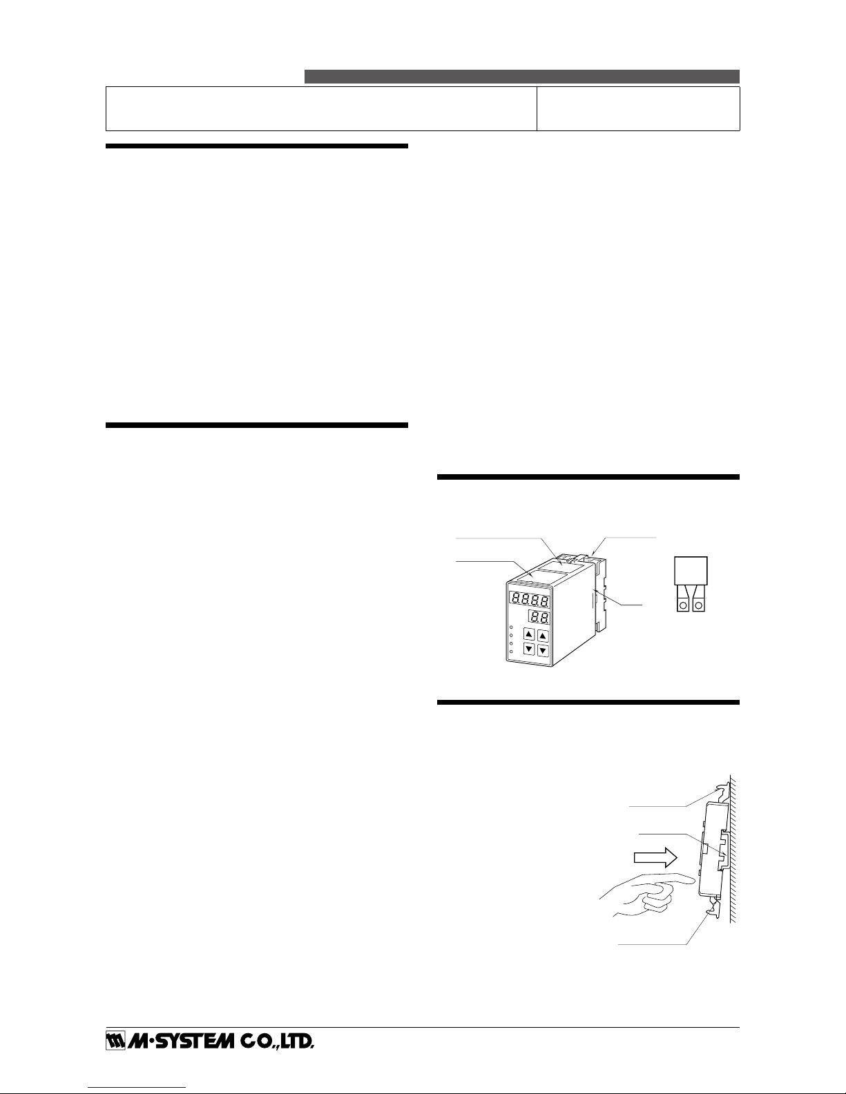
COMPONENT IDENTIFICATION
INSTALLATION
Detach the yellow clamps located at the top and bottom of
the unit to separate the body from the base socket.
■ DIN RAIL MOUNTING
Set the base socket so that its
DIN rail adaptor is at the bottom. Position the upper hook
at the rear side of base socket
on the DIN rail and push in
the lower. When removing
the socket, push down the
DIN rail adaptor utilizing a
minus screwdriver and pull.
■ WALL MOUNTING
Refer to “EXTERNAL DIMENSIONS.”
Body
Specifications
Base Socket
Connection Diagram
Clamp
(top & bottom)
DIN Rail
35mm wide
Spring Loaded
DIN Rail Adaptor
Shape and size of the base socket
are slightly different with various
socket types.
CT Protector
Page 2
AS4CT
P. 2 / 4
EM-1603 Rev.6
5-2-55, Minamitsumori, Nishinari-ku, Osaka 557-0063 JAPAN
Phone: +81(6)6659-8201 Fax: +81(6)6659-8510 E-mail: info@m-system.co.jp
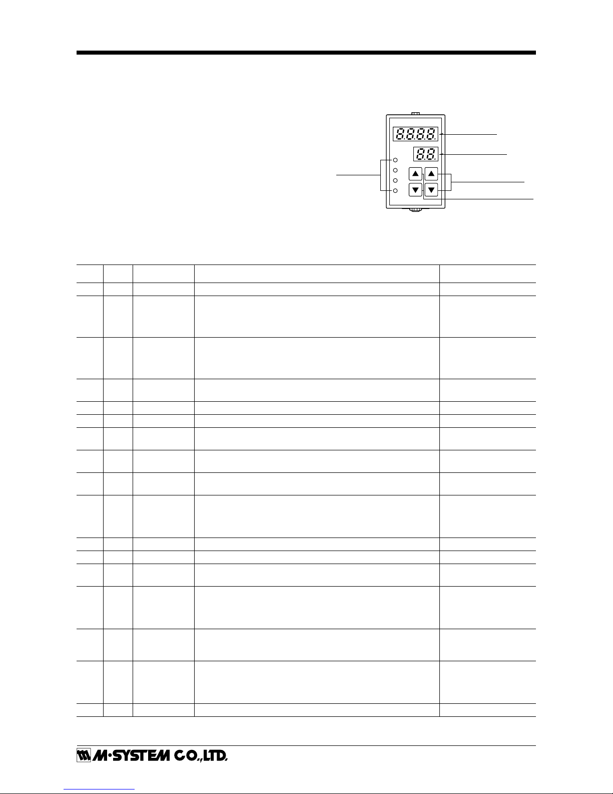
FRONT VIEW & PROGRAMMING
■ PROGRAMMING PROCEDURE
1) Press ITEM UP or DOWN key until ITEM display indicates
“01”.
2) Press DATA UP or DOWN key and choose “1” or “2” on DATA
display.
1 : Only alarm setpoints are modifiable.
2 : All parameters are modifiable.
3) Press ITEM UP or DOWN key until ITEM display shows the
ITEM No. you need to change.
4) Press DATA UP or DOWN key and choose a DATA No. or value
you need on DATA display.
5) Repeat above 3 and 4. (Entered data is stored when you move
to a new ITEM.)
6) Press ITEM UP or DOWN key until ITEM display indicates
“01”.
7) Press DATA UP or DOWN key and choose “0” on the display.
8) Press ITEM UP or DOWN key until ITEM display indicates
“P”. DATA display shows process input.
(You can now check data setting by choosing ITEM No.)
Note: DO NOT press UP and DOWN keys simultaneously.
L1
L2
L3
L4
ALARM
DATA
ITEM
DATA
ITEM
ITEM No. Display
DATA UP-DOWN Keys
ITEM No. UP-DOWN Keys
*Monitor LEDs
DATA Display
*L3 or L4 does not turn on for dual output type.
ITEM
MDF.
CODE
DATA CONTENTS DEFAULT SETTING
P N/A -1999 – 9999 Process input display in engineering unit (as set in ITEM 07/08) ----
L1
L2
L3
L4
1, 2
1, 2
1, 2
1, 2
-1999 – 9999
*
1
-1999 – 9999
*
1
-1999 – 9999
*
1
-1999 – 9999
*
1
L1 alarm setpoint in engineering unit
L2 alarm setpoint in engineering unit
L3 alarm setpoint in engineering unit
*
2
L4 alarm setpoint in engineering unit *
2
Quad: 20.0
Quad: 30.0
Quad: 70.0
Quad: 80.0
Dual: 20.0
Dual: 80.0
01 0, 1, 2 Modification code
0 : Data indication only.
1 : Only ITEM L1 – L4 are modifiable.
2 : All parameters are modifiable.
1
02 N/A 0 – 99
Status indication (“0” is normally indicated.)
0: Normal 1: Memory error 10: Out of input range -15 – +115%
03 N/A 6, 7 Input range 6: S1, 7: S5 Specified when ordering
04 N/A -15.0 – 115.0 Input indicated in % (as set in ITEM27, 28) ----
05
06
22-19.99 – 99.99
0.000 – 9.999
Zero adjustment (%) (fine adj. of the value set in ITEM 27)
Gain adjustment (fine adj. of the value set in ITEM 28)
0.00
1.000
07 2 -1999 – 9999 Display range scaling 0%
of the range set in ITEM 27/28. ITEM 07 < ITEM 08
0.0
08 2 -1999 – 9999 Display range scaling 100%
of the range set in ITEM 27/28. ITEM 07 < ITEM 08
100.0
09 2 0, 1, 2, 3
Decimal point position
(Specify the number of digits)
0 : _ _ _ _
1 : _ _ _ . _
2 : _ _ . _ _
3 : _ . _ _ _
1
10 2 0 – 99 Power ON-delay time (seconds) 5
11 2 0 – 99 Alarm ON-delay time (seconds) 0
12 2 0, 1, 2, 3, 4
Moving average (sampling cycle: 100 msec.)
0: No, 1: 4 samples, 2: 8 samples, 3: 16 samples, 4: 32 samples
0
13
14
15
16
2
2
2
2
0, 1
0, 1
0, 1
0, 1
L1 trip operation
L2 trip operation
L3 trip operation
L4 trip operation
(0: Lo, 1: Hi)
(0: Lo, 1: Hi)
(0: Lo, 1: Hi) *
2
(0: Lo, 1: Hi) *
2
Quad: 0
Quad: 0
Quad: 1
Quad: 1
Dual: 0
Dual: 1
17 2 0, 1 – 60 Power-saving mode
0 : Continuous display after the last access*
3
1 – 60 : Time before display turned off (minutes)
10
18
19
20
21
2
2
2
2
0, 1
0, 1
0, 1
0, 1
L1 coil at alarm (0: Energized, 1: De-energized)
L2 coil at alarm (0: Energized, 1: De-energized)
L3 coil at alarm (0: Energized, 1: De-energized)*
2
L4 coil at alarm (0: Energized, 1: De-energized)*
2
0
0
0
0
22 N/A ---- Version No. indication ----
Page 3

AS4CT
P. 3 / 4
EM-1603 Rev.6
5-2-55, Minamitsumori, Nishinari-ku, Osaka 557-0063 JAPAN
Phone: +81(6)6659-8201 Fax: +81(6)6659-8510 E-mail: info@m-system.co.jp
TERMINAL CONNECTIONS
Connect the unit as in the diagram below or refer to the connection diagram on top of the unit.
Attach the CT Protector together with input wiring to the
input screw terminals.
LOAD
k
l
CT
L
K
CT PROTECTOR
model: CTM
LOAD
k
l
CT
L
K
CT PROTECTOR
model: CTM
U(+)
V(–)
POWER
7
8
10
11
9
2
3
1
L2 OUTPUT
L1 OUTPUT
N.C.
N.O.
COM
N.C.
N.O.
COM
■ SPDT RELAY
U(+)
V(–)
POWER
7
8
10
11
9
2
3
1
L4 OUTPUT
L1 OUTPUT
COM
L3 OUTPUT
L2 OUTPUT
COM
■ N.O. RELAY ■ N.C. RELAY
10
11
9
2
3
1
L4 OUTPUT
L1 OUTPUT
COM
L3 OUTPUT
L2 OUTPUT
COM
SOURCE
6
5
SOURCE
6
5
CHECKING
1) Terminal wiring: Check that all cables are correctly connected according to the connection diagram.
2) Power input voltage: Check voltage across the terminal
7 – 8 with a multimeter.
3) Input: Check that the input signal is within 0 – 100% of
the full-scale.
Be sure to short the secondary side of CT or turn off the
current at its primary side for preventing the CT from
burning when the cables are to be disconnected from input terminals of the base socket.
4) Alarm operations: Check the alarm operations referring
to the figure below.
5) Output load: Check that the output load is 380 V AC /
120 VA or 125 V DC / 30 W (≤ 0.5 A for CE) at the maximum. For maximum relay life with inductive load, external protection is recommended.
050 100
Input
(%)
LL LHHH
L2 (1–2)
ON
L3 (1–3)
ON
L4 (9–11)
ON
OFF
OFF
L1 (9–10)
ON
OFF
OFF
Alarm Trip Operation
Terminal No. in parentheses
Example with quad N.O. contacts (LL, L, H, HH)
Trip Operation in Power Failure
• Output code 2: All relays turn off.
• Output code 3: All relays turn on.
• Output code 5: Terminals 1 –3, 9 – 11 turn on.
ITEM
MDF.
CODE
DATA CONTENTS DEFAULT SETTING
23
24
25
26
2
2
2
2
1 – 9999
1 – 9999
1 – 9999
1 – 9999
L1 hysteresis (deadband) in engineering unit
L2 hysteresis (deadband) in engineering unit
L3 hysteresis (deadband) in engineering unit *
2
L4 hysteresis (deadband) in engineering unit *
2
1.0
1.0
1.0
1.0
27 2
S1: 0.00 – 1.00
S5: 0.00 – 5.00
0% input current (ITEM 27 < ITEM 28) S1: 0.00A S5: 0.00A
28 2
S1: 0.00 – 1.00
S5: 0.00 – 5.00
100% input current (ITEM 27 < ITEM 28) S1: 1.00A S5: 5.00A
*1. Selectable within the display scaling range
*2. Quad alarm trip type only
*3. OFF when power is on. After power is turned on, pressing any key enables to turn on continuously.
Page 4

AS4CT
P. 4 / 4
EM-1603 Rev.6
5-2-55, Minamitsumori, Nishinari-ku, Osaka 557-0063 JAPAN
Phone: +81(6)6659-8201 Fax: +81(6)6659-8510 E-mail: info@m-system.co.jp
EXTERNAL DIMENSIONS unit: mm (inch)
80 (3.15)
50 (1.97) 103 (4.06)
132 (5.20)
20
(.79)
• When mounting, no extra space is needed between units.
5678
21
1110
[3.3 (.13)]
80 (3.15)
35.4 (1.39)
40 (1.57)
50 (1.97)
7.8 (.31)
CLAMP
(top & bottom)
DIN RAIL
35mm wide
2–4.5 (.18) dia.
MTG HOLE
25 (.98) deep
11–M3.5
SCREW
39
4
■ TERMINAL ASSIGNMENTS
78
21
1110
39
4
CT PROTECTOR
(model: CTM)
20 (.79)
56
LIGHTNING SURGE PROTECTION
In order to protect the unit from lightning surges entering
through power supply cables, use of appropriate lightning
surge protectors are recommended. Please contact M-System.
MAINTENANCE
Regular calibration procedure is explained below:
■ CALIBRATION
Warm up the unit for at least 10 minutes.
• H (HH) Setpoint
Increase the input signal from a value lower than the setpoint and check that the relay trips at the H (or HH) setpoint within the setpoint accuracy described in the data
sheet.
• L (LL) Setpoint
Decrease the input signal from a value higher than the setpoint and check that the relay trips at the L (or LL) setpoint
within the setpoint accuracy described in the data sheet.
When the setpoints are shifted, please contact M-System’s
Sales Office or representatives.
 Loading...