

Page 1
INSTRUCTION MANUAL
ANALOG BACKUP STATION
(with bargraph/digital indicator)
BEFORE USE ....
Thank you for choosing M-System. Before use, please check
contents of the package you received as outlined below.
If you have any problems or questions with the product,
please contact M-System’s Sales Office or representatives.
■ PACKAGE INCLUDES:
Analog backup station (body + scale plate +
mounting bracket × 2 + watertight packing) .....................(1)
■ MODEL NO.
Confirm Model No. marking on the product to be exactly
what you ordered.
■ INSTRUCTION MANUAL
This manual describes necessary points of caution when
you use this product, including installation, connection and
basic maintenance procedures.
POINTS OF CAUTION
■ POWER INPUT RATING & OPERATIONAL RANGE
• Locate the power input rating marked on the product and
confirm its operational range as indicated below:
100 – 240V AC rating: 85 – 264V, 50/60 Hz, approx. 4 – 6VA
24V DC rating: 24V ±10%, approx. 3.5W
(for / T approx. 5 – 7VA)
■ GENERAL PRECAUTIONS
• Before you remove the unit or mount it, turn off the power
supply and input signal for safety.
• Be sure to put the terminal cover on while the power is
supplied.
■ ENVIRONMENT
• Indoor use.
• If the unit’s environmental protection IP65 is compromised (e.g. when multiple units are to be mounted side
by side) when heavy dust or metal particles are present
in the air, install them inside an enclosure with a proper
ventilation.
• Do not install the unit where it is subjected to continuous
vibration. Do not subject the unit to physical impact.
• Environmental temperature must be within -5 to +55°C
(23 to 131°F) with relative humidity within 30 to 90% RH
in order to ensure adequate life span and operation.
MODEL
ABF3
■ WIRING
• Do not install cables close to noise sources (high frequency line, etc.).
• Do not bind these cables together with those in which
noises are present. Do not install them in the same duct.
■ AND ....
• The unit is designed to function as soon as power is supplied, however, a warm up for 20 minutes is required for
satisfying complete performance described in the data
sheet.
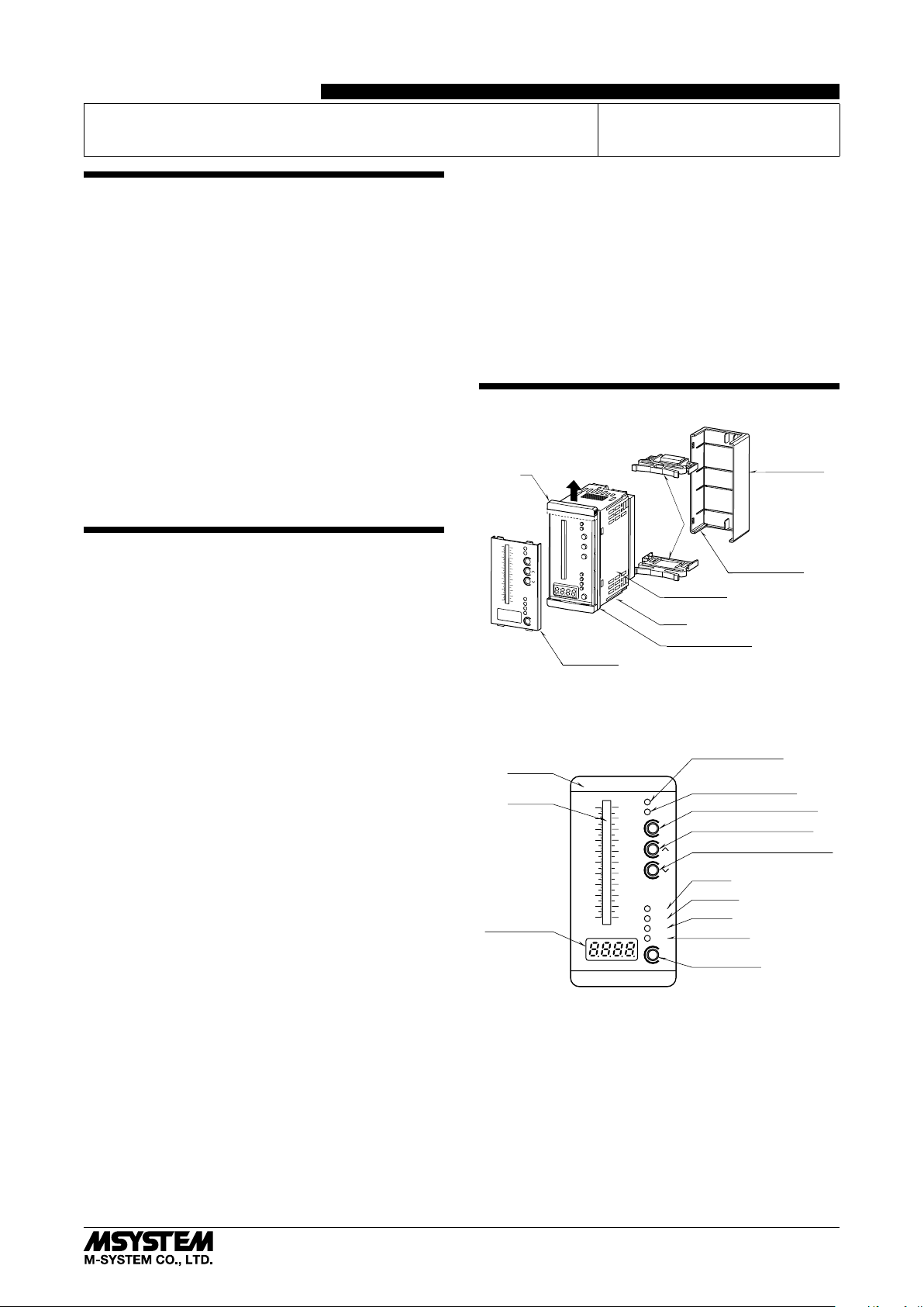
COMPONENT IDENTIFICATION
Connection
Diagram
A
Mounting
Brackets
PV
50
100
CAS
MAN
90
40
80
OUT
70
30
60
50
20
40
30
10
20
10
PV
0
0
CAS
m
%
MV
MODE
IND
%
Specifications
Body
Watertight Packing
Scale Plate
Pull up the part ‘A’ when replacing the scale plate.
■ FRONT PANEL CONFIGURATION
Tag Plate
Bargraph
Digital Display
PV
50
40
30
20
10
0
CAS
100
MAN
90
OUT
80
70
60
50
40
30
20
10
PV
0
CAS
MV
%m
MODE
IND
%
CAS Output LED
(ON at CAS Mode)
MAN Output LED
(ON at Manual Mode)
CAS-MAN Selector (OUT)
MAN Control Button (UP)
MAN Control Button (DOWN)
PV LED
CAS LED
MV LED
MODE LED
Digital Display
Selector (IND)
(behind)
Terminal Cover
■ REQUIREMENTS TO ENSURE IP65
• Observe the designated panel cutout size (45 × 92 mm).
• Single mounting only. IP65 is not ensured when the units
are clustered side by side.
• The watertight packing included in the product package
must be placed behind the front cover.
• Both mounting brackets must be fastened tightly until
they hit the panel.
• Confirm visually that the packing is not contorted or excessively run off the edge after installation.
5-2-55, Minamitsumori, Nishinari-ku, Osaka 557-0063 JAPAN
Phone: +81(6)6659-8201 Fax: +81(6)6659-8510 E-mail: info@m-system.co.jp
EM-2614 Rev.8 P. 1 / 6
Page 2
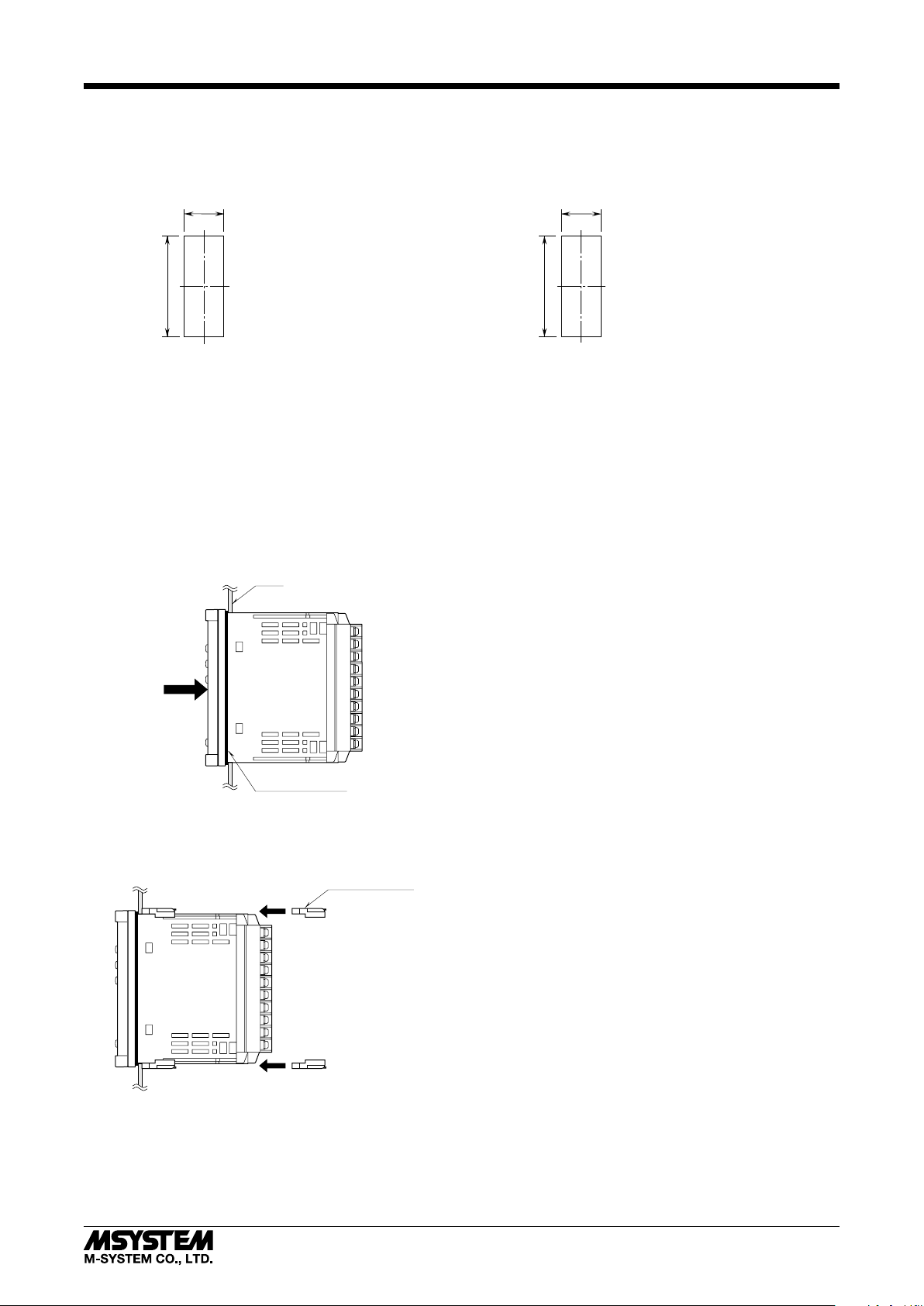
INSTALLATION
■ PANEL CUTOUT unit: mm
ABF3
• Single Mounting
(Conform to degree of protection IP65)
+ 0.6
– 0
45
+ 0.8
– 0
92
Panel thickness: 1.6 – 8.0 mm
Observe at the minimum of 3 cm above and below the units for heat dissipation.
■ HOW TO MOUNT THE UNIT ON A PANEL
1) Insert the unit into the panel cutout. The watertight
packing must be in place to hold the unit. Do not remove
it.
2) The IP65 protection is effective only with single mounting, with the designated cutout size (45 × 92 mm).
Panel
• Clustered Mounting
(Not conform to degree of protection IP65)
L
+ 0.8
– 0
92
Panel thickness: 1.6 – 8.0 mm
L = (45.5 + 48 × (N –1))
(N : number of units)
+1
–0
Watertight Packing
3) Push the mounting brackets into the grooves on top and
bottom of the rear module, until they hit the panel’s rear
side.
Mounting Bracket
5-2-55, Minamitsumori, Nishinari-ku, Osaka 557-0063 JAPAN
Phone: +81(6)6659-8201 Fax: +81(6)6659-8510 E-mail: info@m-system.co.jp
EM-2614 Rev.8 P. 2 / 6
Page 3

TERMINAL CONNECTIONS
Connect the unit as in the diagram in the following page or refer to the connection diagram on the terminal cover.
■ EXTERNAL DIMENSIONS unit: mm (inch)
ABF3
PV
50
100
90
80
40
70
60
30
50
40
20
30
20
96 (3.78)
103 (4.06)
10
10
0
0
%m
%
48 (1.89) 45 (1.77)
■ CONNECTION DIAGRAM
+
CAS INPUT
PV INPUT
1
–
2
+
5
–
6
CAS
MAN
PV
CAS
MV
MODE
MOUNTING BRACKETWATERTIGHT PACKING
TERMINAL BLOCK COVER
4–M3 SCREW
20–M3 SCREW TERMINAL
111
OUT
IND
212
313
414
515
616
717
818
919
10 20
91.5 (3.60)
2 (.08)
12.5
(.49)
+
11
–
12
15
CONTACT OUTPUT
16
MV OUTPUT
MAN STATUS
86 (3.39)
98.5 (3.88)
• When mounting, no extra space is needed between units.
REMOTE
OUTPUT SWITCHING
COMMAND
9
10
19
20
U(+)
POWER
V(–)
■ TERMINAL BLOCK
• How to remove the terminal cover
Insert the minus tip of a screwdriver into each hole at the
four corners of the cover and pull it to the direction as indicated below to separate the terminal cover.
Terminal Cover
• How to remove the terminal block
The terminal block is separable in two pieces. Loosen two
screws on top and bottom of the terminal block to separate.
Be sure to turn off the power supply, input signal and power
supply to the output relays before separating the terminal
block.
Terminal Block Screw
Terminal Block
Separable
5-2-55, Minamitsumori, Nishinari-ku, Osaka 557-0063 JAPAN
Phone: +81(6)6659-8201 Fax: +81(6)6659-8510 E-mail: info@m-system.co.jp
EM-2614 Rev.8 P. 3 / 6
Page 4

SETTING/CANCELING MANUAL OUTPUT
■ SETTING MANUAL OUTPUT (CAS to MAN mode) *
• Using CAS-MAN Selector (OUT)
1) Hold down OUT button until MAN (red) and MV (red)LED turn on (MAN mode).
2) Press ▲▼ buttons until the digital display shows a desired value.
1
ABF3
MAN
Output
LED ON
MV
(red)
MAN Control Buttons
Increase / Decrease
CAS-MAN Selector
Using CAS-MAN Selector
•
Switching by remote command (contact)
OUT
Keep
pressing
1) Short across the terminals 9 – 10. The MAN (red) and MV (red) LED turn on (MAN mode).
2) Press ▲▼ buttons until the digital display shows a desired value.
Terminal Block
Switching by remote
command (contact)
9 – 10
Closed
■ CANCELING MANUAL OUTPUT (MAN to CAS mode) *
• If you have set MAN mode by using CAS-MAN Selector (OUT)
1) Hold down OUT button until CAS (red) and PV *
CAS-MAN Selector
MAN Mode set by
using CAS-MAN Selector
If you have set MAN mode by remote command (contact)
•
OUT
3
(red) LED turn on (CAS mode).
Keep
pressing
1) Open across the terminals 9 – 10. The CAS (red) and PV*
LED ON
MAN
Output
1, *2
CAS
Output
3
MV
(red)
LED ON
3
PV*
(red)
(red) LED turn on (CAS mode).
MAN Control Buttons
Increase / Decrease
SET
SET
SET
CAS
Output
LED ON
PV*
(red)
3
SET
Terminal Block
MAN Mode set by
remote command (contact)
*1. OUT Switch cannot be controlled when PV, CAS, MV or MODE LED shows green.
*2. Setting and canceling MAN Mode may be executed using the different method.
For example, if you have set MAN Mode by using OUT Switch, you cannot cancel it by the remote command.
*3. The LED light returns to the state prior to the moment of switching from CAS to MAN when the MAN mode is canceled.
9 – 10
Open
SWITCHING DIGITAL DISPLAY
The unit switches between digital display contents and setting items when every time pressing Digital Display Selector (IND).
■ SWITCHING DIGITAL DISPLAY CONTENTS (red LED)/SETTING ITEMS (green LED)
CAS
(red)
MV
(green)
LED ON
MV
(red)
CAS
(green)
MODE
(red)
PV
(green)
Display Selector
IND
PV
(red)
MODE
(green)
Switching digital display contents (red LED) Switching setting items (green LED)
PV (red): PV input (%) PV (green): Manual operation ramp rate
CAS (red): CAS input (%) CAS (green): Retroactive time period
MV (red): MV output (%) MV (green): Transition ramp rate
MODE (red): Showing firmware version MODE (green): Not in use
5-2-55, Minamitsumori, Nishinari-ku, Osaka 557-0063 JAPAN
Phone: +81(6)6659-8201 Fax: +81(6)6659-8510 E-mail: info@m-system.co.jp
EM-2614 Rev.8 P. 4 / 6
Page 5

OTHER SETTINGS AND CHECKING FIRMWARE VERSION
ABF3
■ MANUAL OPERATION RAMP RATE*1,*
2
Setting response time required for the output goes from 0% to 100% with ▲▼ buttons in MAN mode. Selectable from 1 to 30
seconds in 1 sec. increments. (Factory set to 15 sec.)
1) Press IND button until the green LED turns on the PV LED.
2) Press ▲▼ buttons until the digital display shows a desired value.
LED ON
PV
(green)
MAN Control Buttons
SET
Increase / Decrease
Manual operation ramp rate
■ RETROACTIVE TIME PERIOD*
Digital Display Selector
IND
1
The ABF3 continuously stores the MV output during CAS control. When the loop has been turned to MAN control (contact
closure at the terminals 9 – 10), it goes back by the preset time period and holds the output. For example, with the value set
to 10 seconds, the ABF3 outputs the MV value 10 seconds before the contact has been closed.
Selectable from 0 to 30 seconds in 1 sec. increments. (Factory set to 0 sec.)
1) Press IND button until the green LED turns on the CAS LED.
2) Press ▲▼ buttons until the digital display shows a desired value.
LED ON
CAS
(green)
MAN Control Buttons
SET
Increase / Decrease
Retroactive time period
at switching CAS to MAN
Digital Display Selector
IND
■ TRANSITION RAMP RATE
If the CAS control value at the moment of switching from MAN to CAS mode is greatly deviated from the MV output value in
MAN control, the ABF3 adjusts the difference gradually in the preset ramp rate. Receiving MAN command during transition
ramp period, the ABF3 turns to MAN mode after transition ramp function is completed.
The ramp rate is set as time required for the output goes from 0% to 100%.
Selectable from 0 to 30 seconds in 1 sec. increments. (Factory set to 1 sec.)
1) Press IND button until the green LED turns on the MV LED.
2) Press ▲▼ buttons until the digital display shows a desired value.
LED ON
MV
(green)
MAN Control Buttons
SET
Increase / Decrease
Transition ramp rate
at switching MAN to CAS
Digital Display Selector
IND
■ CHECKING THE VERSION INFORMATION
To confirm the version information of the unit, press Digital Display Selector (IND) to turn ON the MODE LED (red).
*1. OUT Switch cannot be controlled when PV, CAS, MV or MODE LED shows green.
*2. Add 0.3 seconds for the total time required to go from 0% to 100%.
5-2-55, Minamitsumori, Nishinari-ku, Osaka 557-0063 JAPAN
Phone: +81(6)6659-8201 Fax: +81(6)6659-8510 E-mail: info@m-system.co.jp
EM-2614 Rev.8 P. 5 / 6
Page 6

CHECKING
1) Terminal wiring: Check that all cables are correctly connected according to the connection diagram.
2) Power input voltage: Check voltage across the terminal
19 – 20 with a multimeter.
3) Input: Check that the input signal is within 0 – 100% of
the full-scale.
4) Output: Check that the load resistance meets the described specifications.
WIRING INSTRUCTIONS
■ TIGHTENING TORQUE
Separable screw terminal wiring screw: 0.6 N·m
Separable screw terminal fixing screw: 0.6 N·m
■ SOLDERLESS TERMINAL
Refer to the drawing below for recommended ring tongue
terminal size. Spade tongue type is also applicable.
Applicable wire size: 0.25 to 0.75 mm
Recommended manufacturer: Japan Solderless Terminal
MFG. Co., Ltd., Nichifu Co., Ltd.
3.3 (.13) max
2
ABF3
6 (.24) max
mm (inch)
LIGHTNING SURGE PROTECTION
M-System offers a series of lightning surge protector for
protection against induced lightning surges. Please contact
M-System to choose appropriate models.
5-2-55, Minamitsumori, Nishinari-ku, Osaka 557-0063 JAPAN
Phone: +81(6)6659-8201 Fax: +81(6)6659-8510 E-mail: info@m-system.co.jp
EM-2614 Rev.8 P. 6 / 6
 Loading...