

Page 1

75ET
EM-7354-0003A Rev.1P. 1 / 4
BEFORE USE ....
Thank you for choosing M-System. Before use, check the
package you received as below.
If you have any problems or questions with the product,
please contact M-System's Sales Office or representatives.
This product is for use in general industrial environments,
therefore may not be suitable for applications which require
higher level of safety (e.g. safety or accident prevention
systems) or of reliability (e.g. vehicle control or combustion
control systems).
For safety, installation and maintenance of this product must
be conducted by qualified personnel.
■ PACKAGE INCLUDES:
Touch Panel Paperless Recorder................................ (1)
Installation fastener ................................................... (4)
CD-ROM (software and users manual) ..................... (1)
■ MODEL NO.
Check that model No. described on specification label is
exactly what you ordered.
■ INSTRUCTION MANUAL
This manual describes necessary points of caution when you
use this product, including installation, connection and basic
maintenance procedures. For more details, refer to the users
manual included in the CD-ROM.
POINTS OF CAUTION
This product is not designed for use in classified locations.
DO NOT use this product in explosive atmosphere.
■ POWER INPUT
• Power input rating & operational range: Check the power
rating for the unit on the specification label.
Rating 24V DC: 24V ±20%, max. 50W
• Supplying any level of power other than specified above can
damage the 75ET or the power source.
• The power cables and the signal I/O cables for the 75ET
must be located separately.
• The main circuit cables (high voltage and high current), the
signal I/O cables, and the power cables should not be bundled
together or placed near each other.
• To increase noise resistance of the power input wires, twist
the strands before connecting.
■ SAFETY PRECAUTION
• Before you remove the module, turn off the power supply
and input signal for safety.
• Do not use the 75ET in an environment where flammable
gases are present. This may result in an explosion.
• Do not disassemble or modify the 75ET in any way. Doing
so may result in a fire or an electrical shock.
• Do not strike the panel of the 75ET with a hard, heavy or
pointed object, or press the panel with excessive force. Doing
so may result in panel damage or injury.
• Do not block the 75ET's ventilation openings or use it in
areas where heat accumulates. Additionally, do not store or
use it under high-temperature conditions.
• Do not store or use the 75ET in locations subject to direct
sunlight, or where excessive dust or dirt is present.
• The 75ET is a precision instrument. Do not store or use it
where large shocks or excessive vibration can occur.
• Do not store or use the 75ET in environments subject to
chemical evaporation (such as that of organic solvents), or
where there are chemicals and/or acids present in the air.
• Do not use paint thinner or organic solvents to clean the
75ET.
• Do not turn off the power supply to the 75ET during
recording. The CF Card may be destroyed.
■ ENVIRONMENT
• Indoor use
• Standard installation for the 75ET is in a vertical panel. If
the 75ET is to be installed in a slanted panel, the panel should
not incline more than 30 degrees from the vertical.
• Environmental temperature must be within 0 to 50°C (32
to 122°F) with relative humidity within 30 to 85% RH in order
to ensure adequate life span and operation.
■ LCD PANEL
• The LCD panel’s liquid contains an irritant. If the panel is
damaged and the liquid contacts your skin, rinse immediately the contact area with running water for at least 15
minutes. If the liquid gets in your eyes, rinse immediately
your eyes with running water for at least 15 minutes and
consult a doctor.
• The following phenomena are LCD characteristics, and
NOT a product defect:
- LCD screen may show uneven brightness depending
upon displayed images or contrast settings.
- The LCD screen pixels may contain minute blank-andwhite-colored spots.
- The color displayed on the LCD screen may appear
different when seen from outside the specified viewing
angle.
- When the same image is displayed on the screen for a
long time period, an afterimage may appear when the
image is changed. If this happens, turn off the 75ET and
wait 10 seconds before restarting it.
• To prevent an afterimage:
- Set the screensaver when you plan to display the same
image for a long time period.
- Plan to change the screen image periodically so that the
same image does not remain for the long time period.
INSTRUCTION MANUAL
MODEL
75ET
PAPERLESS RECORDER
(12.1-inch touch panel)
Page 2

75ET
EM-7354-0003A Rev.1P. 2 / 4
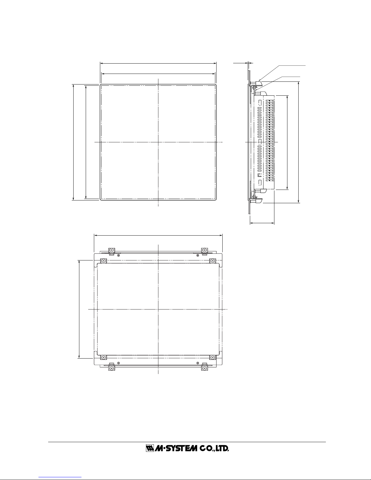
INSTALLATION
Use the mounting attachments included in the product package. Refer to the panel cutout dimensions as shown below. For use
with Panel Mount Adaptor (model: A-75), refer to the instruction manual for the model.
The A-75 panel cutout conforms to DIN 43700.
For each maintenance, operation and sufficient ventilation, at the minimum of 100 mm must be observed between the 75ET unit
and adjacent structures or equipment.
■ 75ET PANEL CUTOUT mm ■ A-75 ADAPTOR PANEL CUTOUT mm
EXTERNAL DIMENSIONS mm (inch)
■ 75ET
281
281
+2
0
+2
0
Panel thickness: 1.6 – 6.0 mm
Panel thickness: 1.6 – 10.0 mm
227.5
+1
0
4–R3 max.
301.5
+1
0
317 (12.48)
246 (9.59) (screen area)
243 (9.57)
184.5 (7.26) (screen area)
227 (8.94)
50 (1.97)8 (.31)
Page 3
75ET
EM-7354-0003A Rev.1P. 3 / 4
■ A-75 PANEL MOUNT ADAPTOR
288 (11.34)
317 (12.48) (75ET)
■ REAR VIEW
■ FRONT VIEW ■ SIDE VIEW
281 (11.06) (panel cutout)
288 (11.34)
281 (11.06) (panel cutout)
227 (8.94) (75ET)
305 (12.01)
2 (.08)
243 (9.57) (75ET)
INSTALLATION
FASTENER
ADAPTOR
PLATE B
(rear side)
61 (2.40)
Page 4

75ET
EM-7354-0003A Rev.1P. 4 / 4
TERMINAL CONNECTIONS
Connect the module as in the diagram below.
■ CONNECTION DIAGRAM ■ RS-232C INTERFACE
1
5
6
9
ABBR.
PIN NO. EXPLANATION OF FUNCTION
1 Not Used.
BB (RD) 2 Received Data
BA (SD) 3 Transmitted Data
CD (ER) 4 DTE Ready
AB (SG) 5 Signal Common
CF (CD) 6 Received Line Signal Detector
CA (RS) 7 Request to Send
CB (CS) 8 Clear to Send
9 Do Not Connect.
M-SYSTEM WARRANTY
M-System warrants such new M-System product which it manufactures to be free from defects in materials and workmanship during the 36-month period following the date that such
product was originally purchased if such product has been used under normal operating conditions and properly maintained, M-System's sole liability, and purchaser's exclusive remedies,
under this warranty are, at M-System's option, the repair, replacement or refund of the purchase price of any M-System product which is defective under the terms of this warranty. To
submit a claim under this warranty, the purchaser must return, at its expense, the defective M-System product to the below address together with a copy of its original sales invoice.
THIS IS THE ONLY WARRANTY APPLICABLE TO M-SYSTEM PRODUCT AND IS IN LIEU OF ALL OTHER WARRANTIES, EXPRESS OR IMPLIED, INCLUDING ANY IMPLIED
WARRANTIES OF MERCHANTABILITY OR FITNESS FOR A PARTICULAR PURPOSE. M-SYSTEM SHALL HAVE NO LIABILITY FOR CONSEQUENTIAL, INCIDENTAL OR
SPECIAL DAMAGES OF ANY KIND WHATSOEVER.
M-System Co., Ltd., 5-2-55, Minamitsumori, Nishinari-ku, Osaka 557-0063 JAPAN, Phone: (06) 6659-8201, Fax: (06) 6659-8510, E-mail: info@m-system.co.jp
CF CARD SLOT
MODULAR JACK
D-SUB CONNECTOR
10BASE-T
RS-232C
+
–
FG
POWER
GROUND
Page 5

1
7xETBLD USERS MANUAL EM-7353-0003C
PAPERLESS RECORDING SYSTEM 7xET SERIES
PC CONFIGURATOR
Model: 7xETBLD
Users Manual
Page 6

2
7xETBLD USERS MANUAL EM-7353-0003C
Contents
1. GENERAL DESCRIPTIONS ........................................................................ 3
1.1 7xETBLD FEATURES ................................................................................................................. 3
1.2 SYSTEM REQUIREMENTS ........................................................................................................ 3
1.3 PROGRAMMING FUNCTIONS ................................................................................................... 3
2STARTING & USING THE 7xETBLD .......................................................... 4
2.1 CONNECTING THE 7xET ........................................................................................................... 4
2.2 INSTALLING / UNINSTALLING THE 7xETBLD........................................................................... 4
2.2.1 INSTALL........................................................................................................................... 4
2.2.2 UNINSTALL...................................................................................................................... 4
2.3 STARTING / STOPPING THE 7xETBLD..................................................................................... 5
2.4 SETTING ON THE 7xETBLD ...................................................................................................... 6
2.4.1 COMMUNICATION SETTING.......................................................................................... 6
2.4.2 STORING RATE ...............................................................................................................6
2.4.3 DATA STORING METHOD............................................................................................... 6
2.4.4 START MODE .................................................................................................................. 6
2.4.5 TEMPERATURE UNIT..................................................................................................... 6
2.4.6 DATA STORING FORM.................................................................................................... 7
2.4.7 DIGITAL DISPLAY METHOD ........................................................................................... 7
2.4.8 DISPLAY RATE ................................................................................................................ 7
2.4.9 CHART SPEED................................................................................................................7
2.4.10 DIGITAL DISPLAY............................................................................................................ 7
2.4.11 GRAPH............................................................................................................................. 7
2.4.12 DATA FILE USED VOLUME............................................................................................. 7
2.4.13 SCREEN SAVER ............................................................................................................. 7
2.4.14 NODE SETTING ..............................................................................................................7
2.4.15 PEN SETTING ................................................................................................................. 8
2.4.16 PEN SELECT ................................................................................................................. 12
2.5 FILE OPERATION BUTTONS ................................................................................................... 13
2.5.1 FILE READ..................................................................................................................... 13
2.5.2 FILE WRITE ................................................................................................................... 13
2.5.3 SETTING TO CSV.......................................................................................................... 13
2.5.4 CF DATA CREATE ......................................................................................................... 13
2.5.5 CF DATA TO CSV .......................................................................................................... 14
2.5.6 CF DATA TO MRD.......................................................................................................... 15
2.5.7 DATA VERSION CONVERT........................................................................................... 15
2.6 ONLINE OPERATION BUTTONS ............................................................................................. 16
2.6.1 UPLOAD......................................................................................................................... 16
2.6.2 DOWNLOAD (All)........................................................................................................... 16
2.6.3 DOWNLOAD (Runtime) ................................................................................................. 16
2.6.4 REMOTE START / STOP ............................................................................................... 16
2.6.5 PULSE COUNT PRESET .............................................................................................. 17
2.6.6 REMOTE CSV TOOL..................................................................................................... 17
2.6.7 REMOTE MRD TOOL .................................................................................................... 18
APPENDIX-A ETHERNET CABLE ................................................................................................... 18
Page 7

3
7xETBLD USERS MANUAL EM-7353-0003C
1. GENERAL DESCRIPTIONS
Thank you for choosing M-System’s Paperless Recording System.
The Model 7xETBLD is an easy PC Configuration T ool Software which enables the user to configure the 7xET Series
Touch Panel Paperless Recorders (models: 73ET, 74ET and 75ET) remotely via Ethernet.
This users manual describes PC requirements for the software and its use. For detailed information about the
functions of the 7xET Series, please refer to its respective manual.
Descriptions in this manual is applicable to the 7xETBLD Ver. 3.00x.
1.1 7xETBLD FEATURES
The 7xETBLD enables the user to set parameters to a 7xET remotely via Ethernet simply by specifying its IP
address. It can also upload preset 7xET configuration remotely.
Specific set of configurations can be saved on the PC and then reloaded on the program later when necessary.
The 7xET’s recording operations can be started/stopped by commands from the 7xETBLD program.
1.2 SYSTEM REQUIREMENTS
PC: IBM PC/AT compatible
OS: Window 2000 or XP
Screen area: 1024 x 768 pixels
Display color: 65000 colors (16-bit high color)
Ethernet media: 10BASE-T (73ET is compatible with 100BASE-TX)
1.3 PROGRAMMING FUNCTIONS
Parameters: Communication setting, Storing rate, Data storing method, Start mode,
Temperature unit, Data storing form, Digital display type, Display rate,
Chart speed, Digital display (auto hide), Graph (chart direction),
Data file used volume, Screen saver,
Node setting, Pen setting (common, analog, discrete, alarm)
Pulse count preset: Preset individual pens
Preset all pens
Communication: Download (configuration to the 7xET)
Upload (configuration from the 7xET)
File read / write
Remote start / stop
CF Data create: Creating 7xET.7xDA and 7xET.7xCA files on the CF Card.
CF Data to CSV: Converting data at the specific time period stored in the CF Card into a CSV file.
Getting the time-specific data via Ethernet and converting it into a CSV file.
CF Data to MRD: Converting data at the specific time period stored in the CF Card into a MRD file
which is readable on the MSR128 (file name: yymmdd.MRD).
Getting the time-specific data via Ethernet and converting it into a MRD file.
Data Version Convert: Converting old-version files into the latest-version ones.
Setting to CSV: Saving the 7xETBLD parameters in CSV format.
Page 8

4
7xETBLD USERS MANUAL EM-7353-0003C
2STARTING & USING THE 7xETBLD
2.1 CONNECTING THE 7xET
Confirm that the PC on which the 7xETBLD is used is connected to the 7xET via Ethernet. The 7xET’s IP address
must be properly set in advance. Please refer to the 7xET users manual for detailed information about IP address
setting.
The 7xETBLD Ver. 3.00x is applicable to the following versions of the 7xET Series.
73ET: Ver. 6.00x
74ET: Ver. 3.00x
75ET: Ver. 3.00x
2.2 INSTALLING / UNINSTALLING THE 7xETBLD
If you already have the 7xETBLD program installed in your PC, remove it following the procedure explained in 2.2.2
before installing a new one.
2.2.1 INSTALL
1. Insert the Paperless Recorder Software Package CD (model: CHARTLSP2) into the CD-ROM drive on your PC.
The 7xETBLD Install Program automatically starts up. If the program does not start up automatically, open
Control Panel and choose Add/Remove Programs.
2. Locate the setup program under the 7xETBLD folder in the CD
3. Start Setup.exe. and follow instructions on the screen.
4. With the installation complete, ‘7xETBLD’ menu is created in ‘Programs’ menu.
2.2.2 UNINSTALL
1. Press Start on the task bar and choose Control Panel from Settings menu. (Double-click My Computer icon on
the desktop and choose Control Panel.)
2. Double-click Add/Remove Programs and follow instructions on the screen.
Page 9
5
7xETBLD USERS MANUAL EM-7353-0003C
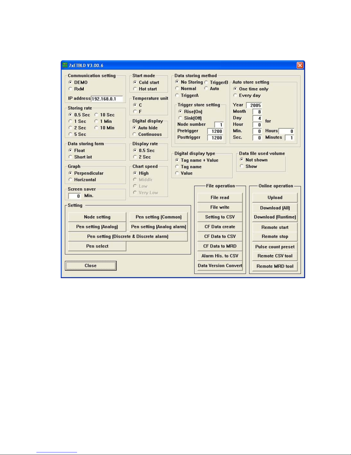
2.3 STARTING / STOPPING THE 7xETBLD
Press Start on the task bar, choose Programs and locate 7xETBLD. Start 7xETBLD.exe and the 7xET PC Configurator
window appears on the screen as shown in Figure 1. Alternately, double-click 7xETBLD.exe shortcut icon on the
desktop to start the program.
Figure 1: 7xET PC Configurator window.
In order to quit the window, click [Close] button at the right-bottom.
Page 10

6
7xETBLD USERS MANUAL EM-7353-0003C
2.4 SETTING ON THE 7xETBLD
2.4.1 COMMUNICATION SETTING
DEMO: Y ou can run the 7xET program without actual signal input for learning, evaluation and demonstra-
tion when you choose DEMO.
RxM: Choose this option when you connect R1M/R2M via Modbus RTU.
IP address: Enter 7xET’s static IP address. 192.168.0.1 entered in the field upon the first startup is M-Sys-
tem’s ex-factory setting.
2.4.2 STORING RATE
Choose among 0.5 sec., 1 sec., 2 sec., 5 sec., 10 sec., 1 min., and 10 min.
2.4.3 DATA STORING METHOD
There are four (4) storing modes as explained below:
No storing: Sampled data are plotted on the screen but no recording is executed.
Normal: Recording is manually initiated and stopped. Data is continuously stored while the recording is on.
Trigger (A): Remote trigger. Data is automatically recorded while the external trigger condition (input) is true.
Trigger (B): Event Recording. The 7xET detects an external event by trigger signal, and stores preset number
of samples before and after the moment of event.
Auto: Recording is automatically initiated and stopped at a predefined time.
Trigger (A), remote trigger mode setting
Remote trigger mode is applicable only to the R1M or R2M series I/O modules.
Data is automatically recorded while the external trigger condition (input) is true.
Condition: Specify whether the recorder should identify On or Off of the contact signal as trigger condi-
tion. For example, when the Condition is set to On, the 7xET stores data while the signal is On
and stops recording when it is turned to Off.
Node Number: Specify which R1M/R2M device connected to the 7xET is used to trigger. Enter numbers and
alphabets on the alphanumeric keypad which opens by pressing the current selection.
Trigger (B), event recording mode setting
Event recording mode is applicable only to the R1M or R2M series I/O modules.
Recording is automatically initiated according to predetermined trigger conditions and preset number of samples
before and after the moment of event are stored.
Rise or Sink: Specify whether the recorder should identify a rise or sink of the contact signal as trigger.
Node number: Specify which R1M/R2M device connected to the PC is used to trigger.
Pretrigger / Posttrigger: 1200 samples at the maximum for each can be stored. Specify numbers of samples to
be stored before (Pretrigger) and after (Posttrigger) the event respectively.
Pretrigger recording is applicable only when the storing rate is set to 0.5 or 1 sec.
Auto store setting
Either ‘One time only’ or ‘Every day’ option can be selected.
When you choose ‘One time only’ option, data is stored once at a predefined time. With ‘Every day’ option, the 7xET
runs recording once per day at a predefined time.
Specify time and duration of a recording cycle, including a date for ‘One time only’ recording. For ‘Every day’
recording, you do not need to specify ‘Year,’ ‘Month’ or ‘Day.’
2.4.4 START MODE
Cold Start: At a restart, the 7xET stands by showing the initial view.
Hot Start: At a restart, the 7xET automatically starts recording.
2.4.5 TEMPERATURE UNIT
Choose either °C (Celsius) or °F (Fahrenheit).
Page 11
7
7xETBLD USERS MANUAL EM-7353-0003C
2.4.6 DATA STORING FORM
Float (floating point): Selected when you need to store data including decimal fractions. The 4-byte-long
data is better in data precision but the total storable time in the CF Card becomes
shorter compared from Short Int.
Short int (short integer): Integer data with hypothetical fixed decimal point. The 2-byte-long data is not as pre-
cise (one decimal place) as Float type is, but the total storable time in the CF Card is
longer.
2.4.7 DIGITAL DISPLAY METHOD
Tag name + Value: The momentary value and the tag name of the data plotted on the screen.
Tag name: The tag name of the data plotted on the screen.
Value: The momentary value of the data plotted on the screen.
2.4.8 DISPLAY RATE
Choose between 0.5 sec. and 2 sec.
2.4.9 CHART SPEED
Choose among High, Middle, Low and Very Low.
When you choose 0.5 sec. for the storing rate and/or the display rate, only High speed is selectable.
2.4.10 DIGITAL DISPLAY
Specify either to show or hide the digital display on the Record view. With ‘Horizontal’ graph direction, only ‘Regular’
can be specified.
Auto Hide: Digital display is automatically hidden in 30 seconds after it appears on the screen. Click the area
of the display to call it up.
Regular: Digital display remains on the screen.
2.4.11 GRAPH
Specify the plotting direction, Perpendicular or Horizontal.
2.4.12 DATA FILE USED VOLUME
Specify either to show or hide the bargraph indicator on the Overview.
2.4.13 SCREEN SAVER
Enter a desired time in minutes to initiate the screen saver. With the time set to zero (0), the screen saver is
deactivated.
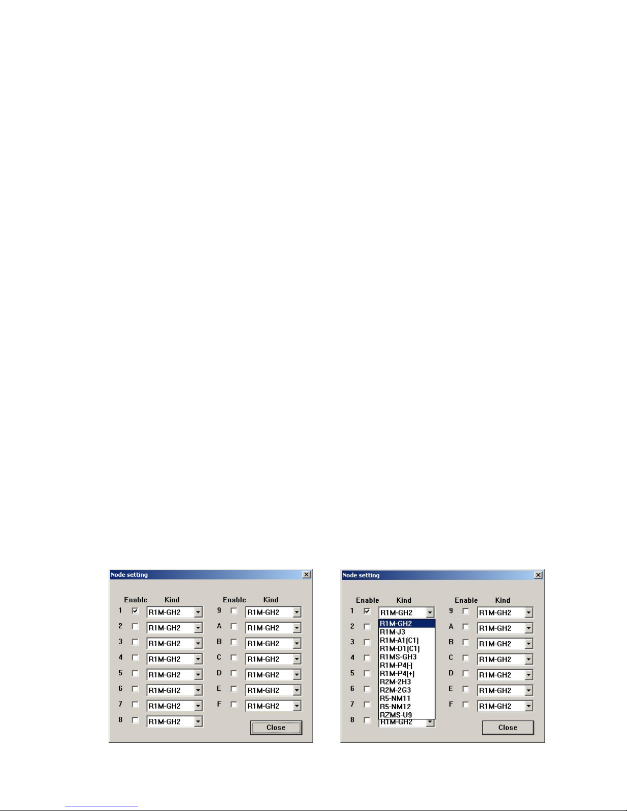
2.4.14 NODE SETTING
Pressing [Node setting] button opens the window shown in Figure 2a.
Enter ✔ mark to enable specific node numbers. Then specify I/O module type as shown in Figure 2b.
Figure 2a: Node setting (1) Figure 2b: Node setting (2)
Page 12
8
7xETBLD USERS MANUAL EM-7353-0003C
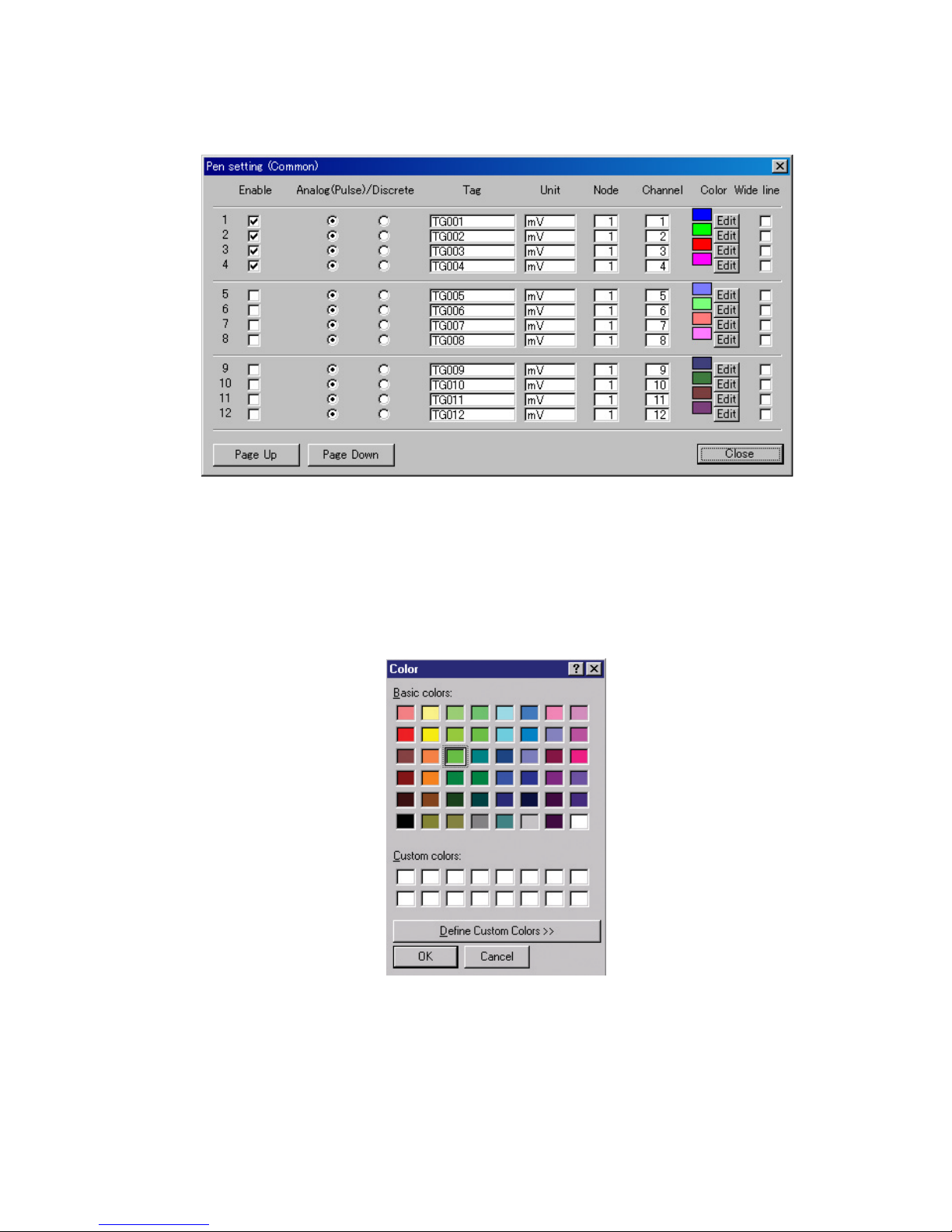
2.4.15 PEN SETTING
Pen setting (Common)
Pressing [Pen setting (Common)] button opens the window shown in Figure 3.
Figure 3: Pen setting (Common).
Enable: Enter ✔ mark to activate specific pens.
Analog (Pulse)/Discrete: Choose Analog or Discrete signal for each pen.
Tag / Unit: Enter tag names and engineering unit. Up to 8 alphanumerical characters for Tag, 4 charac-
ters for Unit.
Node / Channel: Enter node and channel numbers.
Color: Pressing [Edit] button opens the window shown in Figure 4. Select a color from the palette.
You can also compose a new color.
Figure 4: Color.
Wide Line: Enter ✔ mark to use a wide line on the screen for the pen.
Page Up / Page Down: Pressing this button shows next / previous 12 pens.
Close: Use [Close] button to quit the window. Clicking [X] button at the right-top of the window simply
resets the present setting to a default one.
Pens not selected to be ‘Enabled’ in Pen Setting (Common) are not shown in the views for Pen Setting (Analog) or
Pen Setting (Discrete & Discrete Alarm). Analog signal pens are not shown in Pen Setting (Discrete & Discrete
Alarm) view. Likewise, discrete signal pens are not shown in Pen Setting (Analog).
Page 13
9
7xETBLD USERS MANUAL EM-7353-0003C
Pen setting (Analog)
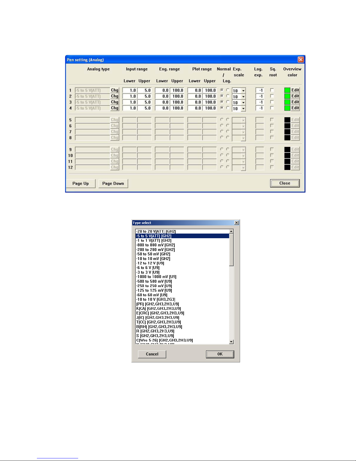
Pressing [Pen setting (Analog)] button opens the window shown in Figure 5.
Set channels to which ‘Analog’ is selected in ‘Pen setting (Common)’ window.
Figure 5: Pen setting (Analog).
Analog type: Choose an analog input type for each pen. In order to change setting, press [Chg] button
and choose a new type from the list shown in ‘Type select’ window as in Figure 6.
Figure 6: Type select.
Input range: Specify within the actual upper and lower ranges referred to as 0% and 100% respectively .
This range is the maximum range plotted on the screen. For a thermocouple/RTD input,
this setting is unavailable.
Engineering range: Specify the scaled range in actual engineering unit. The engineering range is shown on
the digital meter when actual recording is running. For a thermocouple/RTD input, this
setting is unavailable.
Plot range: Values in engineering unit for the plot range displayed on the chart. These values are
usually the same as Engineering Range values. Set a narrower range when you want to
enlarge a particular section of the Engineering Range.
Page 14
10
7xETBLD USERS MANUAL EM-7353-0003C
Normal / Log.: When Normal plotting is selected, the plot area is divided equally. When Logarithmic is
selected, the plot area is divided in specified scale of exponents of 10.
Exponential scale: Specify how many divisions you wish to have in the plot range among 10, 5, 4, 2, and 1.
Log. plot pos. exponent: Specify the lower limit of exponent within -9 to 8.
Square Root: Input data is square-root-extracted when this setting is enabled.
Overview color: Specify the analog data bargraph color used on the Overview. Press [Edit] to call up the
color palette.
Pen setting (Analog alarm)
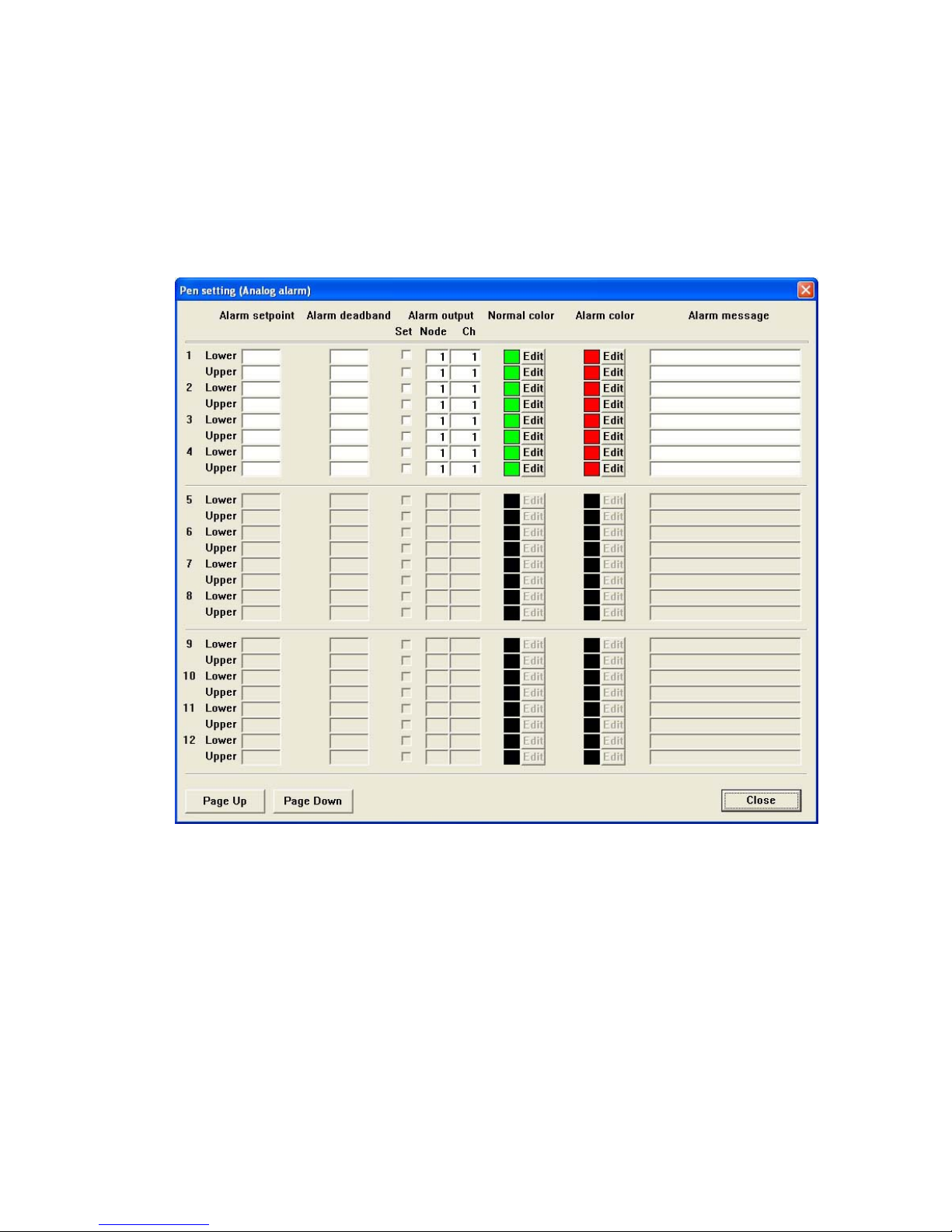
Pressing [Pen setting (Analog alarm)] button opens the window shown in Figure 7.
Figure 7: Pen setting (Analog alarm)
Alarm setpoint: Specify Lower (Low) and Upper (High) setpoints in engineering unit within the Engineering
Range. Leave the fields blank if you do not need an alarm output.
Alarm deadband: Alarms are reset when the signal goes out of the alarm zone by the deadband values
specified for each alarm setpoint. Leave the fields blank if you do not need a deadband.
Lower / Upper alarm output: Alarm contact outputs can be provided to external output devices. Enable the
function by entering ✔ mark in ‘Set’ box for the pen and specify node number and channel
number of the output module.
Normal & Alarm color: Colors specified for normal and alarm conditions are used for digital indicator values on
the Record view. Press Edit and use the color palette to specify the colors.
Alarm message: Specify the comment for the alarm trip used in the Alarm History. Max. 10 characters.
Page 15
11
7xETBLD USERS MANUAL EM-7353-0003C
Pen setting (Discrete)
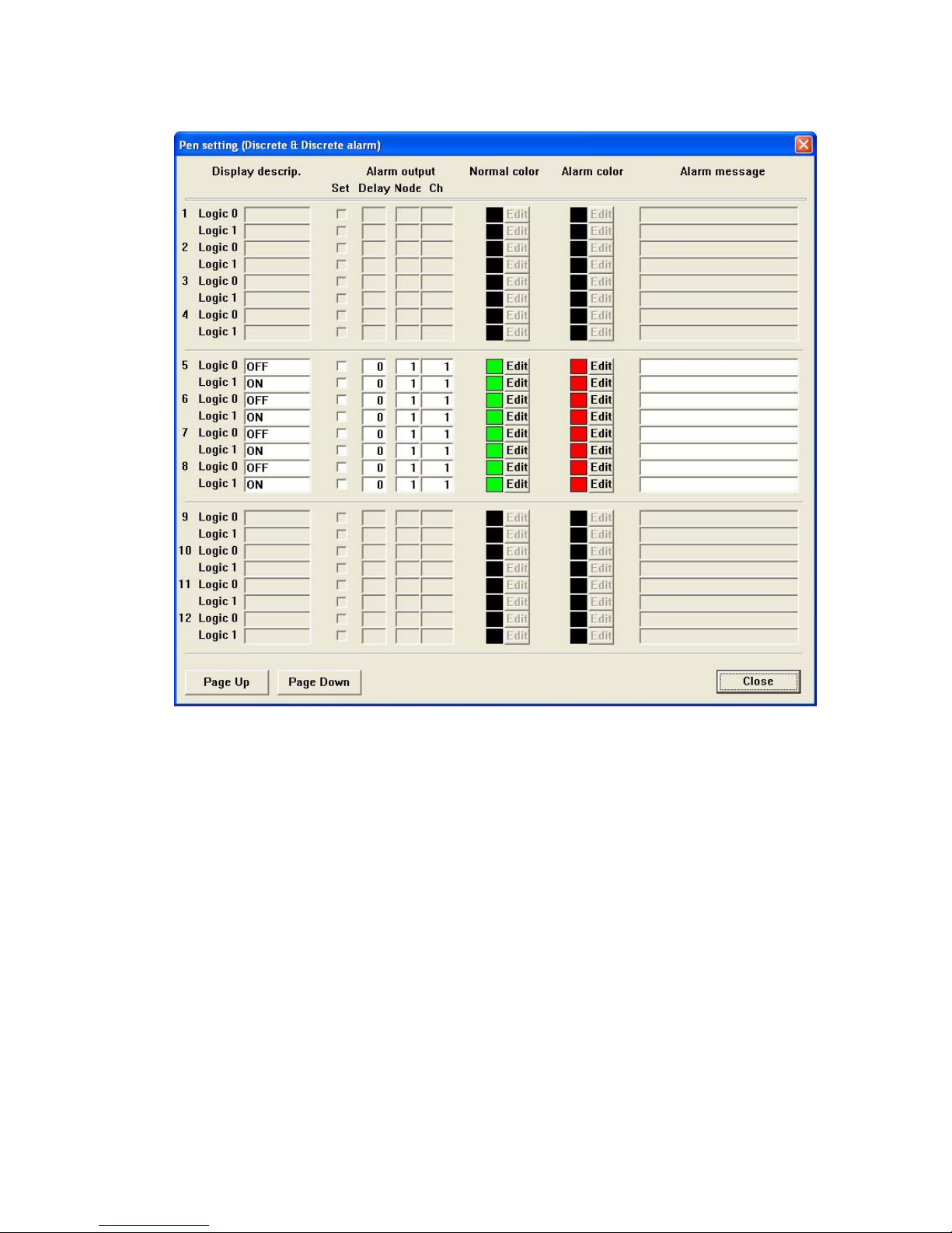
Pressing [Pen setting (Discrete)] button opens the window shown in Figure 8.
Figure 8: Pen setting (Discrete).
Display description: Specify message assigned respectively to Logic 0 and Logic 1 status with up to 5 charac-
ters. The message is shown on the digital meter instead of analog value.
Logic 0 & Logic 1 alarm output: Alarm contact outputs can be provided to external output devices. Enable the
function by entering ✔ mark in ‘Set’ box for the pen and specify node number and channel
number of the output module.
Normal & Alarm color: Colors specified for normal and alarm conditions are used for digital indicator on the
Record view. Press Edit and use the color palette to specify the colors.
Alarm message: Specify the comment for the true/false status for each Logic 0 and 1 bit used in the Alarm
History. Max. 10 characters.
Page 16
12
7xETBLD USERS MANUAL EM-7353-0003C
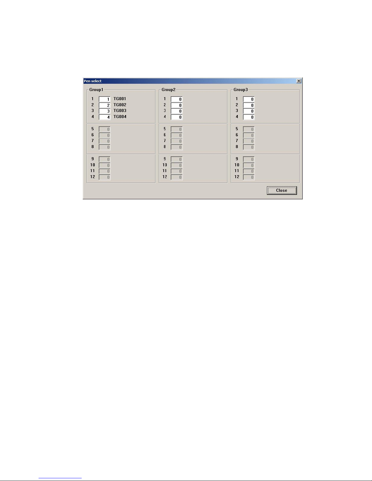
2.4.16 PEN SELECT
Pen Select is used to assign signal channels to be plotted on the screen (Figure 9).
Max. 36 pens (three groups) can be plotted on the screen except that it is limited to 12 pens when the storing rate
and/or display rate are set to 0.5 sec.
Enter the channel No. in the field and the tag name for the pen is indicated to the right. Enter 0 when you do not want
to assign any pen to the channel.
Figure 9: Pen select.
Page 17
13
7xETBLD USERS MANUAL EM-7353-0003C
2.5 FILE OPERATION BUTTONS
2.5.1 FILE READ
When you need a specific set of parameter settings, press [File read] and choose one of the parameter files saved
as in 2.5.2.
2.5.2 FILE WRITE
Parameters set on the 7xETBLD can be saved in a file with user-specified file name (up to 8 characters).
Parameter contents uploaded from the 7xET also can be saved in the same manner.
When you use a file created on the 7xETBLD for the 7xET, the file name must be 7xET.7xPA. Add .7xP A at the end
of the file name.
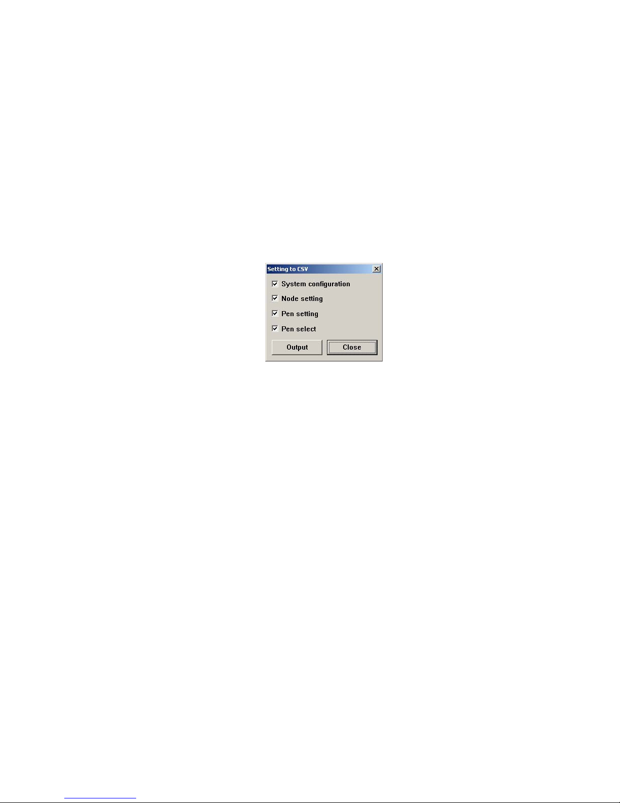
2.5.3 SETTING TO CSV
Parameters set on the 7xETBLD can be saved in the CSV format.
Parameter contents uploaded from the 7xET also can be saved in the same manner.
Pressing [Setting to CSV] opens up the window shown in Figure 10 on the screen.
Figure 10. Setting to CSV.
System configuration: Communication setting, Storing rate, Data storing method, Start mode,
Temperature unit, Data storing form, Digital display type, Display rate,
Chart speed, Digital display (auto hide), Graph (chart direction),
Data file used volume, Screen saver,
Node setting, Pen setting (common, analog, discrete, alarm)
Node setting: Node number and device
Pen configuration: Common pen setting, Analog pen setting, Analog alarm setting, Discrete pen and
alarm setting
Pen select Pen number and tag name
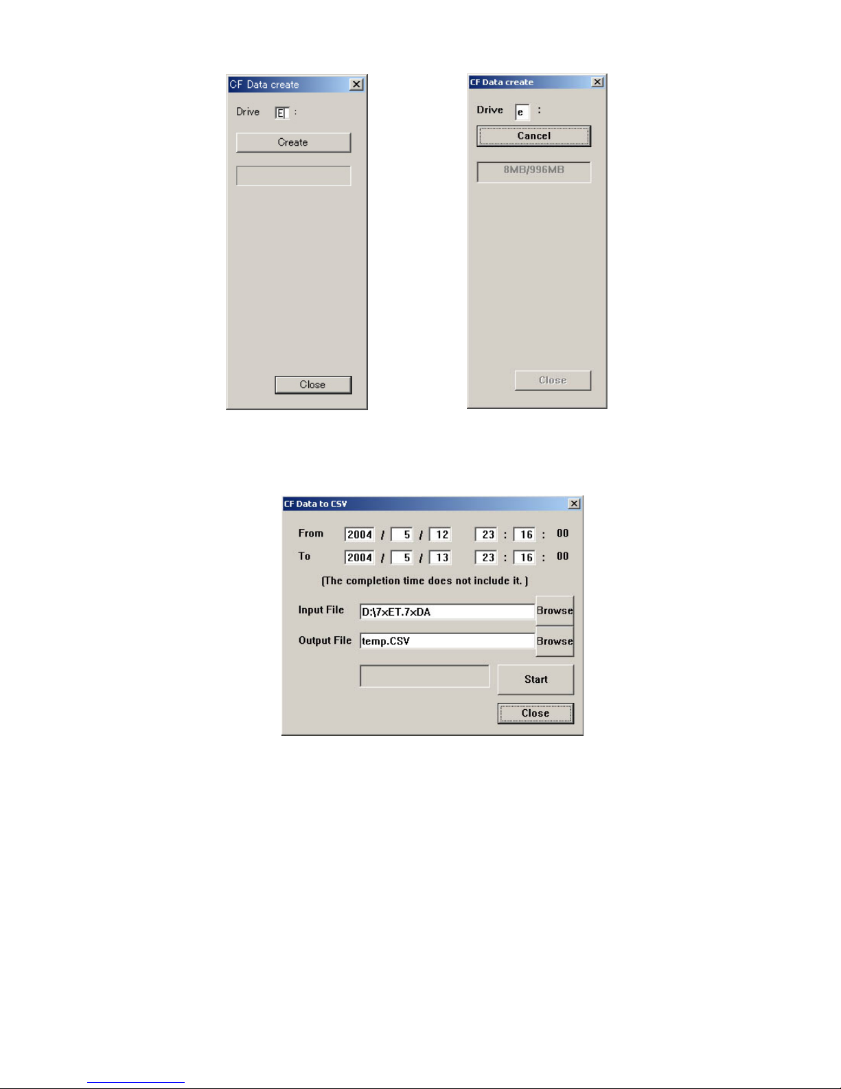
2.5.4 CF DATA CREATE
The 7xET automatically creates a data area dedicated to store data files when it starts up. It can also be created on
the PC using the 7xETBLD.
Press [CF Data create] and the window shown in Figure 11 appears on the screen.
Enter the drive ID where you have a CF Card and press [Create]. Then the window is replaced with the one shown
in Figure 12.
Pressing [Cancel] stops creating the file.
The field below the [Cancel] button shows two figures: file size to be created on the right, file size being created on
the left.
When the operation is complete, [Congratulations!] appears on the screen.
Page 18
14
7xETBLD USERS MANUAL EM-7353-0003C
Figure 11. CF Data create Figure 12. CF Data create in file creating process
2.5.5 CF DATA TO CSV
Pressing [CF Data to CSV] button opens the dialog box CF Data to CSV (Figure 13).
Figure 13: CF Data to CSV.
Insert the CF Card to a card reader.
Specify the date and time to start and stop reading. (Seconds cannot be specified.)
Specify in ‘Input File’ field the file name you want to convert.
Specify in ‘Output File’ field the directory path and the CSV file name.
Click [Start].
Remark 1: The data at the time index specified in ‘To’ field is Not included in the converted file. For example, if you
specify ‘T o 10:00:00’ with 1-minute storing rate, the data is converted up to 9:59:00. If you need the data at 10:00:00,
specify ‘To 10:01:00.’
Remark 2: Data stored in Float form are converted into values with two decimal points.
Page 19
15
7xETBLD USERS MANUAL EM-7353-0003C
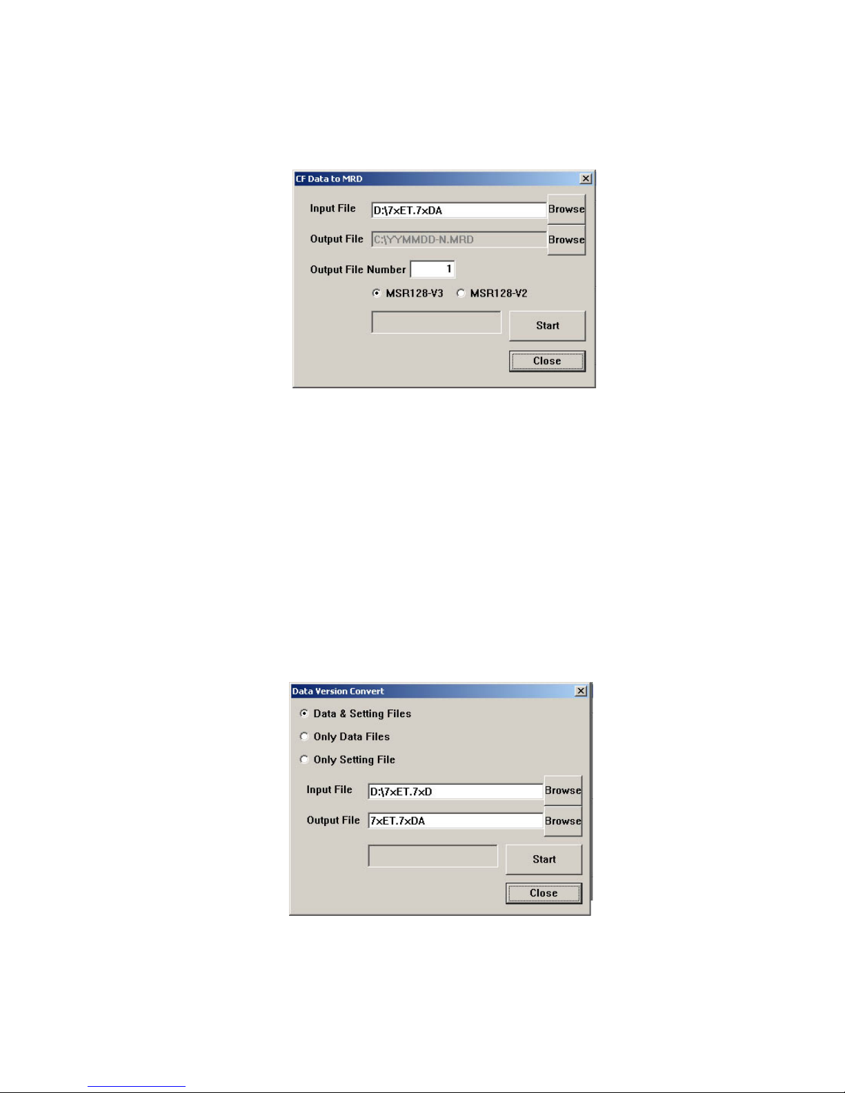
2.5.6 CF DATA TO MRD
Data stored by the 7xET can be converted into the format compatible with the MSR128-V2 or MSR128-V3 (MRD
File) so that the data can be displayed on the MSR128 software.
This procedure is not required for the MSR128-V4.
Pressing [CF Data to MRD] button opens the dialog box CF Data to MRD (Figure 14).
Figure 14: CF Data to MRD.
Insert the CF Card to a card reader.
Specify in ‘Input File’ field the 7xET file name you want to convert.
Specify in ‘Output File’ field the directory path where the converted MRD file is to be saved.
Specify in ‘Output File Number’ the number to be added at the end of the new file name (‘N’ of the file name based
on the date ‘YYMMDD-N.’) N = 1 through 9999.
Choose the target MSR128 software version.
Click [Start].
2.5.7 DATA VERSION CONVERT
The 7xET creates/uses three types of file: Data File, Setting File and Control File.
The older version files can be converted into the new version files compatible with the 7xET/0003 (73ET V er.6.00x,
74ET Ver.3.00, 75ET Ver.3.00).
73ET Ver.4.0x, 74ET Ver.1.0x, 75ET Ver.1.0x
(1) Pressing [Data Version Convert] button opens the dialog box Data Version Convert (Figure 15).
Figure 15: Data Version Convert.
Page 20

16
7xETBLD USERS MANUAL EM-7353-0003C
(2) Specify the type of files you want to convert.
Data & Setting Files: All files stored in the 7xET are converted.
Only Data Files: Data Files and Control File are converted.
Only Setting File: Only the Setting File is converted.
(3) Specify in ‘Input File’ field the 7xET file name you want to convert. If you have selected ‘Data & Setting Files’ to
be converted, specify only the data file name.
(4) Specify in ‘Output File’ field the directory path and the file name.
(5) Click [Start]. When the message “” disappears, the conversion of Data File and Control File is complete. For the
Setting File, go through the following procedure.
(6) Click [File Read] and upload the Setting File.
(7) Click [File Write] to store the file again. Now the file is compatible with the 7xET/0003.
73ET Ver.5.0x, 74ET Ver.2.0x, 75ET Ver.2.0x
There is no need of converting Data and Control files. Go through the above procedure (6) and (7) to convert the
Setting file.
2.6 ONLINE OPERATION BUTTONS
Online Operation Buttons are accessible only when the 7xET is connected to a PC installed with the 7xETBLD via
Ethernet. Before using these functions, confirm that an appropriate IP address is set to the 7xET.
2.6.1 UPLOAD
The 7xETBLD can read the current settings on the 7xET. Enter IP address of the 7xET in ‘Communication setting’
and press [Upload] button. When the upload is successfully done, ‘Congratulations!’ appears on the screen. Uploading
can be executed only while recording is stopped.
2.6.2 DOWNLOAD (All)
Pressing [Download] button downloads the current settings configured on the 7xETBLD to the 7xET. When the
download is successfully complete, ‘Congratulations!’ appears on the screen. Downloading can be executed only
while recording is stopped.
2.6.3 DOWNLOAD (Runtime)
The following parameters, runtime programmable items, can be downloaded even while recording.
Digital display pen numbers
Digital display
Graph
Screen saver
Pen color (Pen setting, common)
Wide line (Pen setting, common)
Plot range (Pen setting, analog)
Logarithmic plot position exponent (Pen setting, analog)
Pen setting (analog alarm)
Pen setting (discrete alarm)
Display pens setting
When the download is successfully complete, ‘Congratulations!’ appears on the screen.
2.6.4 REMOTE START / STOP
You can remotely start / stop the 7xET with these control buttons. When you need to change and download settings,
the 7xET can be stopped at any time.
Page 21
17
7xETBLD USERS MANUAL EM-7353-0003C
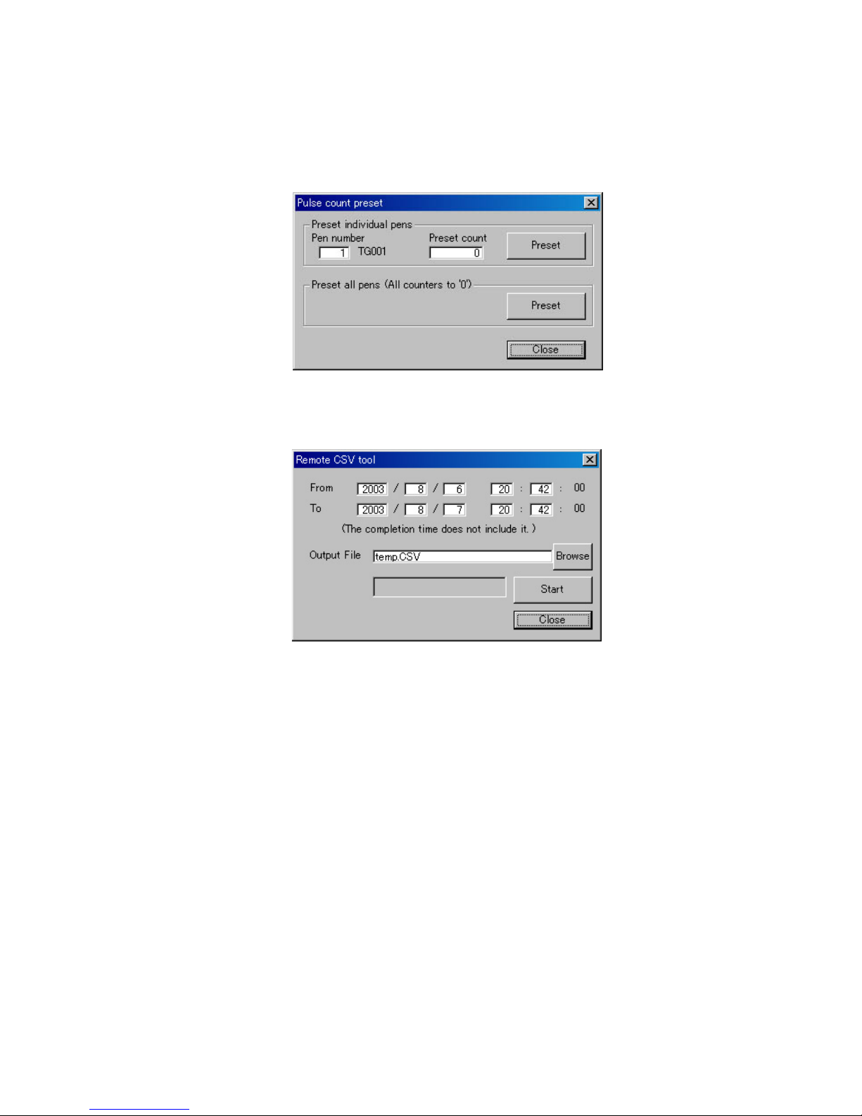
2.6.5 PULSE COUNT PRESET
The accumulated count data on the R1M-P4 can be reset to preset values on the 7xETBLD menu.
Click [Pulse Count Preset] to open the dialog box to open the Pulse Count Preset (Figure 16).
Preset individual pens: Specify the pen number and desired preset value and click Preset, and the R1M-P4
data for the specific channel are reset.
Preset all pens: Used to reset all count values to zero.
Figure 16: Pulse count preset.
2.6.6 REMOTE CSV TOOL
‘CF Data to CSV’ file conversion can be executed also via Ethernet.
Figure 17: Remote CSV Tool.
Specify the date and time to start and stop reading. (Seconds cannot be specified.)
Specify in ‘Output File’ field the directory path and the CSV file name.
Click [Start].
Remark 1: The data at the time index specified in ‘To’ field is Not included in the converted file. For example, if you
specify ‘T o 10:00:00’ with 1-minute storing rate, the data is converted up to 9:59:00. If you need the data at 10:00:00,
specify ‘To 10:01:00.’
Remark 2: Data stored in Float form are converted into values with two decimal points.
Page 22
18
7xETBLD USERS MANUAL EM-7353-0003C
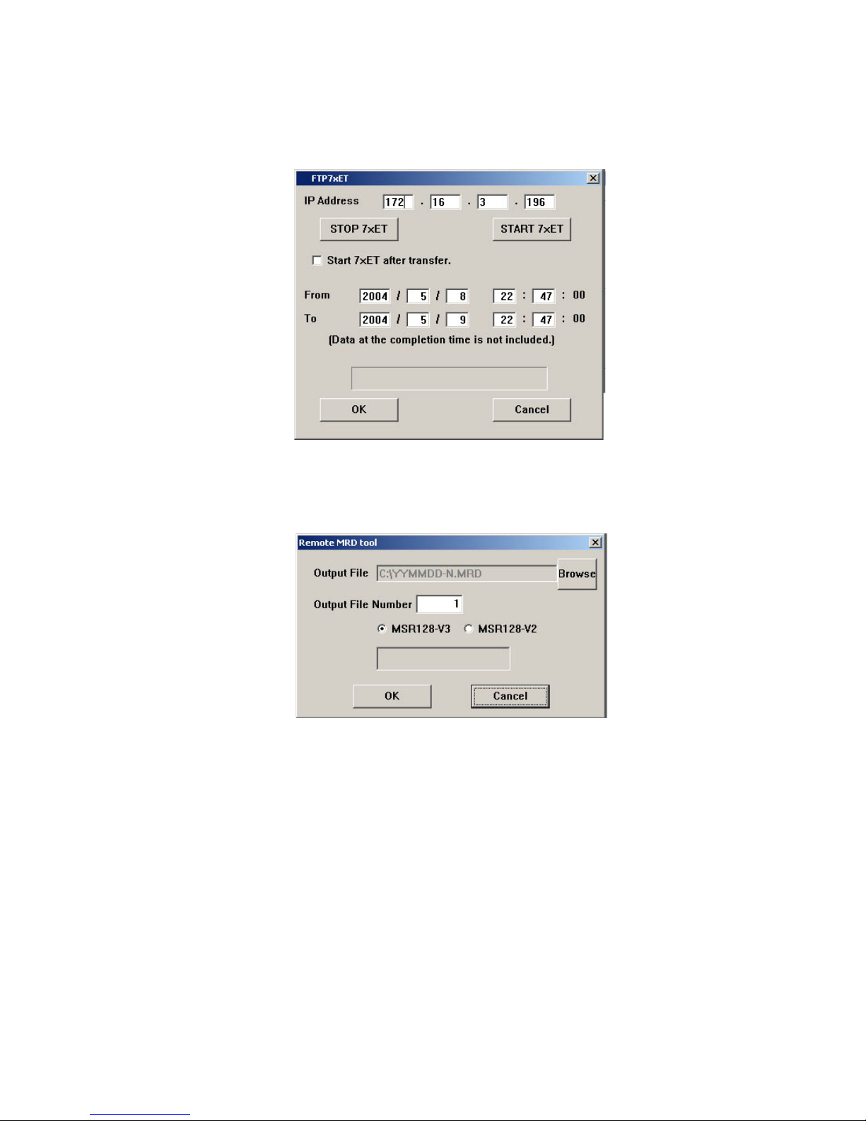
2.6.7 REMOTE MRD TOOL
‘CF Data to MRD’ file conversion can be executed also via Ethernet.
Data stored by the 7xET can be converted into the format compatible with the MSR128-V2 or MSR128-V3 (MRD
File) so that the data can be displayed on the MSR128 software.
This procedure is not required for the MSR128-V4.
Figure 18: FTP7xET.
Specify the IP address of the 7xET where the data is stored.
Specify the date and time to start and stop reading. (Seconds cannot be specified.)
Click [OK] starts file transfer. When the transfer is complete, ‘Remote MRD Tool’ window appears on the screen.
Figure 19: Remote MRD Tool.
Specify in ‘Output File’ field the directory path where the converted MRD file is to be saved.
Specify in ‘Output File Number’ the number to be added at the end of the new file name (‘N’ of the file name based
on the date ‘YYMMDD-N.’) N = 1 through 9999.
Choose the target MSR128 software version.
Click [OK].
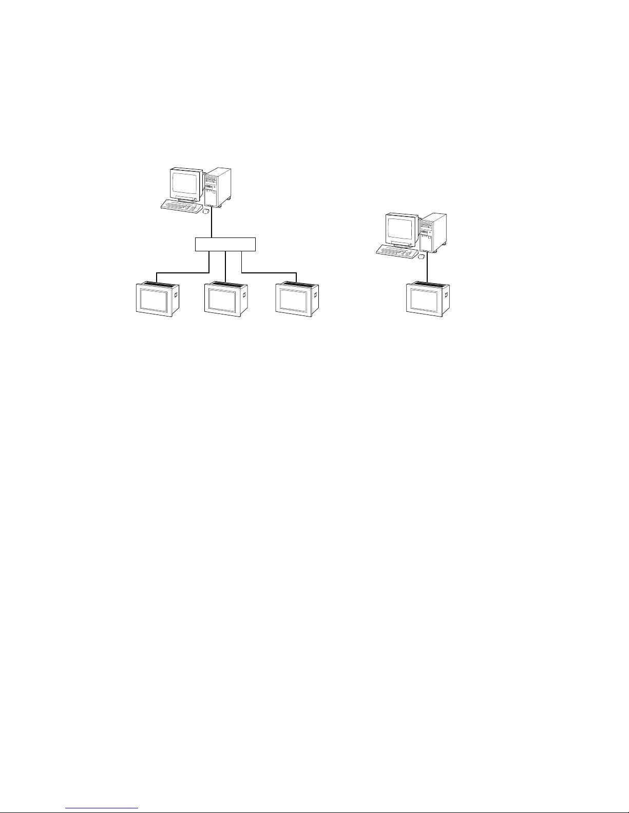
APPENDIX-A ETHERNET CABLE
Different cable types are used depending on how the 7xET and the PC installed with the 7xETBLD are connected via
Ethernet.
CONNECTION VIA ETHERNET HUB/SWITCH
Use a ‘Straight Through’ cable between each device and the hub. (Figure A-1)
DIRECT CONNECTION
Use a ‘Crossover’ cable between the PC and the 7xET. (Figure A-2)
Figure A-1. Figure A-2.
If the 7xETBLD shows “Connect Error” saying Ethernet connection is unavailable, confirm the connection on the
Windows MS-DOS.
Confirm Connect Error type
Page 23
19
7xETBLD USERS MANUAL EM-7353-0003C
7xET
Ethernet
Straight Through Cable
Ethernet
Straight Through Cable
7xET7xET
Hub / Switch
7xET
Ethernet
Crossover Cable
Page 24
20
7xETBLD USERS MANUAL EM-7353-0003C
Page 25

1. What is covered.
M-System Co., Ltd. (“M-System”) warrants, only to the original
purchaser of new M-System products purchased directly from MSystem, or from M-System’s authorized distributors or resellers, for its
own use not for resale, that the M-System products shall be free from
defects in materials and workmanship and shall conform to the specifications set forth in the product catalogue applicable to the M-System
products for the Warranty Period (see Paragraph 5 below for the
Warranty Period of each product).
THE ABOVE WARRANTY IS THE ONLY WARRANTY APPLICABLE TO THE M-SYSTEM PRODUCTS AND IS IN LIEU OF ALL
OTHER WARRANTIES, EXPRESS OR IMPLIED, INCLUDING,
BUT NOT LIMITED TO, ALL IMPLIED WARRANTIES OF MERCHANTABILITY OR OF FITNESS FOR A PARTICULAR PURPOSE.
2. What is not covered.
This warranty does not cover any M-System product which has been:
(1) modified, altered or subjected to abuse, misuse, negligence or
accident; (2) improperly installed or installed in conjunction with any
equipment for which it was not designed; or (3) damaged or destroyed
by disasters such as fire, flood, lightning or earthquake.
In no event shall M-System be liable for any special, incidental, consequential or other damages, costs or expenses (including, but not limited
to, loss of time, loss of profits, inconvenience or loss of use of any
equipment).
3. Remedies.
If a defective product is returned to M-System in accordance with the
procedures described below, M-System will, at its sole option and
expense, either: (1) repair the defective product; (2) replace the
defective product; or (3) refund the purchase price for the defective
product paid by the purchaser. Except as otherwise provided by
applicable state law, these remedies constitute the purchaser’s sole and
exclusive remedies and M-System’s sole and exclusive obligation under
this warranty.
M-SYSTEM WARRANTY
4. Warranty Procedure.
If the purchaser discovers a failure of the M-System products to
conform to the terms of this warranty within the Warranty Period, the
purchaser must promptly (and, in any event not more than 30 days after
the discovery of such failure) notify the relevant party as described
below either by telephone or in writing at the below address to obtain an
Authorized Return (AR) number and return the defective product to the
relevant party. The designated AR number should be marked on the
outside of the return package and on all correspondence related to the
defective product. The purchaser shall return, at purchaser’s expense,
defective products only upon receiving an AR number. In order to avoid
processing delays, the purchaser must include: copies of the original
purchase order and sales invoice; the purchaser’s name, address and
phone number; the model and serial numbers of the returned product;
and a detailed description of the alleged defect.
5. Warranty Period.
Signal Conditioner: 36 months from the date of purchase.
M-Rester: 12 months from the date of purchase.
Valve Actuator: 18 months from the date of shipment from
M-System or 12 months from the date of its
installation, whichever comes first.
Other Products: 36 months from the date of purchase.
M-SYSTEM CO., LTD.
5-2-55, Minamitsumori, Nishinari-ku,
Osaka 557-0063 JAPAN
Phone: (06) 6659-8201
Fax: (06) 6659-8510
E-mail: info@m-system.co.jp
Page 26

1
73ET/74ET/75ET USERS MANUAL EM-7353-0003B Rev.5
PAPERLESS RECORDING SYSTEM
TOUCH PANEL
PAPERLESS RECORDER
Model: 73ET / 74ET / 75ET
Users Manual
Page 27

2
73ET/74ET/75ET USERS MANUAL EM-7353-0003B Rev.5
Contents
1. GENERAL DESCRIPTIONS ........................................................................ 4
1.1 7xET FEATURES & FUNCTIONS ............................................................................................... 4
1.2 SYSTEM CONFIGURATIONS ..................................................................................................... 6
1.3 HARDWARE SPECIFICATIONS ................................................................................................. 7
1.3.1 SYSTEM COMPONENTS................................................................................................ 7
1.3.2 COMPONENT IDENTIFICATION ..................................................................................... 7
1.4 INSTALLATION............................................................................................................................ 9
1.4.1 INSTALLATION REQUIREMENTS .................................................................................. 9
1.4.2 PANEL CUTOUT (unit: mm) ........................................................................................... 10
1.4.3 INSTALLATION PROCEDURE ....................................................................................... 11
1.5 I/O MODULES ........................................................................................................................... 12
1.5.1 INPUT DEVICE SELECTIONS ...................................................................................... 12
1.5.2 CONNECTING I/O MODULES TO THE 7xET ............................................................... 12
1.5.3 CONFIGURING THE R1M, R2M & RZMS-U9 MODULES ............................................ 14
1.6 CF CARD ................................................................................................................................... 16
1.6.1 HOW TO INSERT AND REMOVE THE CF CARD......................................................... 17
1.6.2 REPLACING THE CF CARD ......................................................................................... 17
2. STARTING UP THE 7xET.......................................................................... 18
2.1 MENU OPTIONS ....................................................................................................................... 18
2.2 USING A BLANK CF CARD FOR 74ET & 75ET ....................................................................... 19
2.3 STARTING UP ........................................................................................................................... 19
3. SETTING THE 7xET .................................................................................. 20
3.1 COMMUNICATION SETTING ................................................................................................... 20
3.2 STORING RATE ........................................................................................................................ 20
3.3 DISPLAY RATE.......................................................................................................................... 21
3.4 CHART SPEED ......................................................................................................................... 21
3.5 GRAPH ...................................................................................................................................... 21
3.6 DIGITAL DISPLAY TYPE........................................................................................................... 21
3.7 DIGITAL DISPLAY ..................................................................................................................... 22
3.8 START MODE............................................................................................................................ 22
3.9 TEMPERATURE UNIT .............................................................................................................. 22
3.10 DATA STORING FORM ............................................................................................................. 22
3.11 SCREEN SAVER....................................................................................................................... 23
3.12 DATE TIME................................................................................................................................ 23
3.13 DATA FILE USED VOLUME SETTING ..................................................................................... 23
3.14 CJC (Cold Junction Compensation) SETTING .......................................................................... 24
3.15 DATA STORING METHOD ........................................................................................................ 24
3.15.1 TRIGGER (A) STORING MODE (REMOTE TRIGGER) ................................................ 25
3.15.2 TRIGGER (B) STORING MODE (EVENT RECORDING).............................................. 26
3.15.3 AUTO STORING MODE ................................................................................................ 26
3.16 NODE SETTING ........................................................................................................................ 27
Page 28

3
73ET/74ET/75ET USERS MANUAL EM-7353-0003B Rev.5
3.17 PEN SETTING ........................................................................................................................... 28
3.17.1 PEN SETTING (COMMON) ........................................................................................... 28
3.17.2 PEN SETTING (ANALOG) ............................................................................................. 30
3.17.3 PEN SETTING (ANALOG ALARM) ................................................................................ 35
3.17.4 PEN SETTING (DISCRETE) .......................................................................................... 36
3.17.5 CONFIRMING CHANGES ............................................................................................. 37
4. RECORD .................................................................................................... 38
4.1 TREND VIEW ............................................................................................................................ 38
4.1.1 PEN PANEL ................................................................................................................... 38
4.1.2 CHART ........................................................................................................................... 39
4.1.3 DIGITAL DISPLAY.......................................................................................................... 40
4.1.4 CONTROL BUTTONS.................................................................................................... 41
4.2 OVERVIEW ............................................................................................................................... 42
4.2.1 GROUP & TIME INDICATOR......................................................................................... 42
4.2.2 DATA INDICATORS ........................................................................................................ 43
4.2.3 CONTROL BUTTONS.................................................................................................... 44
4.3 BARGRAPH............................................................................................................................... 44
4.3.1 GROUP & TIME INDICATOR......................................................................................... 45
4.3.2 BARGRAPH ...................................................................................................................45
4.3.3 DIGITAL DISPLAY.......................................................................................................... 46
4.3.4 CONTROL BUTTONS.................................................................................................... 46
4.4 TRIPLE VIEW (74ET & 75ET only) ........................................................................................... 47
5. RETRIEVE.................................................................................................. 48
6 ALARM HISTORY ...................................................................................... 51
7 R5/R3 SERIES I/O MODULES................................................................... 53
7.1 R5-NM1 ..................................................................................................................................... 53
7.1.1 CONFIGURING THE R5-NM1 HARDWARE ................................................................. 53
7.1.2 CONNECTING TO THE 7xET ........................................................................................ 54
7.1.3 SETTING UP THE 7xET SPECIFICALLY FOR R5 SERIES .......................................... 55
7.2 R3-NM1 ..................................................................................................................................... 57
7.2.1 CONFIGURING THE R3-NM1 HARDWARE ................................................................. 57
7.2.2 CONNECTING TO THE 7xET ........................................................................................ 58
7.2.3 SETTING UP THE 7xET SPECIFICALLY FOR R3 SERIES .......................................... 59
8. FILE ............................................................................................................ 61
8.1 7xET FILES ............................................................................................................................... 61
8.2 DATA STORAGE TIME.............................................................................................................. 62
APPENDIX – 1. IP ADDRESS SETTING ........................................................................................... 63
APPENDIX – 2. BACKLIGHT FAILURE ............................................................................................. 63
APPENDIX – 3. VERSION INDICATION ............................................................................................ 63
Page 29

4
73ET/74ET/75ET USERS MANUAL EM-7353-0003B Rev.5
1. GENERAL DESCRIPTIONS
Thank you for choosing M-System’s Paperless Recording System.
The system consists of a 7xET Series Touch Panel Paperless Recorder, Models 73ET, 74ET and 75ET and RxM
Series I/O Modules, Models R1M and R2M. The 7xET Series, with its functions and operability similar to conventional chart recorders, can easily replace them. It is also a flexible and economical solution, in conjunction with
independent I/O modules which can accept either DC voltage/current, thermocouple, or RTD.
Data are stored electronically on a CF Card. Remote recording via Ethernet is also possible using the PC Recorder
Software MSR128.*
This users manual explains how to install the 7xET Series Recorder, connect to the RxM Series I/O Modules and
operate the Paperless Recorder Software on the 7xET Touch Panel.
If you intend to use the 7xET in the following environments or conditions, redundant and/or failsafe system designs
should be used to ensure the proper degree of reliability and safety.
- Environments or conditions which are not defined in this manual
- Nuclear power control devices, railway control devices, aircraft control devices, transportation vehicles,
fuel control equipment, medical equipment, recreational equipment, safety equipment, and other critical
equipment for which safety must be secured according to relevant laws.
- Those devices which inherently require extremely high level of safety and reliability.
*Explanations regarding the MSR128 given in this manual are applicable to the MSR128-V4, Ver 4.00 or higher. For using the MSR128-V4
or even the MSR128 of earlier versions, refer to respective users manuals.
■ COMPACT FLASH (CF) CARD
A CF Card is required to start up the 7xET.
M-System will not guarantee the product’s described performance if a CF Card other than purchased from M-
System, or specified below, is used.
Recommended CF Card: Manufacturer: Hagiwara Sys-Com
Model No.: MCF10P-xxxxS (Alternative Model No. CFI-xxxxDG)
Capacity: 128 MB through 512 MB
1.1 7xET FEATURES & FUNCTIONS
Model 7xET is a touch panel display, installed with M-System’s Paperless Recorder Software. The Windows-CE
based recording/logging system is most suitable for exporting data to other Windows based applications, such as
Microsoft Excel.
The 7xET transfers, in real time via Ethernet, data from local I/O modules connected via Modbus RTU to a host PC
installed with the MSR128 PC Recorder Software. It can also store data in a CF card, portable and usable on an
independent PC for later analysis.
■ DATA RECORDING FUNCTIONS
Number of channels: Max. 128 points from I/O modules connected via RS-232C (Modbus RTU) and expanded
via RS-485
Sampling rate: 0.5 sec.
Storing rate: 0.5 sec., 1 sec., 2 sec., 5 sec., 10 sec., 1 min., or 10 min.
Data form: Binary, floating or short integer
Data storage: CompactFlash (CF) Card
■ DATA DISPLAY FUNCTIONS
• Trend View — Shows data stored in real time on the trend graphs.
Display channels*1: Max. 12 points per view
Display rate: 0.5 sec. or 2 sec.
Chart direction: Vertical or horizontal
Data type: High speed, middle speed, low speed or very low speed
Number of display views: 3 views
Page 30

5
73ET/74ET/75ET USERS MANUAL EM-7353-0003B Rev.5
• Overview — Shows real-time data for all channels.
Display channels: 32 points
Display rate: 0.5 sec. or 2 sec.
Data display items: Analog: Tag name, alarm status, momentary value (bargraph)
Discrete: Tag name, alarm status, momentary value
Detailed data display: Analog: Tag name, momentary value (bargraph + digital indicator), alarm event date/time
(trigger & reset)
Discrete: Tag name, momentary value, alarm event date/time
Used data file volume: Unused data file volume can be indicated.
Number of display views: 4 views
• Bargraph View — Shows data stored in real time on the bargraphs.
Display channels*1: Max. 12 points per view
Display rate: 0.5 sec. or 2 sec.
Bar direction: Vertical or horizontal
Number of display views: 3 views
• Retrieve View — Shows data stored in the CF Card.
Number of display views: 3 views
Time index search: By scrolling the window or by specifying the time index
Engineering unit indicators: When a part of the screen for a specific time index is touched, digital indicators appear on
the screen indicating the data at the specified time.
• Alarm History — Shows alarm event information.
Number of display views: 1 view
Displayed events: 16 events
Data display items: Alarm event date/time (trigger & reset), tag name, pen No., alarm message
Search: By scrolling the window or by specifying the time index
Accept: Individual or all events
Update: Automatic or manual
• Triple View (available with the 74ET and the 75ET only) — Shows Trend, Overview and Alarm History on
the same screen.
• Settings View
■ ALARM
Alarm setting: Analog: Upper (high) and lower (low) alarm setpoints are selectable for each channel.
Discrete: ON or OFF bit status alarm for each channel.
Deadband: Analog: Deadband (hysteresis) is selectable in engineering unit value.
Discrete: Delay time can be specified.
Alarm history record: Stored in the CF Card: Date/time of alarm events (trigger & reset), tag name and pen No.,
alarm message
■ ETHERNET CONNECTIVITY
Ethernet communication: Transmits data of specific channels stored in real time to a host PC installed with the PC
Recorder Software Model MSR128*
2
.
Configurator software (model: 7xETBLD)*2 can be used to set the 7xET parameters.
Number of host PC: Max. 2 PCs
*1. Number of channels depends upon the storing interval and the display interval. The number is limited to four (4)
when either the storing rate or the display rate is set to 0.5 seconds.
*2. Refer to the respective instruction manuals included in the CD-ROM for detailed information.
CAUTION !
Data record may miss certain number of samples if the Ethernet cable is disconnected and reconnected during
recording. Be sure to secure the cable during recording.
Page 31

6
73ET/74ET/75ET USERS MANUAL EM-7353-0003B Rev.5
1.2 SYSTEM CONFIGURATIONS
■R1M, R2M, RZMS
RS-232C
PC Recorder
(model: R1M-GH
or R1MS-GH3)
PC Recorder
(model: R1M-D1)
PC Recorder
(model: R1M-P4)
RS-485
PC Recorder
(model: R1M-A1)
RS-232C
Interlink / Reverse
Cable
PC Recorder
(model: R2M)
RS-232C/RS-485
Converter
(model: R2K-1)
Insert an RS-232C/RS-485 Converter for isolation
to expand the RS-485 line to a long distance.
PC Recorder
(model: RZMS-U9)
Paperless Recorder
(model: 73ET, 74ET, 75ET)
■MONITORING AT THE MSR128-V4 VIA ETHERNET
Paperless Recorder
(models: 73ET, 74ET, 75ET)
RS-485
Ethernet
PC Recorder
(model: R1M-GH)
PC Recorder
(model: R1M-A1)
PC Recorder
(model: R1M-D1)
RS-232C/RS-485 Converter
(model: R2K-1)
Card Reader
CF Card
■READING DATA FROM CF CARD AT THE MSR128-V4
Paperless Recorder
(models: 73ET, 74ET, 75ET)
RS-485
PC Recorder
(model: R1M-GH)
PC Recorder
(model: R1M-A1)
PC Recorder
(model: R1M-D1)
RS-232C/RS-485 Converter
(model: R2K-1)
Page 32

7
73ET/74ET/75ET USERS MANUAL EM-7353-0003B Rev.5
1.3 HARDWARE SPECIFICATIONS
1.3.1 SYSTEM COMPONENTS
■ PAPERLESS RECORDERS (OS: Windows CE 3.0)
73ET: 5.7-inch Touch Panel Unit
74ET: 7.4-inch Touch Panel Unit
75ET: 12.1-inch Touch Panel Unit
■ ACCESSORIES INCLUDED IN THE PRODUCT PACKAGE
Paperless Recorder Software Package (model: CHARTLSP2)
Installation Fasteners
■ ACCESSORIES & RELATED PRODUCTS
Panel Mount Adaptors (for DIN-size panel cutout)
For 73ET: Model A-73
For 74ET: Model A-74
For 75ET: Model A-75
PC Recorder I/O Modules (R1M, R2M and RZMS Series)
Remote I/O Modules (R3 and R5 Series)
1.3.2 COMPONENT IDENTIFICATION
■ 73ET
■FRONT VIEW
■REAR VIEW
■RIGHT SIDE VIEW
Touch Panel
Switching screens, controls
Power Terminals
10BASE-T
Modular Jack
Ethernet interface
■LEFT SIDE VIEW
Power Indicator LED
ON with power supplied.
CF Card Slot
CompactFlash Card interface
RS-232C Connector
I/O interface
FG
–+
FG
NL
Page 33

8
73ET/74ET/75ET USERS MANUAL EM-7353-0003B Rev.5
■ 74ET
■FRONT VIEW
■REAR VIEW
■LEFT SIDE VIEW
10BASE-T Modular Jack
Ethernet interface
Touch Panel
Switching screens, controls
CF Card Slot
CompactFlash Card interface
Status Indicator LED
Green: Power ON/Normal
(Red to Green at startup)
Orange: Backlight failure
Red: System error
Serial Interface (COM1, COM2)
RS-232C connector (COM2 unused)
Power Terminals
Connect to 24V DC
Unidentified connectors and sockets are unused.
Page 34

9
73ET/74ET/75ET USERS MANUAL EM-7353-0003B Rev.5
■ 75ET
1.4 INSTALLATION
1.4.1 INSTALLATION REQUIREMENTS
•For easy maintenance, operation and sufficient ventilation, at the minimum of 100 mm must be observed between
the 7xET unit and adjacent structures or equipment.
Figure 1.4.1a: Maintenance space requirements.
■BOTTOM VIEW
■REAR VIEW
■LEFT SIDE VIEW ■FRONT VIEW
Touch Panel
Switching screens, controls
Status Indicator LED*
Green: Power ON/Normal
(Red to Green at startup)
Orange: Backlight failure
Red: System error
Serial Interface (COM1, COM2)
RS-232C connector (COM2 unused)
Power Terminals
CF Card Slot
CompactFlash Card interface
10BASE-T Modular Jack
Ethernet interface
*Located behind the panel
mount adaptor (if used).
Unidentified connectors and sockets are unused.
100 mm
100 mm
100 mm
100 mm
100 mm
100 mm 100 mm
Paperless Recorder
Page 35

10
73ET/74ET/75ET USERS MANUAL EM-7353-0003B Rev.5
• Ambient temperature: 0 to 50°C (except for 73ET for 0 to 45°C)
Ambient humidity: 30 to 85% RH
Ambient temperature refers to both the temperatures behind the panel and over the panel.
•We recommend to mount the 7xET on a vertical panel. With a slanted panel, the 7xET must not incline more than 30
degrees from the vertical. If the 7xET is to be installed in greater angle, use a forced-air cooling system to maintain
the ambient temperature lower than 50°C.
Figure 1.4.1b: Mounting angle.
• Horizontal (rotated) installation is not allowed.
1.4.2 PANEL CUTOUT (unit: mm)
■ 73ET ■ 74ET
■ 75ET
30°30
°
30° or less
from vertical
156
Panel thickness: 1.6 – 10.0 mm
123.5
+1
0
+1
0
4–R3 max.
Panel thickness: 1.6 – 10.0 mm
204.5
+1
0
159.5
+1
0
4–R3 max.
Panel thickness: 1.6 – 10.0 mm
227.5
+1
0
4–R3 max.
301.5
+1
0
Page 36

11
73ET/74ET/75ET USERS MANUAL EM-7353-0003B Rev.5
1.4.3 INSTALLATION PROCEDURE
■ INSTALLATION GASKET
The 7xET unit should always be installed using the pre-fitted installation gasket, even at locations where water
resistance is not required.
The installation gasket must be installed properly to ensure a sufficient water-resistance level.
When properly installed, the gasket uniformly extends approximately 2 mm out of the groove.
■ INSTALLING THE 7xET ONTO THE PANEL
1. Insert the 7xET unit into the cutout section of the panel with the touch screen facing outward.
2. Insert the installation fastener hooks into the four (4) insertion slots, two (2) on the top and two (2) on the bottom.
3. Slide the fastener toward the rear of the 7xET.
4. Slowly tighten each fastener attachment screw in sequence until all fasteners are evenly and securely tightened.
The appropriate torque for tightening an attachment screw is 0.5 N·m.
For use with Panel Mount Adaptors (models: A-73, A-74, A-75), refer to the respective instructions.
■ CONNECTING TO THE POWER SOURCE
WARNING !
Turn the main power supply off prior to connecting the 7xET power terminals. Failure to do so may result in an
electrical shock.
CAUTION !
Observe the operational voltage range as indicated below . Supplying any other le vel of po wer can damage the 7xET
unit or the power source.
73ET 100 – 240V AC rating: Operational voltage range 85 – 264V AC
24V DC rating: 24V DC ±10%
74ET 24V DC rating: 24V DC ±20%
75ET 24V DC rating: 24V DC ±20%
• Power Supply Cable
To reduce line-to-line and line-to-ground noise as much as possible, use a low-noise power supply.
The wires for the 7xET’s power supply, I/O devices, and any motor-driven equipment must be installed separately.
To increase the noise resistance, use a twisted-pair cable for power supply.
Do not bind together or place near each other the main circuit cables (high voltage and high current), I/O signal
cables, and power supply cables.
To reduce noise, keep the power supply cables as short as possible.
• Grounding
Use a grounding resistance of less than 100Ω.
The grounding for the 7xET unit should be independent of other devices. Use exclusive grounding or a common
grounding point.
Insertion slots
Top view: Two more insertion slots at the bottom.
Installation panel
Hook
Page 37

12
73ET/74ET/75ET USERS MANUAL EM-7353-0003B Rev.5
• Wire Connection
Use thick wires (max. 2 mm
2
) for the power supply. Always start braiding close to the terminal ends.
Use the sleeve-type ring terminals as shown to the right.
Connection Procedure
1. Confirm that the mains supply is off.
2. Remove the ter minal block cover’s attachment screws.
3. Remove the ter minal block cover.
4. Remote the screws from the three (3) middle terminals.
5. Align the power wires (braided) and the grounding (FG).
6. Re-insert and tighten the terminal screws. (Torque 0.5 – 0.6 N·m)
7. Reattach the terminal block cover and tighten its screws. (Torque 0.5 – 0.6 N·m)
1.5 I/O MODULES
1.5.1 INPUT DEVICE SELECTIONS
Table 1.5.1 shows a list of usable I/O modules for the 7xET.
Table 1.5.1: I/O modules usable with the 7xET.
1.5.2 CONNECTING I/O MODULES TO THE 7xET
I/O modules directly next to the 7xET are connected via RS-232C. (Use COM1 only for the 74ET and the 75ET.)
Tables 1.5.2a and 1.5.2b show the RS-232C connector pin assignments.
Table 1.5.2a: 73ET pin assignment. Table 1.5.2b: 74ET and 75ET pin assignment.
max.
6.0 mm
min. ø3.2 mm
1
5
6
9
ABBR.
PIN NO. EXPLANATION OF FUNCTION
1 Not Used.
BB (RD) 2 Received Data
BA (SD) 3 Transmitted Data
CD (ER) 4 DTE Ready
AB (SG) 5 Signal Common
CF (CD) 6 Received Line Signal Detector
CA (RS) 7 Request to Send
CB (CS) 8 Clear to Send
9 Do Not Connect.
ABBR.
PIN NO. EXPLANATION OF FUNCTION
CF (CD) 1 Received Line Signal Detector
BB (RD) 2 Received Data
BA (SD) 3 Transmitted Data
CD (ER) 4 DTE Ready
AB (SG) 5 Signal Common
CC (DR) 6 Data Set Ready
CA (RS) 7 Request to Send
CB (CS) 8 Clear to Send
CE (CI) 9 Calling Indicator
MODEL R1M R2M RZMS-U9 R3-NM1 R5-NM1
DC Voltage
R1M-GH2*
1,*2
R2M-2G3*
3
R3-SV R5-SV
Analog DC Current
R1MS-GH3*1,*
3
No R3-SS/-DS R5-SS/-DS
Input Thermocouple R2M-2H3*
3
RZMS-U9*1,*3R3-TS R5-TS
RTD R1M-J3 No R3-RS R5-RS
Potentiometer No No
CT No No No R3-CT No
PT No No No R3-PT No
Contact Input R1M-A1 No No R3-DA R5-DA
Contact Output
R1M-D1
No No R3-DC R5-DC
(open collector)
Pulse Input (totalizing counter)
R1M-P4
No No No No
R1M-A1C1
*1. Resistor module (model: REM3-250) is required to convert the current signal into voltage.
*2. Trigger contact input (1 point) is available.
*3. Trigger contact input (1 point) and alarm contact output (1 point) are available.
Page 38

13
73ET/74ET/75ET USERS MANUAL EM-7353-0003B Rev.5
The R1M/R2M is connected to 7xET’s COM port via a straight RS-232C cable included in the product package.
Second and more R1M, up to 15 in total, can be connected via RS-485 twisted-pair cables as shown in Figure 1.5.2.
When the line between the R1M and the PC needs to be extended via RS-485, insert an RS-232C/RS-485 converter
(model: R2K-1) to prevent noise interference and connect the converter to the PC via a straight RS-232C cable.
If you need to connect an R2M module with an R1M module on the RS-485 network, use an RS-232C interlink/
reverse cable.
Figure 1.5.2: System configuration example for the R1M/R2M series.
RS-485, Modbus RTU
RS-232C
straight
RS-485
RS-232C
Interlink/reverse
R1M-GH2
DC/TC INPUTS
16 points
1 trigger input
R2K-1
R2M-2H3
TC INPUTS
8 points
7xET
R1M-J3
RTD/POT INPUTS
8 points
R1M-A1
CONTACT INPUTS
32 points
R1M-D1
CONTACT OUTPUTS
(open collector)
32 points
Page 39

14
73ET/74ET/75ET USERS MANUAL EM-7353-0003B Rev.5
1.5.3 CONFIGURING THE R1M, R2M & RZMS-U9 MODULES
MODEL R1M-GH2
The Model R1M-GH2 needs hardware setting to specify the type/level of input signals.
Figure 1.5.3a: R1M-GH2 bottom view.
Table 1.5.3a: R1M-GH2 DIP switch setting.
SW311 SW305 SW304 SW303 SW302
SW405 SW404 SW403 SW402
SW301
O
N
2
1
3
4
5
6
7
8
SW702
SW702 is fixed to
the position 3.
DO NOT CHANGE.
SW411 SW401 SW308 SW307 SW306
SW408 SW407 SW406
O
N
2
1
3
4
5
6
7
8
INPUT SWITCHES SETTING NOTES
Thermocouple SW301 – SW308 (ch 1 – ch 8) Set to position "1." Attentuation OFF
SW401 – SW408 (ch 9 – ch 16)
SW311 (ch 1 – ch 8) OFF
SW411 (ch 9 – ch 16)
Voltage input, 0.8 V or less SW301 – SW308 (ch 1 – ch 8) Set to poisition "1." Attentuation OFF
SW401 – SW408 (ch 9 – ch 16)
SW311 (ch 1 – ch 8) ON
SW411 (ch 9 – ch 16)
Voltage input, above 0.8 V * SW301 – SW308 (ch 1 – ch 8) Set to position "3." Attentuation ON
SW401 – SW408 (ch 9 – ch 16)
SW311 (ch 1 – ch 8) ON
SW411 (ch 9 – ch 16)
*Factory default setting
Page 40

15
73ET/74ET/75ET USERS MANUAL EM-7353-0003B Rev.5
MODEL R1M-P4
The Model R1M-P4 needs hardware setting to specify the display type for either totalized or momentary value.
Figure 1.5.3b: R1M-P4 bottom view.
MODEL RZMS-U9
The Model RZMS-U9 needs hardware setting to specify the A/D conversion mode, service channel numbers, cold
junction compensation, line noise filter frequency , and burnout type for temperature inputs . Cold junction compensation could be specified on the 7xET program.
Switch Positions
1 through F: At the startup, the combination of settings as shown in the table below is enabled.
0: PC configuration mode (PC Configuration Software RZMSCFG, under development).
At the startup, last software setting before the power is turned off is enabled.
Figure 1.5.3c: RZMS-U9 rear view.
Table 1.5.3b: RZMS-U9 rotary switch setting.
SW602
SW602 is fixed to
the position 3.
DO NOT CHANGE.
Momentary
SW604
Totalized
(factory default)
Totalized or Momentary
Display Selector
RS-485 Connector
Configurator Jack
Address Setting
Rotary SW
Operating Mode
Setting Rotary SW
RS-232C
9-pin Connector
Power / FG Terminals
A/D SERVICE COLD JUNCTION
LINE NOISE
BURNOUT (T/C and RTD)
CONVERSION CHANNEL COMPENSATION FILTER All Channels
Individual
MODE NUMBERS (T/C)
FREQUENCY
NONE UP DOWN
Channels
With 50/60 Hz 1 2 3
50 Hz 4 5 6
Medium 12 60 Hz 7 8 9
Without 50 Hz A B C
60 Hz D E F
Software setting Software setting Software setting Software setting 0
for all channels (12 or 6) for individual for all channels Software
(
Fast, Medium, Slow
) channels (50, 60, 50/60 Hz) setting
Remark 1: Factory setting is ‘1.’
Page 41

16
73ET/74ET/75ET USERS MANUAL EM-7353-0003B Rev.5
RS-485
Connector
Power Terminals
Address Setting
Rotary SW
Configurator
Jack
Specification Label
RS-232C
9-pin Connector
Configurator
Jack
RS-232C
9-pin Connector
Address Setting
Rotary SW
NODE NUMBER
Node number setting (1 – F, up to 15 nodes) is required at the rear rotary switch when more than one module is
connected. Each module must ha ve an unique node n umber . Before changing the node number, be sure to turn off
the power supply to the module.
Figure 1.5.3d: R1M rear view. Figure 1.5.3e: R2M rear view.
Figure 1.5.3f: RZMS-U9 rear view.
1.6 CF CARD
A CF Card is required to operate the 7xET. Use one manufactured by Hagiwara Sys-Com. Recommended card
types are indicated under Section 1. GENERAL DESCRIPTIONS.
CAUTION !
• DO NOT extract the CF Card while recording.
• The 7xET may still be accessing the CF Card for a while after the recording has been stopped. DO NOT remove
power to the 7xET while recording and immediately after the recording has been stopped (1 or 2 minutes).
•Prior to inserting the CF Card, carefully check the orientation of the CF Card (front face) and the connector. Incorrect
orientation may damage the card or destroy its data.
Figure 1.6: CF card dimensions and front/reverse sides identification.
RS-485 Connector
Configurator Jack
Address Setting
Rotary SW
Operating Mode
Setting Rotary SW
RS-232C
9-pin Connector
Power / FG Terminals
42.80 ±0.10 mm
36.40 ±0.08 mm
Wide Narrow
FRONT SIDE
The CF Card is keyed with guide grooves of uneven width at
each side in order to prevent insertion in an wrong orientation.
Page 42

17
73ET/74ET/75ET USERS MANUAL EM-7353-0003B Rev.5
1.6.1 HOW TO INSERT AND REMOVE THE CF CARD
73ET , Inserting
1. Locate the CF Card cover at the rear. Loosen the cover screws and remove the cover.
2. Check the orientation of the CF Card first referring to Figure 1.6.1a and insert it into the CF Card slot until the Eject
button pops forward.
3. Close the CF Card cover and tighten it with the screws.
Figure 1.6.1a: 73ET, Inserting the CF Card.
73ET, Removing
1. Locate the CF Card cover at the rear. Loosen the cover screws and remove the cover.
2. Push the Eject button until the CF Card pops forward.
3. Close the CF Card cover and tighten it with the screws.
74ET & 75ET , Inserting
1. Push the cover in the direction indicated by the t and lift it open.
2. Check the orientation of the CF Card first referring to Figure 1.6.1a and insert it into the CF Card slot until the Eject
button pops forward.
3. Close the CF Card cover and push it in the direction shown by the ▼ until it click shut.
74ET & 75ET, Removing
1. Push the cover in the direction indicated by the ▼ and lift it open.
2. Push the Eject button until the CF Card pops forward.
3. Close the CF Card cover and push it in the direction shown by the ▼ until it click shut.
Figure 1.6.1b: 74ET, Inserting the CF Card. Figure 1.6.1c: 75ET, Inserting the CF Card.
1.6.2 REPLACING THE CF CARD
When you need to replace the CF Card, copy the contents of the original CF Card (software 74ETxxx.exe* or
75ETxxx.exe*, and Bac kup folder) to the new card. Insert a new card to the 7xET and turn on the power supply. *xxx
= Software version No.
Remark: The 73ET does not need the above procedure. Just insert the new card and restart the 73ET. Configuration setup file (7xET.7xPA) can be copied from previous CF card.
Eject Button
Front Face
Eject Button
Front Face
Eject Button
Screen
Front Face
Page 43

18
73ET/74ET/75ET USERS MANUAL EM-7353-0003B Rev.5
2. STARTING UP THE 7xET
2.1 MENU OPTIONS
Figure 2.1 shows a map of various options available on the 7xET.
Figure 2.1: 7xET options list.
Stop
Node setting
Pen setting (Common)
Pen setting (Analog)
Pen setting (Analog alarm)
Pen setting (Discrete)
Page Up
1/4 Up
1/4 Down
Page Down
Group Change
Date Time
Pen Select
Record Trend View
Bargraph
Overview
Triple View
Retrieve Page Up
1/4 Up
1/4 Down
Page Down
Date Time
Acknowledge All
Auto Update
Record Trend
Bargraph
Overview
Triple View
Alarm History
Normal
Trigger (A)
Auto
Data storing method
Trigger (B)
No storing
Start
Retrieve
Alarm History
Pen Select
Trend View
Bargraph
Overview
Triple View
Setting
Trend View
Bargraph
Overview
Triple View
*
*
*Available only with the 74ET and the 75ET.
*
Page 44

19
73ET/74ET/75ET USERS MANUAL EM-7353-0003B Rev.5
2.2 USING A BLANK CF CARD FOR 74ET & 75ET
For the 74ET or the 75ET, you need to copy files required to operate the 7xET to your blank CF Card. For the 73ET,
no copying files are required.
Required files are stored under the following directories in the PC Recorder Software Package CD (model:
CHARTLSP2).
74ET: \Softw are\74ET(English)
75ET: \Softw are\75ET(English)
Each folder contains an .exe file and a Backup folder. Copy both of them to the CF Card. The property of files in
Backup folder is set to ‘Read Only.’ Remove these settings. (Select ‘Apply changes to this folder, sub-folders and
files.’)
Remark 1: 74ET/75ET Backup folders exist for English and Japanese. Files in 74ET(Japanese) or 75ET(Japanese)
folders are not usable.
Remark 2: With the Windows XP, the ‘Read Only’ setting of the folder is automatically reset when files are copied to
the CF Card. ‘Read Only’ box in the ‘Proper ty’ is marked with ■, which indicates the folder is NOT ‘Read Only.’
However, files in the folder may still be ‘Read Only.’ In that case, Set ‘Read Only’ box to blank and select ‘Apply
changes to this folder, sub-folders and files.’
2.3 STARTING UP
When the power supply to the 7xET is turned on after the CF Card has been set, Initial Check view appears on the
screen. The view is sho wn while the 7xET is creating the data file in the CF Card. After that, the initial view as shown
in Figure 2.3 appears on the screen.
Remark: The 7xET does not start up unless the CF Card is inserted before the power is turned on.
Figure 2.3: Initial view while stand-by.
CAUTION !
The 7xET may require a certain time after a control button is touched until the designated action or setting is complete. Operate the 7xET control buttons slowly and confirm each step of operation before going to a next step.
Hasty operation may damage the CF Card.
Page 45

20
73ET/74ET/75ET USERS MANUAL EM-7353-0003B Rev.5
3. SETTING THE 7xET
Touching Setting button on the initial view opens Setting view which consists of two pages. Figure 3a shows the first
page.
Touching Page button turns the page of the Setting view to show the second page (Figure 3b).
Touch Record and return to the Record view in order to apply the new setting.
Figure 3a: Setting view, Page 1. Figure 3b: Setting view, Page 2.
In order to enable new setting, press Record button and go back to Record View (Trend, Overview or Bargraph).
3.1 COMMUNICATION SETTING
Touching the current selection of the Communication Setting shows selectable options at the bottom of the screen
(Figure 3.1).
DEMO: You can run the 7xET program without actual signal input for learning, evaluation and demonstration
when you choose DEMO.
RxM: Choose this option when you connect R1M/R2M via Modbus RTU.
Cancel button is used for returning to the Setting view without any change in the Communication Setting.
Figure 3.1: Communication setting.
3.2 STORING RATE
Touching the current selection of the Storing Rate shows selectable options at the bottom of the screen (Figure 3.2).
Choose among 0.5 sec., 1 sec., 2 sec., 5 sec., 10 sec., 1 min., and 10 min.
Total recording time depends upon the storing rate selection. Selecting greater storing rate allows longer recording
time, though the data are more thinned, which may jeopardize the data accuracy.
Number of nodes, alarm output setting and other factors may affect the smallest possible rate.
CAUTION !
When the storing rate setting is changed, previously stored data are overwritten with new data.
Figure 3.2: Storing rate.
Page 46

21
73ET/74ET/75ET USERS MANUAL EM-7353-0003B Rev.5
3.3 DISPLAY RATE
Touching the current selection of the Display Rate shows selectable options at the bottom of the screen (Figure 3.3).
Choose between 0.5 sec. and 2 sec.
When you choose 0.5 sec. for the storing rate and/or the display rate, number of pens plottable on the Record view
is limited to four (4) pens, while twelve (12) pens can be plotted at once in any other combination of the two rates.
Figure 3.3: Display rate.
3.4 CHART SPEED
Touching the current selection of the Chart Speed shows selectable options at the bottom of the screen (Figure 3.4).
Choose among High, Middle, Low and Very Low.
When you choose 0.5 sec. for the storing rate and/or the display rate, only High speed is selectable.
Table 3.4. shows the screen time frame by display types at various chart speed settings.
This option can be changed while recording.
Figure 3.4: Chart speed.
Table 3.4: Screen time frame v.s. chart speed.
3.5 GRAPH
Touching the current selection of the Graph shows selectable options at the bottom of the screen (Figure 3.5) to
specify the plotting direction, Perpendicular or Horizontal.
This option can be changed while recording.
Figure 3.5: Graph.
3.6 DIGITAL DISPLAY TYPE
Touching the current selection of the Digital Display Type shows selectable options at the bottom of the screen
(Figure 3.6a) to specify either to show only the tag name or the value, or both.
Figure 3.6a: Digital Display Method.
The momentary value and The tag name of the data The momentary value of
the tag name of the data plotted on the screen. the data plotted on the screen.
plotted on the screen.
Figure 3.6b: Tag + Value. Figure 3.6c: Tag. Figure 3.6d: Value.
73ET 74ET 75ET
Perpendicular Horizontal Perpendicular Horizontal Perpendicular Horizontal
W/O W/ ---- W/O W/ ---- W/O W/ ----
Digital Meters Digital Meters Digital Meters Digital Meters Digital Meters Digital Meters
High 20 sec 12 sec 27 sec 40 sec 24 sec 54 sec 50 sec 30 sec 1 min/8 sec
Middle 1 min/40 sec 1 min 2 min/15 sec 3 min/20 sec 2 min 4 min/30 sec 4 min/10 sec 2 min/30 sec 5 min/40 sec
Low 6 min/40 sec 4 min 9 min 13 min/20 sec 8 min 18 min 16 min/40 sec 10 sec 22 min/40 sec
Very Low 53 min/20 sec 32 min 72 min
106 min/40 sec
64 min 144 min
133 min/20 sec
80 min
181 min/20 sec
Page 47

22
73ET/74ET/75ET USERS MANUAL EM-7353-0003B Rev.5
3.7 DIGITAL DISPLAY
Touching the current selection of the Digital Display shows selectable options at the bottom of the screen (Figure
3.7) to show or hide the digital display on the Record view.
Auto hide: Digital display is automatically hidden in 30 seconds after it appears on the screen. Touch the
area of the display to call it up.
Continuous: Digital display remains on the screen.
This option can be changed while recording.
Figure 3.7: Digital Display.
3.8 START MODE
Touching the current selection of the Start Mode shows selectable options at the bottom of the screen (Figure 3.8).
Cold Start: At a restart, the 7xET stands by showing the initial view.
Hot Start: At a restart, the 7xET automatically starts recording.
Figure 3.8: Start mode.
3.9 TEMPERATURE UNIT
Touching the current selection of the Temperature Unit shows selectable options at the bottom of the screen (Figure
3.9).
C: Celsius
F: Fahrenheit
Figure 3.9: Temperature unit.
3.10 DATA STORING FORM
Touching the current selection of the Data Storing Form shows selectable options at the bottom of the screen (Figure
3.10).
Floating point 1 data size: 4 bytes
Decimal fraction: max. 4 decimal places (effective number of digits: 6 or 7)
Short integer 1 data size: 2 bytes
Decimal fraction: max. 1 decimal place
Figure 3.10: Data storing form.
Float (floating point) is to be selected when you need to store data including decimal fractions. The 4-b yte-long data
is better in data precision but the total storable time in the CF Card becomes shorter compared from Short Int.
Short int (short integer) is integer data multiplied by 10. The 2-byte-long data is not as precise (one decimal place)
as Float type is, but the total storable time in the CF Card is longer.
For models R1M-P4 or R1M-A1C1 with totalized pulse input, choose Float.
Page 48

23
73ET/74ET/75ET USERS MANUAL EM-7353-0003B Rev.5
WHICH FORM TO CHOOSE? -- EXAMPLE
If you have selected Short integer, and when an input range 1 – 5V is converted in an engineering unit range of 0 –
10, the actual converted values are: 0 at 1V input, 0.25 at 1.1V. In this case, the 7xET can store only one decimal
place, and ‘0.25’ is saved only as ‘0.2.’ Likewise, the input 1.15V is converted into 0.275 in the engineering unit
range, but is saved also as ‘0.2.’ 1.1V and 1.15V inputs make no difference in the short integer form.
Choose Float if you want to make difference between 1.1V and 1.15V.
WARNING !
When the data storing form setting is changed, new data stored in the same data file overwrite previously stored
data.
3.11 SCREEN SAVER
Touching the current selection of the Screen Saver shows a numeric keypad at the bottom of the screen (Figure
3.11).
Enter a desired time in minutes to initiate the screen saver. With the time set to zero (0), the screen saver is
deactivated.
Touching the screen cancel the screen saver mode. The screen saver is automatically cancelled when an alarm is
output.
Figure 3.11: Numeric keypad.
3.12 DATE TIME
Touching the current time setting shows the clock adjustment window at the bottom of the screen (Figure 3.12).
Touching ‘ + ’ or ‘ – ’ button increases or decreases the figure by one (1) increment. ‘00’ button resets the figure to 00.
‘+10’ or ‘-10’ button increases or decreases the figure by ten (10).
Touch OK button to enable the new setting.
Remark: Y ear setting is av ailable from 2000 to 2079 f or the 73ET, from 2000 to 2059 for the 74ET and 75ET. Beyond
these limits, no date time setting is available.
Figure 3.12: Date time.
3.13 DATA FILE USED VOLUME SETTING
The Overview can show a bargraph how much volume of the data file has been used.
The data file is automatically created when the 7xET has started up. 0% is shown when there is no data in the file.
Used-up rate is shown in the percentage of the total volume. For detailed information refer to Section 8.
Figure 3.13a: Data file used volume.
Figure 3.13b: Data file used volume bargraph.
Page 49

24
73ET/74ET/75ET USERS MANUAL EM-7353-0003B Rev.5
3.14 CJC (Cold Junction Compensation) SETTING
Touching CJC Setting button on the Setting view opens CJC Setting view (Figure 3.14).
The cold junction compensation setting is valid only for thermocouple input modules, factory set to ON (pink button
color) for all channels. Be careful to change these settings, only when necessary.
In order to disable the CJC to a particular channel, touch the pink button to the right of each channel number and turn
it to green. In order to enable, touch the green button again and turn it to pink.
For enabling these settings to models R1MS-GH3 and RZMS-U9, the operating mode setting switch at the rear of
these modules must be set to ‘0’ and then re-started.
Figure 3.14: CJC setting.
3.15 DATA STORING METHOD
Touching Data Storing Method button on the Setting view opens Data Storing Method view (Figure 3.15a).
Figure 3.15a: Data storing method.
Page 50

25
73ET/74ET/75ET USERS MANUAL EM-7353-0003B Rev.5
Touching the current selection of the Data Storing Method shows selectable options at the bottom of the screen
(Figure 3.15b).
No storing: Sampled data are plotted on the screen but no recording is executed.
Normal: Recording is manually initiated and stopped. Data is continuously stored while the recording is on.
Trigger (A): Remote trigger. Data is automatically recorded while the external trigger condition (input) is true.
Trigger (B): Event Recording. The 7xET detects an e xternal ev ent by trigger signal, and stores preset number
of samples before and after the moment of event.
Auto: Recording is automatically initiated and stopped at a predefined time.
Figure 3.15b: Data storing method options.
Auto, Trigger (A) and Trigger (B) options require more detailed setting as explained below.
3.15.1 TRIGGER (A) STORING MODE (REMOTE TRIGGER)
Selecting Trigger (A) shows detailed items to be specified for Remote Tr igger Mode (Figure 3.15.1a).
Figure 3.15.1a: Trigger (1) storing mode.
Data is automatically recorded while the external trigger condition (input) is true.
Condition: Specify whether the recorder should identify On or Off of the contact signal as trigger condi-
tion. For example, when the Condition is set to On, the 7xET stores data while the signal is On
and stops recording when it is turned to Off.
Node Number: Specify which R1M/R2M de vice connected to the 7xET is used to trigger . Enter numbers and
alphabets on the alphanumeric keypad which opens by touching the current selection (Figure
3.15.1b)
Figure 3.15.1b: Alphanumeric keypad.
Page 51

26
73ET/74ET/75ET USERS MANUAL EM-7353-0003B Rev.5
3.15.2 TRIGGER (B) STORING MODE (EVENT RECORDING)
Selecting Trigger (B) shows detailed items to be specified for Event Recording Mode (Figure 3.15.2a).
Figure 3.15.2: Trigger (B) storing mode.
Recording is automatically initiated according to predetermined trigger conditions and preset number of samples
before and after the moment of event are stored.
Condition: Specify whether the recorder should identify a rise or sink of the contact signal as trigger.
Node Number: Specify which R1M/R2M de vice connected to the 7xET is used to trigger . Enter numbers and
alphabets on the alphanumeric keypad which opens by touching the current selection (Figure
3.15.1b)
Pretrigger / Posttrigger: 1200 samples at the maximum for each can be stored. Specify numbers of samples to
be stored before (Pretrigger) and after (Posttrigger) the event respectively.
Pretrigger recording is applicable only when the storing rate is set to 0.5 or 1 sec.
3.15.3 AUTO STORING MODE
Selecting Auto shows detailed items to be specified for Auto Storing Mode (Figure 3.15.3).
Figure 3.15.3: Auto storing mode.
Page 52

27
73ET/74ET/75ET USERS MANUAL EM-7353-0003B Rev.5
Choose either ‘One Time Only’ or ‘Every Day’ under Condition option.
One Time Only: Data is stored once at a predefined time. Specify Year-Month-Day and Hour-Min-Sec. to start
the recording and the time duration.
Every Day: The 7xET runs recording once per day at a predefined time. Specify Hour-Min-Sec. to start the
recording and the time duration.
Touching the current selection opens a numeric keypad to enter a new setting.
3.16 NODE SETTING
Touching Node Setting button on the Setting view opens Node Setting view (Figure 3.16).
Figure 3.16: Node setting.
Touch the node number and choose ‘Enable.’ Touching Enable button calls up Modbus Module Type button on the
right side.
R1M-GH2 16-point DC/thermocouple input
R1M-J3 8-point RTD/potentiometer input
R1M-A1 32-point discrete input
R1M-A1C1 32-point discrete input, FCN type connector
R1M-D1 32-point discrete output
R1M-D1C1 32-point discrete output, FCN type connector
R1M-P4(–) Pulse totalizing counter input; detecting pulse edges to rise
R1M-P4(+) Pulse totalizing counter input; detecting pulse edges to sink
R1MS-GH3 8-point isolated DC/thermocouple input
RZMS-U9 12-point isolated universal input
R1M-D1 32-point discrete output, FCN type connector
R2M-2H3 8-point thermocouple input
R2M-2G3 8-point DC input
R5-NM11* R5 series I/O modules, data allocation mode 1
R5-NM12* R5 series I/O modules, data allocation mode 2
R3-NM1* R3 series I/O modules
*Setting the 7xET for R5/R3 Series I/O modules is explained in Section 7.
Page 53

28
73ET/74ET/75ET USERS MANUAL EM-7353-0003B Rev.5
3.17 PEN SETTING
3.17.1 PEN SETTING (COMMON)
Touching Pen Setting (Common) button on the Setting view opens Select Pen Number view (Figure 3.17.1a).
Figure 3.17.1a: Select pen number.
Choose a pen number to set detailed specifications for the pen (Figure 3.17.1b).
Figure 3.17.1b: Pen setting (common).
Enable / Disable
Use this button to enable or disable each pen. The CF Card records data for the enabled pens only.
Analog (Pulse) / Discrete
Choose the signal characteristic for the pen. For the totalized counter input with the R1M-A1C1 and R1M-P4,
specify ‘Analog.’
Page 54

29
73ET/74ET/75ET USERS MANUAL EM-7353-0003B Rev.5
Tag
Touching the current selection opens an alphanumeric keypad (Figure 3.17.1c). ‘A/a’ button switches capital/small
letters (Figure 3.17.1d). Enter up to 8 characters.
Figure 3.17.1c: Alphanumeric keypad (capital letter).
Figure 3.17.1d: Alphanumeric keypad (small letter).
Unit
Touching the current selection opens an alphanumeric keypad. Enter up to 4 characters.
Remark: DO NOT set an engineering unit for the R1M-P4 or R1M-A1C1 with totalized counter input. If you do, a part
of the LSB character may be chip off.
Node Number
Touching the current selection opens an alphanumeric keypad. Specify the node number assigned to the pen.
Channel Number
Touching the current selection opens an alphanumeric keypad. Specify the channel number assigned to the pen.
See the table below for R1M-P4.
R1M-P4 Indicator 7xET Channel
1 thr. 8 (contact I/O) 1 thr. 8
A9
B10
C11
D12
Color
Touching the current selection opens a color palette. Choose a composition of R, G and B on the palette. The
composed color is displayed on the right top corner of the palette.
This option can be changed while recording.
Wide Line
Choose the pen thickness between Normal and Wide.
Page 55

30
73ET/74ET/75ET USERS MANUAL EM-7353-0003B Rev.5
3.17.2 PEN SETTING (ANALOG)
Touch Pen Setting (Analog) button on the Setting view or Analog button on P en Setting (Common) view f or a specific
pen to configure each analog type channel on the Pen Setting (Analog) view (Figure 3.17.2a).
Figure 3.17.2a: Pen setting (analog).
Analog Type
Input selections available to the input module type designated by Node Setting appears in the field. Be sure to set
Node and Channel numbers before the Analog Type setting in order to get appropriate selections.
Figure 3.17.2b: Analog input type selection for R1M-GH2.
Page 56

31
73ET/74ET/75ET USERS MANUAL EM-7353-0003B Rev.5
For the R1M-P4 and R1M-A1C1, input type selections are as shown in Figure 3.17.2c and 3.17.2d.
COUNT: Reads totalized counter value.
PULSE: Reads as momentary value counted in 1 sec. intervals.
For the R1M-A1C1, only COUNT is available.
Figure 3.17.2c: Analog input type selection for R1M-P4.
Figure 3.17.2d: Analog input type selection for R1M-A1C1.
For the RZMS-U9, the Pen Setting (Analog) view consists of two pages. The first page is shown in Figure 3.17.2e
and touching Page button at the bottom switches the view to the second page as shown in 3.17.2f.
Figure 3.17.2e: RZMS-U9, Page 1. Figure 3.17.2f: RZMS-U9, Page 2
Page 57

32
73ET/74ET/75ET USERS MANUAL EM-7353-0003B Rev.5
Available input types for models R1M and R2M are shown in Table 3.17.2a, and for model RZMS-U9 in Table
3.17.2b
Table 3.17.2a: Input types for R1M and R2M.
MODEL I/O TYPE SELECTIONS DEF AULT USABLE RANGE NOTE
R1M-GH2 DC input -20 – 20 V 0 – 20 V -22.7 – 22.7 V ATT SW ON
-5 – 5 V 1 – 5 V -5.6 – 5.6 V ATT SW ON
-1 – 1 V 0 – 1 V -1.4 – 1.4 V ATT SW ON
-800 – 800 mV 0 – 500 mV -860 – 860 mV
-200 – 200 mV 0 – 100 mV -215 – 215 mV
-50 – 50 mV 0 – 50 mV -53 – 53 mV
-10 – 10 mV 0 – 10 mV -13.4 – 13.4 mV
R2M-2G3 DC input -10 – 10 V -10 – 10 V
R1MS-GH3 DC input -10 – 10 V -10 – 10 V
°C °F
R1M-GH2 T/C input (PR) 0 – 1770 32 – 3218
R2M-2H3 K (CA) -270 – 1370 -454 – 2498
R1MS-GH3 E (CRC) -270 – 1000 -454 – 1832
J (IC) -210 – 1200 -346 – 2192
T (CC) -270 – 400 -454 – 752
B (RH) 100 – 1820 212 – 3308
R -50 – 1760 -58 – 3200
S -50 – 1760 -58 – 3200
C (WRe 5-26) 0 – 2320 32 – 4208
N -270 – 1300 -454 – 2372
U -200 – 600 -328 – 1112
L -200 – 900 -328 – 1652
P (Platinel II) 0 – 1395 32 – 2543
R1M-J3 RTD input JPt 100 (JIS ’89) -200 – 500 -328 – 932
Pt 100 (JIS ’89) -200 – 660 -328 – 1220
Pt 100 (JIS ’97/DIN/IEC)
-200 – 850 -328 – 1562
Pt 50Ω (JIS ’81) -200 – 649 -328 – 1200
Ni 508.4Ω -50 – 280 -58 – 536
Pt 1000 -200 – 850 -328 – 1562
POT input 0 –100 Ω 0 – 100 % 0 – 100 %
0 – 500 Ω 0 – 100 % 0 – 100 %
0 – 1k Ω 0 – 100 % 0 – 100 %
0 – 10k Ω 0 – 100 % 0 – 100 %
R1M-D1 DO
R1M-P4 DO
R1M-A1 DI
R1M-P4 DI
R1M-P4 Counter COUNT 0 – 999,999,999 0 – 999,999,999
PULSE 0 – 10000 0 – 10000
R1M-A1C1 Counter COUNT 0 – 999,999,999 0 – 999,999,999
Page 58

33
73ET/74ET/75ET USERS MANUAL EM-7353-0003B Rev.5
MODEL I/O TYPE SELECTIONS DEF AULT USABLE RANGE NOTE
DC input -60 – 60 mV 0 – 60 mV -60 – 60 mV
-125 – 125 mV 0 – 125 mV -125 – 125mV
-250 – 250 mV 0 – 250 mV 250 – 250 mV
-500 – 500 mV 0 – 500 mV -500 – 500 mV
-1000 – 1000 mV 0 – 1000 mV -1000 – 1000 mV
-3 – 3 V 0 – 3 V -3 – 3 V
-6 – 6 V 0 – 6 V -6 – 6 V
-12 – 12 V 0 – 12 V -12 – 12 V
°C °F
RZMS-U9 T/C input (PR) 0 – 1770 32 – 3218
K (CA) -270 – 1370 -454 – 2498
E (CRC) -270 – 1000 -454 – 1832
J (IC) -210 – 1200 -346 – 2192
T (CC) -270 – 400 -454 – 752
B (RH) 100 – 1820 212 – 3308
R -50 – 1760 -58 – 3200
S -50 – 1760 -58 – 3200
C (WRe 5-26) 0 – 2320 32 – 4208
N -270 – 1300 -454 – 2372
U -200 – 600 -328 – 1112
L -200 – 900 -328 – 1652
P (Platinel II) 0 – 1395 32 – 2543
RTD input Pt 100 (JIS ’89) -200 – 660 -328 – 1220
Pt 100 (JIS ’97/DIN/IEC)
-200 – 850 -328 – 1562
Pt 200 -200 – 850 -328 – 1562
Pt 300 -200 – 850 -328 – 1562
Pt 400 -200 – 850 -328 – 1562
Pt 500 -200 – 850 -328 – 1562
Pt 1000 -200 – 850 -328 – 1562
Pt 50Ω (JIS ’81) -200 – 649 -328 – 1200
JPt 100 (JIS ’89) -200 – 510 -328 – 950
Ni 100 -80 – 260 -112 – 500
Ni 200 -80 – 260 -112 – 500
Ni 508.4 -50 – 280 -58 – 536
Ni-Fe 604 -200 – 200 -328 – 392
Cu 10 @25°C -50 – 250 -58 – 482
POT input 0 –200 Ω 0 – 100 % 0 – 100 %
0 – 500 Ω 0 – 100 % 0 – 100 %
0 – 5k Ω 0 – 100 % 0 – 100 %
Table 3.17.2b: Input types for RZMS-U9.
Input Range
Specify within the actual upper and lower default ranges referred to as 0% (left field) and 100% (right field) respectively. Touching each field opens a numeric keypad as shown in Figure 3.17.2g. Entered v alue is shown on the right
top.
For a thermocouple and RTD input, Input Range is fixed and equal to the maximum default range.
Figure 3.17.2g: Numeric keypad.
Page 59

34
73ET/74ET/75ET USERS MANUAL EM-7353-0003B Rev.5
Engineering range
Specify the range in actual engineering unit. The engineer ing range is shown on the digital meter when actual
recording is running. The range can be as precise as the second decimal place. F or a thermocouple and RTD input,
Engineering Range selection is not available.
Plot Range
Values in engineering unit f or the plot range display ed on the chart. These v alues are usually the same as Engineering Range values. Set a narrower range when you want to enlarge a particular section of the Engineering Range.
The plot range setting is effective to the scales on the Trend view , the Bargraph view and barg raphs on the Overview .
For the R1M-P4, specify ‘1e9.’
For example, if you have a temperature input:
This is the most common setting. Eng. Range and Plot Position values are the same. Scales are -270°C at the left edge,
1370°C at the right edge of the chart.
This is used when you want to enlarge a particular section of
the Eng. Range. The chart is used only for a narrower range of
1000°C, between 0°C at the left edge and 1000°C at the right
edge, against the 1640°C full-scale.
The plot range of a particular channel can be reflected on the scale bar (engineering unit scale). For example, if you
have a plot range of 0 (lower limit) to 1000 (upper limit), the scale bar shows 0, 100, 200 .... 900, 1000, the full-scale
range (0 to 1000) divided by ten.
If you need fractions to be included, specify the both ranges with decimal point. For example, if you have a plot
range of 0 (lower limit) to 0.20 (upper limit), the scale bar shows 0, 0.02, 0.04 .... 0.18, 0.20 (Figure 3.16.2h). If you
need three decimal points, set the upper limit to 0.200. Max. three decimal points can be displayed with perpendicular chart, and max. one decimal point with horizontal chart.
Max. six (6) digits of number can be entered in the plot range field. However, a part of the digits may not be shown
due to limited screen area. In such a case, adjust the range by adding prefix such as ‘m,’ ‘µ,’ ‘k,’ and ‘M’ to the
engineering unit field and reduce the number of digits in the plot range field.
For example, if you have a plot range of ‘100000 to 500000’ as
shown in the table to the left, a few zeros may not be displayed.
Then we suggest that you would change the engineering unit
and the plot range as shown to the table to the left. The fullscale plot range value ‘500000 Pa’ is converted into ‘0.5 MPa.’
Than add two decimal points so that you still have data of relatively good resolution.
The scale setting is similar if ‘Logarithmic’ plotting is chosen. For example, if you have 1 for the exponential scale,
and 4 for the log. plot position exponent, the lower plot range is 10 and the upper is 100000.
Normal / Logarithmic
When Normal plotting is selected, the plot area is divided equally. When Logarithmic is selected, the plot area is
divided in specified scale of exponents of 10.
For Logarithmic plotting, specify the lower limit of exponent in ‘Logarithmic Plot Position Exponent’ field within -9 to
8, and how many divisions you wish to have in ‘Exponential Scale’ among 10, 5, 4, 2, and 1.
This option can be changed while recording.
For example, when the Exponential Scale is set to 10 and the Logarithmic Plot Position Exponent is et to -4, the chart
scale appears as shown in Figure 3.16.2h.
Figure 3.17.2h: Logarithmic scale example.
Square Root
Input data is square-root-extracted when this setting is enabled.
UNIT LOWER LIMIT UPPER LIMIT
Scaled Range °C -270 1370
Plotted Range °C -270 1370
UNIT LOWER LIMIT UPPER LIMIT
Scaled Range °C -270 1370
Plotted Range °C0 1000
UNIT LOWER LIMIT UPPER LIMIT
Scaled Range Pa 100000 500000
Plotted Range Pa 100000 500000
UNIT LOWER LIMIT UPPER LIMIT
Scaled Range MPa 0.1 0.5
Plotted Range Mpa 0.1 0.50
Page 60

35
73ET/74ET/75ET USERS MANUAL EM-7353-0003B Rev.5
Overview Color
Specify the bargraph color for the pen in the Overview. Use the color palette.
3.17.3 PEN SETTING (ANALOG ALARM)
Touch Pen Setting (Analog Alarm) button on the Setting view or Alarm button on Pen Setting (Common) view for a
specific pen to configure alarm setting on the Pen Setting (Analog Alarm) view (Figure 3.17.3).
Figure 3.17.3: Pen setting (analog alarm).
This option can be changed while recording.
Alarm Setpoint
Specify Lower and Upper setpoints in engineering unit within the Engineering Range, using numeric keypad.
Alarm Deadband
Alarms are reset when the signal goes out of the alarm zone by the deadband values specified for each alarm
setpoint.
Alarm Output
Alarm contact outputs can be provided to external output devices. Specify ‘Enable’ to activate the contact outputs.
Node & Channel Number
Touch the data fields below each Alarm Output field and specify Node Number and Channel Number of the output
module.
For using the built-in contact output for models R1MS-GH3, R2M-2H3 and R2M-2G3, specify ‘Channel 1.’
Normal & Alarm Color
Colors specified for normal and alarm conditions are used for digital indicator values on the Record view.
Use the color palette.
Alarm Message
Touch the data fields below each Alarm Output field and specify messages to represent the upper and lower alarms
on the Overview or on the Alarm History view. Use the alphanumer ic keypad. Max. 10 characters.
Page 61

36
73ET/74ET/75ET USERS MANUAL EM-7353-0003B Rev.5
3.17.4 PEN SETTING (DISCRETE)
Touch Pen Setting (Discrete) button on the Setting view or Discrete button on Pen Setting (Common) view for a
specific pen to configure alarm setting on the Pen Setting (Discrete) view (Figure 3.17.4).
Figure 3.17.4: Pen setting (discrete).
Alarm Description
Short description for ON (1) and OFF (0) status can be specified. Max. 5 characters.
Alarm Output
Alarm contact outputs can be provided to external output devices. Specify ‘Enable’ to activate the contact outputs.
This option can be changed while recording.
Delay
Once the discrete signal status is changed, the alarm is tripped only after the predefined time has elapsed in order
to avoid unwanted trips caused by noise interference.
Use the numeric keypad.
Node & Channel Number
Touch the data fields below each Alarm Output field and specify Node Number and Channel Number of the output
module.
This option can be changed while recording.
Normal & Alarm Color
Colors specified for normal and alarm conditions are used for the indicator on the Record view.
Use the color palette.
Alarm Message
Touch the data fields below each Alarm Output field and specify messages to represent the upper and lower alarms
on the Overview or on the Alarm History view. Use the alphanumer ic keypad. Max. 10 characters.
Page 62

37
73ET/74ET/75ET USERS MANUAL EM-7353-0003B Rev.5
3.17.5 CONFIRMING CHANGES
New setting becomes valid when the display has gone bac k to one of the Record Views by touching Record button.
If there was any change in the storing rate, the data storing form, and/or the number of enabled pens, the message
as shown below appear on the screen.
Figure 3.17.5: Confirming changes.
Touching OK overwrites the previous data file, and touching Cancel return the screen to Record view.
Page 63

38
73ET/74ET/75ET USERS MANUAL EM-7353-0003B Rev.5
4. RECORD
Five data display views are a vailab le f or the 7xET: Record views (Trend, Overview and Bargraph), Retrieve view and
Alarm History. You can switch between these five views at any time.
4.1 TREND VIEW
The Trend view shows currently recorded data on a trending chart. Three pages are available, and each page
consists of Pen Panel, Chart, Digital Displays and Control Buttons.
Figure 4.1: Trend view, 4 pens.
4.1.1 PEN PANEL
Pen Pointers
Pens on the chart are specified by Pen Select control (Refer to 4.1.3). When the storing rate and/or the display rate
are set to 0.5 sec., plottable number of pens is limited to four (4) pens (Figure 4.1), while twelve (12) pens (Figure
4.1.1a) can be plotted at once in any other combination of the two rates.
Figure 4.1.1a: Trend view, 12 pens.
Pen pointers are vertically offset to each other so that each pointer can be recognized even when multiple pointers
are positioned at the same input value. No Pen No. indication is provided with the 73ET.
The number 1, 2 or 3 indicated at the left and right ends indicates the current page. Touching the number switches
the pages.
Pen Panel
Chart
Control Buttons
Digital Displays
Pen No.
Page No.
Page 64

39
73ET/74ET/75ET USERS MANUAL EM-7353-0003B Rev.5
Scale Bar
Two scales, linear and square root from 0 to 100%, are indicated on the scale bar. The scales apply to the plot r ange
specified in Pen Setting.
Engineering scale for a specific pen can replace the standard scale by touching the tag name for the pen (Figure
4.1.1b). In order to return the scale to 0 to 100%, touch the scale.
The engineering unit scale is indicated to one decimal point. If you want to the scale with fractions, specify the
decimals for the plot range in Pen Setting. With the plot range set to a integer, the scale divisions are also rounded
to integers.
While an input signal goes out of the plot range, the pen remains at the extreme ends (left for downscale, right for
upscale) of the pen pointer area.
While recording, red lines are shown at the upper and lower edges of the scale bar.
Figure 4.1.1b: Scale bar in engineering unit.
4.1.2 CHART
Perpendicular and horizontal charts are selectable. On the perpendicular chart, data stream from top to bottom. On
the horizontal chart, data stream from left to right. In order to switch the direction, select Setting – Graph.
Perpendicular rules are thick-lined by 10% and thin-lined by 2% of the linear scale. The 2% rules are not provided for
the 73ET.
Horizontal rules are lined by time. One (1) division equals 10 seconds with the high chart speed, 1 minute with the
middle speed, 5 minutes with the low speed, and 20 minutes with the very low speed setting.
Time index is shown at the center of the chart, in ‘YY/MM/DD HH:MM:SS’ format.
Figure 4.1.2a: Perpendicular chart. Figure 4.1.2b: Horizontal chart.
Page 65

40
73ET/74ET/75ET USERS MANUAL EM-7353-0003B Rev.5
4.1.3 DIGITAL DISPLAY
Digital displays include the tag name and/or instantaneous value or status as specified (Tag + Value, Tag, or V alue)
in Digital Display Type (See 3.6). When an alarm is set for the pen, the alarm status is also indicated.
Engineering Unit Value or Discrete Status
Analog instantaneous values indicated in engineering unit are renewed by the specified displa y rate . Voltage inputs
are indicated as precise as two decimal places, and temperature inputs are as one decimal place.
Discrete status is indicated with the display description specified in the Pen Setting.
Alarm Status
Analog alarm indicators are placed only when analog alarm setpoints are preset. With a lower (low) alarm triggered,
the left indicator’s color changes from Normal to Alarm color specified in the Pen setting. With an upper (high) alarm
triggered, the right indicator’s color changes likewise.
For discrete signals, the alarm indicator colors are determined according to the Pen setting, regardless of the alarm
setting.
Figure 4.1.3a: Digital display, analog signal. Figure 4.1.3b: Digital display, discrete signal.
Only one (1) digital display can be specified to appear in large size (Figure 4.1.3c).
Figure 4.1.3c: Large digital display.
Touch twice the digital display of the pen you want to enlarge. The scale changes to the engineering unit of the pen
at the first touch, and then the large display appears at the second touch. In order to reduce the display size to the
original state, touch the large display once again.
TAG NAME ALARM STATUS
MOMENTARY VALUE + ENGINEERING UNIT DISCRETE SIGNAL STATUS
TAG NAME ALARM STATUS
Page 66

41
73ET/74ET/75ET USERS MANUAL EM-7353-0003B Rev.5
4.1.4 CONTROL BUTTONS
Pen Select
Pen Select is used to assign signal channels to be plotted on the screen.
Touch Pen Select and [+] and [–] selectors appear at the right side of each digital display (Figure 4.1.4a).
Figure 4.1.4a: Pen selector.
Touching any par t of the tag name area opens the Pen Select view (Figure 4.1.4b).
Figure 4.1.4b: Pen select.
Touch the pen numbers you want to assign to the screen. Assigned pen numbers are shown in white characters,
while non-assigned pens are in black. Touching Cancel returns the view to the previous view.
Assigned pens are indicated on the digital display area with their tag names. When all pens are assigned, touch OK
to apply the change and go back to the record view. Touching Cancel returns the view without applying changes.
The [+] and [–] buttons on the right side of tag names is also used to change the pen numbers. Touching [+] button
increases the channel number, and [–] button decreases it. Touch OK when a desired channel is displayed. If no
channel is assigned to a digital display, it indicates ‘No select’ instead of a tag name (Figure 4.1.4c) and no plotting
is executed.
Figure 4.1.4c: Non-selected channel.
Overview
Touch Overview button to switch the view to Overview. Refer to Section 4.2 for detailed information.
Bargraph
Touch Bargraph button to switch the view to Bargraph view. Refer to Section 4.3 for detailed information.
Triple
Touch Triple button to switch the view to Triple view. Refer to Section 4.4 for detailed information.
Setting
Touching Setting buttons calls up the Setting view. Options in white characters can be modified while recording.
Page 67

42
73ET/74ET/75ET USERS MANUAL EM-7353-0003B Rev.5
Retrieve
Touching Retrieve button switches the screen to the Retrieve vie w. W ait while the Retrie v e button is pink to process
data to display on the Retrieve view.
Recording/Retrieve views can be switched even while recording.
Alarm
Touch Alarm button to switch to Alarm History view. Wait while the 7xET is reading the data. Refer to Section 6.
Start
When this button is touched, the 7xET starts plotting on the screen, and data recording is activated according to the
specified Data Storing Method.
While the recorder is operating, the Start button is replaced with the Stop button.
It may take a while before a plotted trend is indicated on the screen after the Start button has been touched.
4.2OVERVIEW
The Overview is used to monitor 32 channels at once. Four groups (pages) are available, and each page consists
of Group & Time Indicator, Data Indicators and Control Buttons.
Figure 4.2: Overview.
4.2.1 GROUP & TIME INDICATOR
Group Number
The number 1, 2, 3 or 4 indicated at the left and end indicates the current group. 1 group shows 32 pens, and 4
groups show in total of 128 pens. Group 1 shows pens 1 through 32, Group 2 shows 33 through 64, Group 3 shows
65 through 96, and Group 4 shows 97 through 128.
Group Selector
[ < ] and [ > ] buttons are used to switch between pages f or the different groups . Touch [ > ] to go to the next page and
[ < ] to the previous page.
Data File Used Volume
A bargraph is indicated when Data File Used Volume is set to ‘Show’ in the basic setting.
The 7xET creates a data file at the startup using all unused space and shows while recording how much space has
been used in percentage (1 percent increments). The bargraph color changes according to the used volume: green
below 50%, yellow up to 79% and red over 80%. Once the used space reaches 100%, the 7xET overwrites the
oldest data with a new one. There will be no update on this indicator after 100%.
Group No.
Group Selectors Data File Used Volume Date / Time
Control Buttons
Data Indicators
Page 68

43
73ET/74ET/75ET USERS MANUAL EM-7353-0003B Rev.5
Figure 4.2.1: Data file used volume (<50%, <80% and
≥80%).
Date / Time
Date and time is shown in black characters when the recorder is stopped, in green while recording.
4.2.2 DATA INDICATORS
Pen Assignment
32 pens are indicated in one view (group). Data indicators are assigned to the pens as indicated below. Numbers
show Group 1 pen number, and those in the parentheses mean Group 2, 3 and 4 respectively.
Analog Data
Analog data is indicated in bargraph with its tag name. The tag name and the frame are in the color set in Common
Pen Setting (Color). The bargraph color is set in Analog Pen Setting (Overview color). When the signal is in alarm
status, the bargraph color changes to the one specified in Analog Alarm Setting (Alarm color).
Discrete Data
Tag name and discrete data status is indicated. The alarm indicator colors are determined according to the Discrete
Pen Setting. The left indicator is assigned to Logic 0 status, and the right indicator is assigned to Logic 1 status.
Detail Monitor
More information can be displayed for a specific pen. Touch the data indicator you want to enlarge. The enlarged
area occupies half the screen: right half if a channel on the left half is selected, left half if one on the right half is
selected.
Touching the enlarged area closes the detailed information.
Figure 4.2.2: Detail monitor (analog and discrete).
Analog data is added with a momentary value in engineering unit. Alarm history is also indicated if the alarm setting
has been enabled.
Discrete data is also added with ON/OFF history data.
Pen 1 (33, 65, 97) Pen 9 (41, 73, 105) Pen 17 (49, 81, 113) Pen 25 (57, 89, 121)
Pen 2 (34, 66, 98) Pen 10 (42, 74, 106) Pen 18 (50, 82, 114) Pen 26 (58, 90, 122)
Pen 3 (35, 67, 99) Pen 11 (43, 75, 107) Pen 19 (51, 83, 115) Pen 27 (59, 91, 123)
Pen 4 (36, 68, 100) Pen 12 (44, 76, 108) Pen 20 (52, 84, 116) Pen 28 (60, 92, 124)
Pen 5 (37, 69, 101) Pen 13 (45, 77, 109) Pen 21 (53, 85, 117) Pen 29 (61, 93, 125)
Pen 6 (38, 70, 102) Pen 14 (46, 78, 110) Pen 22 (54, 86, 118) Pen 30 (62, 94, 126)
Pen 7 (39, 71, 103) Pen 15 (47, 79, 111) Pen 23 (55, 87, 119) Pen 31 (63, 95, 127)
Pen 8 (40, 72, 104) Pen 16 (48, 80, 112) Pen 24 (56, 88, 120) Pen 32 (64, 96, 128)
HIGH ALARM
DESCRIPTION
LOW ALARM
DESCRIPTION
LOGIC 1
DESCRIPTION
LOGIC 0
DESCRIPTION
Page 69

44
73ET/74ET/75ET USERS MANUAL EM-7353-0003B Rev.5
4.2.3 CONTROL BUTTONS
Trend
Touch Trend button to switch the view to Trend view. Refer to Section 4.1 for detailed information.
Bargraph
Touch Bargraph button to switch the view to Bargraph view. Refer to Section 4.3 for detailed information.
Triple
Touch Triple button to switch the view to Triple view. Refer to Section 4.4 for detailed information.
Setting
Touching Setting buttons calls up the Setting view. Options in white characters can be modified while recording.
Retrieve
Touching Retrieve button switches the screen to the Retrieve vie w. W ait while the Retrie v e button is pink to process
data to display on the Retrieve view.
Recording/Retrieve views can be switched even while recording.
Alarm
Touch Alarm button to switch to Alarm History view. Wait while the 7xET is reading the data. Refer to Section 6.
Start
When this button is touched, the 7xET starts plotting on the screen, and data recording is activated according to the
specified Data Storing Method.
While the recorder is operating, the Start button is replaced with the Stop button.
It may take a while before a plotted trend is indicated on the screen after the Start button has been touched.
4.3 BARGRAPH
The Bargraph view shows bargraphs with digital displays showing momentary values.
Figure 4.3: Bargraph.
Page 70

45
73ET/74ET/75ET USERS MANUAL EM-7353-0003B Rev.5
4.3.1 GROUP & TIME INDICATOR
Group Number
The number 1, 2 and 3 indicated at the left and end indicates the current group. 1 group shows at the maximum of
12 pens, and 3 groups show in total of 36 pens. When the storing rate and/or display rate is set to 0.5 seconds, the
maximum number of pens displayed in one page is limited to four (4).
Group Selector
[ < ] and [ > ] buttons are used to switch between pages f or the different groups . Touch [ > ] to go to the next page and
[ < ] to the previous page.
Date / Time
Date and time is shown in black characters when the recorder is stopped, in green while recording.
4.3.2 BARGRAPH
Perpendicular and horizontal bars are selectable.
Figure 4.3.2a: Perpendicular bargraph. Figure 4.3.2b: Horizontal bargraph.
Analog Data
Analog data is indicated in bargraph within the range of 0 to 100%. 0% at the bottom (perpendicular bar) or at the left
end (horizontal). The bargraph color is set in Common Pen Setting.
Discrete Data
Discrete data is indicated in boxes located between 25% and 75%. The box is filled in with the color specified in
Common Pen Setting in Logic 1 status. It is blank in Logic 0 status.
Figure 4.3.2c: Discrete data in bargraph, Logic 1. Figure 4.3.2d: Discrete data in bargraph, Logic 0.
Logic 1 Logic 0
Page 71

46
73ET/74ET/75ET USERS MANUAL EM-7353-0003B Rev.5
Scale Bar
Two scales, linear and square root from 0 to 100%, are indicated on the scale bar. The scales apply to the plot r ange
specified in Pen Setting. With the perpendicular graph, the right scale is linear and the left scale is square root.
Engineering scale for a specific pen can replace the standard scale by touching the tag name for the pen (max. 3
decimal places). If you want to the scale with fractions, specify the decimals for the plot range in Pen Setting. In
order to return the scale to 0 to 100%, touch the scale.
While recording, red lines are shown at the upper and lower edges of the scale bar.
4.3.3 DIGITAL DISPLAY
Digital displays include the tag name and/or instantaneous value or status as specified (Tag + Value, Tag, or V alue)
in Digital Display Type (See 3.6). When an alarm is set for the pen, the alarm status is also indicated.
Engineering Unit Value or Discrete Status
Analog instantaneous values indicated in engineering unit are renewed by the specified displa y rate . Voltage inputs
are indicated as precise as two decimal places, and temperature inputs are as one decimal place.
Discrete status is indicated with the display description specified in the Pen Setting.
Alarm Status
Analog alarm indicators are placed only when analog alarm setpoints are preset. With a lower (low) alarm triggered,
the left indicator’s color changes from Normal to Alarm color specified in the Pen setting. With an upper (high) alarm
triggered, the right indicator’s color changes likewise.
For discrete signals, the alarm indicator colors are determined according to the Pen setting, regardless of the alarm
setting.
Only one (1) digital display can be specified to appear in large size.
Touch twice the digital display of the pen you want to enlarge. The scale changes to the engineering unit of the pen
at the first touch, and then the large display appears at the second touch. In order to reduce the display size to the
original state, touch the large display once again.
4.3.4 CONTROL BUTTONS
Trend
Touch Trend button to switch the view to Trend view. Refer to Section 4.1 for detailed information.
Overview
Touch Overview button to switch the view to Overview. Refer to Section 4.2 for detailed information.
Triple
Touch Triple button to switch the view to Triple view. Refer to Section 4.4 for detailed information.
Setting
Touching Setting buttons calls up the Setting view. Options in white characters can be modified while recording.
Retrieve
Touching Retrieve button switches the screen to the Retrieve vie w. W ait while the Retrie v e button is pink to process
data to display on the Retrieve view.
Recording/Retrieve views can be switched even while recording.
Alarm
Touch Alarm button to switch to Alarm History view. Wait while the 7xET is reading the data. Refer to Section 6.
Start
When this button is touched, the 7xET starts plotting on the screen, and data recording is activated according to the
specified Data Storing Method.
While the recorder is operating, the Start button is replaced with the Stop button.
It may take a while before a plotted trend is indicated on the screen after the Start button has been touched.
Page 72

47
73ET/74ET/75ET USERS MANUAL EM-7353-0003B Rev.5
4.4 TRIPLE VIEW (74ET & 75ET only)
Trend, Overview and Alarm History are displayed at once on the screen. Touching Triple button calls up Triple view
as shown in Figure 4.4.
Figure 4.4: Triple view.
Each part the three views can be controlled just like when a single view is on the screen.
Page 73

48
73ET/74ET/75ET USERS MANUAL EM-7353-0003B Rev.5
5. RETRIEVE
Data stored in the CF Card are searched and displayed on the Retrieve view. Retrieval is available even while
recording.
Last part of the stored data is indicated first. If you are using the 7xET only for plotting on the screen without
recording, naturally no retrieval is available.
Figure 5a: Retrieve view, 4 pens.
Page Up / Page Down
These buttons are used to scroll the chart in forward (Up) and reverse (Down) time directions.
Wait while the button is pink to process data to display a new page.
1/4 Up / 1/4 Down
These buttons are used to scroll the chart by quarter page in forward (Up) and reverse (Down) time directions.
Group Change
These buttons are used to move between the two display groups.
Date Time
Data at a specific time index can be called up. Touching the Date Time button shows the time index window at the
bottom of the screen (Figure 5b).
Touching ‘ + ’ or ‘ – ’ button increases or decreases the figure by one (1) increment. ‘00’ button resets the figure to 00.
‘+10’ or ‘-10’ button increases or decreases the figure by ten (10).
Touch OK button to enable the new setting.
Page 74

49
73ET/74ET/75ET USERS MANUAL EM-7353-0003B Rev.5
Figure 5b: Specifying the time index.
Pen Select
Pen Select is used to assign signal channels to be displayed on the screen.
Refer to 4.1.4.
Record
Touching Record button switches the screen to the Record view.
Chart
The screen time frame in the Retrieve chart depends upon the storing rate. Tab le 5 sho ws the screen time frame by
display types at various storing rate settings.
Table 5: Screen time frame v.s. storing rate.
The chart can be scrolled using your finger. Touch the screen with your finger and move up and down. The chart
area shifts accordingly.
Touching the lower part of the char t calls up the tag name list for the pens indicated on the screen (Figure 5c).
Touching a tag name switches the scale from 0 – 100% to the engineering unit scale for the pen. Touch the scale to
return it to 0 – 100%.
75ET 74ET 73ET
Perpendicular Horizontal Perpendicular Horizontal Perpendicular Horizontal
W/O W/ ---- W/O W/ ---- W/O W/ ----
Digital Meters Digital Meters Digital Meters Digital Meters Digital Meters Digital Meters
0.5 sec 4 min/20 sec 2 min/40 sec 6 min 3 min/27 sec 2 min/7 sec 4 min/57 sec 1 min/43 sec 1 min/35 sec 2 min/28 sec
1 sec 8 min/41 sec 5 min/21 sec 11 min/49 sec 6 min/54 sec 4 min/14 sec 9 min/54 sec 3 min/27 sec 2 min/7 sec 4 min/57 sec
2 sec 17 min/22 sec 10 min/42 sec23 min/38 sec 13 min/48 sec 8 min/28 sec 19 min/48 sec 6 min/54 sec 4 min/14 sec 8 min/54 sec
5 sec 43 min/25 sec 26 min/45 sec 59 min/5 sec 34 min/30 sec 21 min/10 sec 49 min/30 sec 17 min/15 sec 10 min/35 sec 24 min/45 sec
10 sec 86 min/50 sec 53 min/30 sec
118 min/10 sec
69 min 42 min/20 sec 99 min 34 min/30 sec 21 min/10 sec 49 min/30 sec
1 min 8 hr/41 min 5 hr/21 min 11 hr/49 min 6 hr/54 min 4 hr/14 min 9 hr/54 min 3 hr/27 min 2 hr/7 min 4 hr/54 min
10 min 86 hr/50 min 53 hr/30 min 118 hr/10 min 69 hr 42 hr/20 min 99 hr 34 hr/30 min 21 hr/10 min 49 hr/30 min
Page 75

50
73ET/74ET/75ET USERS MANUAL EM-7353-0003B Rev.5
Figure 5c: Tag name list.
The digital meters shows values at the time point indicated with the red line on the screen. The red line moves to
where your finger touches. Touch Hide button to remove the tag name list.
Page 76

51
73ET/74ET/75ET USERS MANUAL EM-7353-0003B Rev.5
6 ALARM HISTORY
Analog alarm events and discrete signal status changes are stored in the CF Card. This data can be searched and
displayed on the Alarm History view.
Figure 6a: Alarm history.
The Alarm History view shows the date and time of the events, pen No. and its tag name, and the alarm message
(comment) pre-described for the particular status. When the alarm is reset, the same message is repeated with the
indication ‘RE’ after it.
Sixteen (16) events are listed on the view, and the maximum of 1000 events can be searched and displayed with the
512 MB CF card. The capacity depends upon the CF card capacity.
Blinking message line means that the event is not ackno wledged yet. Touch it to acknowledge, and it stops blinking.
In order to acknowledge all events on the screen, use ACK All button.
While Auto Update is enabled, other control buttons are unavailable.
Page Up / Page Down
These buttons are used to scroll the chart in forward (Up) and reverse (Down) time directions.
Wait while the button is pink to process data to display a new page.
1/4 Up / 1/4 Down
These buttons are used to scroll the chart by quarter page in forward (Up) and reverse (Down) time directions.
Page 77

52
73ET/74ET/75ET USERS MANUAL EM-7353-0003B Rev.5
Date Time
Data at a specific time index can be called up. Touching the Date Time button shows the time index window at the
bottom of the screen (Figure 6b).
Touching ‘ + ’ or ‘ – ’ button increases or decreases the figure by one (1) increment. Two lo wer digits are indicated as
year.
Touch OK button to enable the new setting.
Figure 6b: Specifying the time index.
ACK (acknowledge) All
Touch ACK All button when you want to acknowledge all events of the alarm histor y. Unacknowledged events’
message lines blink. Once acknowledged, they stop blinking.
Auto Update
Touch Auto Update button to enable automatic update of the alarm history. While it is enab led (the button color turns
to pink), other control buttons are unavailable. Touch the button again to disable to use other controls.
Page 78

53
73ET/74ET/75ET USERS MANUAL EM-7353-0003B Rev.5
7 R5/R3 SERIES I/O MODULES
The remote I/O modules can be used as I/O for the 7xET. Howe v er, unlike the R1M modules, the R3/R5 remote I/O
can freely configure its I/O modules installed in a base. For example, one base can mount different number of
modules; each module can handle different number of signals; and mixed signals, e.g. temperature and discrete,
can be handled on the same base. Furthermore, these I/O modules are designed to be locally configured with
hardware switches on the modules. Users should be aware of these differences in handling the R5/R3 modules in
the Paperless Recorder system.
7.1 R5-NM1
This section explains about the R5 series I/O modules including R5-NM1 hardware settings specific for use with the
PC Recorder, and the 7xET software settings specific to the R5 series I/O modules.
7.1.1 CONFIGURING THE R5-NM1 HARDWARE
The R5-NM1 Modbus Module and connected I/O modules must be set to proper DIP switch configuration before
connecting to the 7xET. For I/O Modules, refer to instruction manuals for a specific model.
For the Modbus Module, set the DIP switches on the front and side as explained below.
Figure 7.1.1: R5-NM1 external views.
Table 7.1.1a: Side DIP switch setting: Data allocation mode.
The Data Allocation Mode 1 is used when all analog I/
O modules are single-channel types. The second
channel on the dual-channel analog modules cannot
be used.
The Data Allocation Mode 2 is used when one or more
analog I/O modules are dual-channel types.
Table 7.1.1b: Side DIP switch setting: LED function.
RUN and ERR lamps can be used to show either transmission diagnostic status (normal/abnormal) or sending/receiving status.
Table 7.1.1c: Side DIP switch setting: Baud rate, Parity, Data mode.
Set as follows:
Baud rate: 38.4 kbps
Parity: Odd
Data mode:RTU
RUN Indicator LED
ERR Indicator LED
Configuration Jack
Terminal Block
2
1
3
4
5
6
7
8
ON
■SIDE VIEW ■FRONT VIEW
ON
12345678
Node Address
Data Allocation
Transmission Properties
Data
Parity
Baud Rate
LED Function
Data Allocation
SW
DATA ALLOCATION MODE
21
1 OFF (*) ON
2 OFF (*) OFF
SW3
LED
RUN ERR
OFF (*) Green when normal
Green when abnormal
ON Red when receiving
Red when transmitting
BAUD RATE 38.4 kbps 19.2 kbps 9600 bps 4800 bps
SW4 OFF ON (*) OFF ON
SW5 OFF OFF (*) ON ON
PARITY NONE ODD EVEN N/A
SW6 OFF (*) ON OFF ON
SW7 OFF (*) OFF ON ON
DA TA MODE RTU (Binary) ASCII
SW8 OFF ON (*)
(*) Factory default setting
Page 79

54
73ET/74ET/75ET USERS MANUAL EM-7353-0003B Rev.5
7.1.2 CONNECTING TO THE 7xET
SYSTEM CONFIGURATION
As shown in Figure 7.1.2a, the R2K-1 is connected to 7xET’s COM port via a straight RS-232C cable in order to
convert RS-232C into RS-485. R5-NM1 and other modules, up to 15 in total, can be connected via RS-485 twistedpair cables.
Remark: For use of Discrete Output Modules (model: R5-DCxx) with the 74ET and 75ET, these Discrete Output
Modules must be mounted between Slot No.1 and No.8. No.9 and higher number slots of R5-BS09 (9-position
base) or R5-BS16 (16-position base) cannot be used.
Figure 7.1.2a: System configuration example for the R5 series.
MODBUS WIRE CONNECTION
Modbus wires are connected to the front terminal block as shown in Figure 7.1.2b.
Figure 7.1.2b: Modbus wire connection.
ADD.
DIP SW
12345678
1 OFF OFF OFF OFF OFF OFF OFF OFF
2ONOFF OFF OFF OFF OFF OFF OFF
3 OFF ON OFF OFF OFF OFF OFF OFF
4ONONOFF OFF OFF OFF OFF OFF
5 OFF OFF ON OFF OFF OFF OFF OFF
6ONOFF ON OFF OFF OFF OFF OFF
7 OFF ON ON OFF OFF OFF OFF OFF
8ONONONOFF OFF OFF OFF OFF
9 OFF OFF OFF ON OFF OFF OFF OFF
0ONOFF OFF ON OFF OFF OFF OFF
A OFF ON OFF ON OFF OFF OFF OFF
BONONOFF ON OFF OFF OFF OFF
C OFF OFF ON ON OFF OFF OFF OFF
DONOFF ON ON OFF OFF OFF OFF
E OFF ON ON ON OFF OFF OFF OFF
FONONONONOFF OFF OFF OFF
RS-485, Modbus RTU
RS-232C
straight
RS-485
R5-NM1 R5-NM1
R2K-1
7xET
R5-SV2W R5-TS1S
R5-SV2W R5-SV1S
R1M-GH2
T1 (+)
T2 (–)
T3
T4 (SG)
R2K-1
DA
DB
DG
SLD
FG
R5-NM1
DA
DB
DG
SLD
FG
R5-NM1
Table 7.1.1d: Front DIP switch setting: Node address.
Choose a number from 1 to F. The R5-NM1 itself can
set up to 256 numbers, however, is limited to 16 (1 F) in conjunction with the 7xET.
Page 80

55
73ET/74ET/75ET USERS MANUAL EM-7353-0003B Rev.5
7.1.3 SETTING UP THE 7xET SPECIFICALLY FOR R5 SERIES
For general setting procedures other than mentioned below, refer to Section 3.
STORING RATE
The R5 Series may not be able to read in 0.5 sec. storing rate completely in any condition. 1 sec. or slower rates are
recommended.
NODE SETTING
Choose R5-NM11 for Data Allocation Mode 1, R5-NM12 for Data Allocation Mode 2.
Hardware setting (R5-NM1) and software setting (7xET) must be compatible in order for the 7xET to read R5 module
data.
Figure 7.1.3a: R5-NM1 node setting.
PEN SETTING
Node Number & Channel Number
Since the R5 I/O modules can mix input types and numbers, Channel Number does not mean the module’s ph ysical
position (slot number) on the base. Refer to Table 7.1.3a.
Channels 1 through 128 (range in bold line) are available for R5-DCxx Discrete Output Module.
Table 7.1.3a: R5 channel assignments.
Input Type
Specify ‘0 to 100 percent’ for voltage input, or type of temperature sensor for thermocouple/RTD input.
Discrete setting is the same as for the R1M.
Figure 7.1.3b: Pen setting selection example (1). Figure 7.1.3c: Pen setting selection example (2).
R5 SLOT NUMBER
12345678910111213141516
Analog Module,
12345678910111213141516
Data Allocation Mode 1
Analog Signal,
1-2 3-4 5-6 7-8 9-10 11-12 13-14 15-16 17-18 19-20 21-22 23-24 25-26 27-28 29-30 31-32
Data Allocation Mode 2
Discrete Signal
1173349658197113129 145 161 177 193 209 225 241
-16 -32 -48 -64 -80 -96 -112 -128 -144 -160 -176 -192 -208 -224 -240 -256
7xET CHANNEL NO.
Page 81

56
73ET/74ET/75ET USERS MANUAL EM-7353-0003B Rev.5
Figure 7.1.3d: Pen setting (Common). Figure 7.1.3e: Pen setting (Discrete).
Table 7.1.3b shows available input types for R5 ser ies .
Table 7.1.3b: Input types for R5.
MODEL I/O TYPE SELECTIONS USABLE RANGE
NOTES
°C °F
R5-TSxx Thermocouple input (PR) 0 – 1760 32 – 3218
K (CA) -270 – 1370 -454 – 2496
E (CRC) -270 – 1000 -454 – 1832
J (IC) -210 – 1200 -346 – 2192
T (CC) -270 – 400 -454 – 752
B (RH) 100 – 1820 212 – 3308
R -50 – 1768 -58 – 3214
S -50 – 1768 -58 – 3214
C (WRe 5-26) 0 – 2315 32 – 4199
N -270 – 1300 -454 – 2372
U -200 – 600 -328 – 1112
L -200 – 900 -328 – 1652
P (Platinel II) 0 – 1395 32 – 2543
R5-RSxx RTD input Cu 10 @25°C -50 – 250 -58 – 482
Cu 50 -50 – 150 -58 – 302
JPt 100 (JIS ’89) -200 – 510 -328 – 932
Pt 100 (JIS ’89) -200 – 660 -320 – 1220
Pt 100 (JIS ’97/DIN/IEC) -200 – 850 -320 – 1562
Pt 1000 -200 – 850 -328 – 1562
Pt 50Ω (JIS ’81) -200 – 649 -328 – 1200
Ni 100 -80 – 250 -112 – 482
Ni 508.4 -50 – 200 -58 – 392
MODEL I/O TYPE SELECTIONS INPUT RANGE
NOTES
R5-SVxx DC voltage input 0 to 100 percent 0 – 100%
R5-DSxx 4 – 20mA DC input (100Ω)
R5-DA4x Discrete input, 4 points
R5-DA16x Discrete input, 16 points
R5-DC4x Discrete output, 4 points
R5-DC16x Discrete output, 16 points
Page 82

57
73ET/74ET/75ET USERS MANUAL EM-7353-0003B Rev.5
7.2 R3-NM1
This section explains about the R3 series I/O modules including R3-NM1 hardware settings specific for use with the
PC Recorder, and the 7xET software settings specific to the R3 series I/O modules.
7.2.1 CONFIGURING THE R3-NM1 HARDWARE
The R3-NM1 Modbus Module and connected I/O modules must be set to proper DIP switch configuration before
connecting to the 7xET. For I/O Modules, refer to instruction manuals for a specific model.
Figure 7.2.1: R3-NM1 external views.
FRONT ROTARY SWITCH, SA1 & SA2: NODE ADDRESS
Choose a number from 1 to F. The R3-NM1 itself can set up to 256 numbers, however, is limited to 16 (1 - F) in
conjunction with the 7xET.
FRONT DIP SWITCH, SW6: BAUD RATE, PARITY, DATA MODE
Set as follows referring to the table to the right:
Baud rate: 38.4 kbps
Parity: Odd
Data mode: RTU
SIDE DIP SWITCH, SW1 & SW2: DATA ALLOCATION
Data Allocation Type must be assigned to each I/O
module position to specify how many data areas (four
types) are to be occupied by each.
Two bits from SW1 and SW2 are assigned to each
position, and data areas can be specified from the
module No. 1 through 8. Setting for No. 9 and later
modules is identical to No. 8.
RUN LED
■FRONT VIEW ■SIDE VIEW
ERR LED
SA1
SA2
1
2
3
4
5
6
Terminal Block
Node Address (MSD)
Node Address (LSD)
Transmission Properties
Configuration Jack
5
4
3
2
1
0
9
8
7
6
5
4
3
2
1
0
9
8
7
6
SW6
ON
8
7
6
5
4
3
2
1
FG
SLD
DG
DB
DA
SW2
ON
8
7
6
5
4
3
2
1
SW3
ON
4
3
2
1
ON
8
7
6
5
4
3
2
1
SW1
Functions & Data Allocation
Setting
SW
BAUD RATE (bps)
38.4 k (*) 19.2 k 9600 4800
SW6-1 OFF ON OFF ON
SW6-2 OFF OFF ON ON
SW
PARITY
NONE (*) ODD EVEN N/A
SW6-3 OFF ON OFF ON
SW6-4 OFF OFF ON ON
SW
DATA MODE
RTU (Binary) (*) ASCII
SW6-5 OFF ON
(*) Factory setting
SW ASSIGNMENT MODULE NO.
SW1-1 SW1-2 1
SW1-3 SW1-4 2
SW1-5 SW1-6 3
SW1-7 SW1-8 4
SW2-1 SW2-2 5
SW2-3 SW2-4 6
SW2-5 SW2-6 7
SW2-7 SW2-8 8
SW SETTTING DATA ALLOCATION
OFF OFF 1
ON OFF 4
OFF ON 8
ON ON 16
Page 83

58
73ET/74ET/75ET USERS MANUAL EM-7353-0003B Rev.5
SW3-4
LED
RUN ERR
OFF (*) Green when normal
Green when abnormal
ON Red when receiving
Red when transmitting
(*) Factory setting
SW
DUAL COMMUNICATION
MAIN (*) SUB
SW3-1 OFF ON
SW
INPUT ERROR DATA
HOLD (*) SET ‘0’
SW3-2 OFF ON
SIDE DIP SW, SW3: FUNCTIONS
• Dual Communication: SW3-1
When two network modules are mounted, one must
be ‘Main’ (OFF) network and the other must be ‘Sub’
(ON) network. For single communication, the network
module must always be set to ‘Main’ (OFF).
• Input Error Data: SW3-2
Hold: When the communication from an input module
is lost due to the input module error, the network module holds the signal and stands by until the communication recovers.
Set to ‘0’: When the communication from an input
module is lost due to the input module error, the network module outputs ‘0.’
• LED Function: SW3-4
Functions assigned to the front RUN and ERR LEDs
can be selected.
7.2.2 CONNECTING TO THE 7xET
SYSTEM CONFIGURATION
As shown in Figure 7.2.2a, the R2K-1 is connected to 7xET’s COM port via a straight RS-232C cable in order to
convert RS-232C into RS-485. R3-NM1 and other modules, up to 15 in total, can be connected via RS-485 twistedpair cables.
Figure 7.2.2a: System configuration example for the R3 series.
MODBUS WIRE CONNECTION
Modbus wires are connected to the front terminal block as shown in Figure 7.2.2b.
Figure 7.2.2b: Modbus wire connection.
RS-485, Modbus RTU
RS-232C
straight
RS-485
R3-NM1 R3-NM1
R2K-1
7xET
R3-SV R3-TS
R3-SV R3-SV
R1M-GH2
T1 (+)
T2 (–)
T3
T4 (SG)
R2K-1
DA
DB
DG
SLD
FG
R5-NM1
DA
DB
DG
SLD
FG
R3-NM1
Page 84

59
73ET/74ET/75ET USERS MANUAL EM-7353-0003B Rev.5
7.2.3 SETTING UP THE 7xET SPECIFICALLY FOR R3 SERIES
For general setting procedures other than mentioned below, refer to Section 3.
STORING RATE
Select a storing rate appropriate for the R3 modules. It depends upon the conversion rate of each I/O module.
TEMPERATURE UNIT
Although the temperature unit can be set to independent R3 modules, the 7xET can handle only one temperature
unit common to all nodes.
Match the hardware setting (R3 temperature modules) and the 7xET setting. If the R3 modules are set to K (absolute temperature), set the 7xET temperature unit to Celsius.
NODE SETTING
Figure 7.2.3a: R3-NM1 node setting.
Hardware setting (R3-NM1) and software setting (7xET) must be compatible in order for the 7xET to read R3 module
data.
PEN SETTING
Channel Number
Since the R3 I/O modules can mix input types and numbers, Channel Number does
not mean the module’s ph ysical position (slot n umber) on the base. Assign multiple
channels to each module, according to the assigned data area.
For analog input, assign the channel numbers equal to the allocated data area for
each module from the slot position 1 (‘I/O 1’ in the figure to the right). Table 7.2.3a
shows an example with Modules 1 through 3 with 4 data areas, Modules 4 through 6
with 1 data area. Then Channels 1 through 4 are assigned to Module 1, Channels 5
through 8 are assigned to Module 2, Channels 9 through 12 assigned to Module 3,
Channel 13 is assigned to Module 4, etc. Module 9 and later modules’ settings are
identical to Module 8 setting.
Table 7.2.3a: R3 analog channel assignment example.
I/O 1 I/O 2 I/O n
SLOT NO. DAT A AREA CHANNEL NO.
I/O 1 4 1 through 4
I/O 2 4 5 through 8
I/O 3 4 9 through 12
I/O 4 1 13
I/O 5 1 14
I/O 6 1 15
I/O 7 8 16 through 23
I/O 8 8 24 through 31
Page 85

60
73ET/74ET/75ET USERS MANUAL EM-7353-0003B Rev.5
For discrete inputs, assign 16 channels when 1 data area is assigned. For 4 or 8 data areas, 64 channels are
automatically assigned. Module 9 and later modules’ settings are identical to Module 8 setting.
Table 7.2.3b: R3 discrete channel assignment example.
CAUTION !
For use of Discrete Output Modules (model: R3-DCxx) with the 74ET and 75ET, there are limitations in their mounting positions with the 10-position (model: R3-BS10), 12-position (model: R3-BS12), 14-position (model: R3-BS14)
and the 16-position (R3-BS16) bases.
With the data allocation mode 1, the R3-DCxx must be positioned between Module 1 through 8. DO NOT use
Module 9 and later modules’ for the R3-DCxx.
With the data allocation mode 4, 8 and 16, the R3-DCxx must be positioned at Module 1 and/or 2.
CAUTION !
For Trigger recording, Channel 1 of each R3 nodes is automatically used as tr igger input. Install an discrete input
module at Module 1 position and set the trigger input channel to 1.
Input Type
Specify ‘0 to 100 percent’ for voltage input, or type of temperature sensor for thermocouple/RTD input.
Discrete setting is the same as for the R1M.
Table 7.2.3c: Input types for R3.
SLOT NO. DAT A AREA CHANNEL NO.
I/O 1 4 1 through 64
I/O 2 1 65 through 80
I/O 3 1 81 through 96
I/O 4 1 97 through 112
MODEL I/O TYPE SELECTIONS USABLE RANGE
NOTES
°C °F
R3-TSxx Thermocouple input (PR) 0 – 1760 -62 – 3200
K (CA) -270 – 1370 -454 – 2498
E (CRC) -270 – 1000 -454 – 1832
J (IC) -210 – 1200 -346 – 2192
T (CC) -270 – 400 -454 – 752
B (RH) 100 – 1820 212 – 3308
R -50 – 1768 -58 – 3214
S -50 – 1768 -58 – 3214
C (WRe 5-26) 0 – 2315 32 – 4199
N -270 – 1300 -454 – 2372
U -200 – 600 -328 – 1112
L -200 – 900 -328 – 1652
P (Platinel II) 0 – 1395 32 – 2543
R3-RSxx RTD input Pt 100 (JIS ’97/DIN/IEC) -200 – 850 -328 – 1562
Pt 100 (JIS ’89) -200 – 660 -328 – 1220
JPt 100 (JIS ’89) -200 – 510 -328 – 950
Pt 50Ω (JIS ’81) -200 – 649 -328 – 1200
Ni 100 -80 – 250 -112 – 482
Cu 10 -50 – 250 -58 – 482
Pt 1000* -200 to 850 -328 to 1562
Ni 508.4* -50 – 200 -58 – 392
Cu 50 -235 – 560 -391 – 1040
Ni 1000* -56 to 152 -68 to 305
MODEL I/O TYPE SELECTIONS INPUT RANGE
NOTES
R3-SVxx DC voltage input
R3-DSxx 4 – 20mA input with excitation
R3-SSxx DC current input 0 to 100 percent 0 – 100%
R3-CTxx CT input
R3-PTxx PT input
R3-DAx Discrete input, 16 or 32 points
R3-DCx Discrete output, 16 or 32 points
*Not usable for R3-RS8x.
Page 86

61
73ET/74ET/75ET USERS MANUAL EM-7353-0003B Rev.5
8. FILE
8.1 7xET FILES
Files required to store the 7xET data are created automatically when the 7xET gets started. Table 8.1a below shows
the types of files.
Table 8.1a: File type.
CAUTION !
When you delete the data file in a CF Card, delete also the control file. In any event do not modify the control file. A
modified control file may destroy the data file.
WARNING !
Be sure to restart the 7xET before using a data file created by the 7xETBLD configurator software. If not, the data file
will be destroyed.
DATA FILE
All 7xET data are stored in binary in single data file named ‘7xET.7xDA.’
An empty data file is already created at the startup of the 7xET using all available space. Once data recording starts,
sampled data are stored in this file. It means that the data file size is fixed regardless of the data volume in it. In
order to confirm data recording, open the file in Retrieve view.
All data are stored in a single file even if multiple sets of data are recorded within a day, or if single or multiple data
are recorded over multiple days. Trigger data are stored also in the same principle. Therefore the user must be
aware that some data may be overwritten by another of different configuration settings if you keep recording after
setting new configuration.
The data file is cyclic: data in the CF Card will be ov erwritten when the file is full. Watch the data volume using Data
File Used Volume bargraph in the Overview, or calculating approximate time before the file is full. Refer to Section
8.2.
ALARM HISTORY FILE
Alarm history is stored in binar y in single data file named ‘7xET.7xAA.’ Analog alarm events and discrete signal
status changes (regardless of alarm setting) are recorded in this file.
Like the data file, an empty alarm history file is already created at the startup of the 7xET. The file size is fixed
regardless of the data volume in it.
Number of events stored in this file depends upon the CF card capacity. Refer to Table 8.1b.
Table 8.1b: CF card capacity v.s. alarm event numbers.
The alarm history file is cyclic: data in the CF Card will be overwritten when the file is full.
CONTROL FILE
The control file contains the information to manage the data file. It is used to convert the file into .MRD format on the
MSR128 program or into .CSV format on the 7xETBLD.
If this file is deleted, the data file is initialized. When storing the data file in the PC’s hard disk, store also the control
file.
FILE TYPE CONTENTS FILE NAME EXT
7xET Data File Data sampled by the 7xET Fixed (7xET) 7xDA
7xET Alarm History File Alarm history data Fixed (7xET) 7xAA
7xET Control File Record pointer for 7xET.7xDA Fixed (7xET) 7xCA
7xET Parameter File Parameter settings such as node and operation Fixed (7xET) 7xPA
mode, pen configuration
CF CARD CAPACITY ALARM EVENT NUMBERS
128 MB 250
256 MB 500
512 MB 1000
Page 87

62
73ET/74ET/75ET USERS MANUAL EM-7353-0003B Rev.5
PARAMETER FILE
The parameter file contains information about the 7xET’s system and pen configurations . The 7xET reads this file at
the startup to apply the parameters.
8.2 DATA STORAGE TIME
Data storage time for one CF Card depends upon the following:
1. Storing rate
2. Data storing form
3. Number of channels
There are also CF Cards of different capacities.
Data storage time of a CF Card is calculated as follows:
Record Size
[Date Information] (bytes) + [One Sample Data] (bytes) x [No. of Channels] (points) = [Record Size] (bytes)
Number of Records
[CF Card Memory Size]* (bytes) / [Record Size] (bytes) = [Number of Records]
Data Storable Time
[Number of Records] x [Storing Rate] (seconds) = [Data Storage Time] (seconds)
Date information takes 8 bytes and one bit of sampled data takes 4 bytes with the floating point form, 2 bytes with
short integer form. No. of channels must include all channels set to ‘Enable.’
*[CF Card Memory Size] means the volume of data file (7xET.7xDA) created in the CF Card.
[Example]
Storing rate: 5 sec.
Data storing form: Short integer
Number of channels: 64
CF Card memory size: 118 MB (for 128 MB CF Card)
A record size is calculated as:
8 (bytes) + 2 (bytes) x 64 (points) = 136 (bytes)
The number of records which can be stored in this CF card is calculated as:
123731968 (bytes) / 136 (bytes) = approx. 909794 (records)
Time duration usable for the number of records is:
909794 x 5 (sec.) = 4548970 (sec.) = approx. 1263 Hours. = approx. 52 days
This calculated result is only for approximate estimation since the data file must be smaller than the full capacity of
a CF Card.
Page 88

63
73ET/74ET/75ET USERS MANUAL EM-7353-0003B Rev.5
APPENDIX – 1. IP ADDRESS SETTING
Setting IP Address for the 73ET
The 73ET must have an IP address to communicate with a PC via Ethernet.
1. Insert the CD included in the product package (model: CHARTLSP2) into the CD drive in your PC.
2. Copy 73ETIPAD.exe and Start.exe stored under ‘\Software\TOOL’ directory to a blank CF Card. No other files
should exist in this CF Card.
3. Insert the CF Card into the 7xET card slot and the 7xET automatically shows IP Address Setting dialog box.
4. Set an IP address and Touch ‘Apply.’
5. Confirm that the new IP address is now set at ‘The preset IP address,’ remove the power supply to the 7xET and
extract the CF Card.
Warning: If the power supply is removed before the new IP address is properly set, the 73ET may not be able to
restart.
Setting IP Address for the 74ET & 75ET
The 74ET & 75ET must have an IP address to communicate with a PC via Ethernet. The IP address is set to
192.168.0.1 at the factory.
1. Stop the 7xET program.
2. Select Setting – Exit to Windows CE (Page 2 of the Setting view) and go back to Windows CE desktop.
3. Select Start – Setting – Control Panel.
4. Double-click the Network icon.
5. Select Adaptors – LANC1: PSGBUILT-In Ether net Controller Driver, and touch Properties. IP Address Setting
dialog box appears on the screen.
6. Select ‘Specify an IP address’ and enter an IP address.
Setting Backup
For the 74ET & 75ET, the setting data must have a backup in the CF Card bef ore removing the power . Otherwise the
IP address setting will be lost.
1. Be sure that the CF Card is in.
2. Select Control Panel on the Windows CE desktop.
3. Double-click Back up icon and the Windows automatically start backup.
4. When the backup is complete, be sure to restart the 7xET.
Warning: If the power supply is removed before the backup is complete, the 7xET may not be able to restart.
APPENDIX – 2. BACKLIGHT FAILURE
If the backlight is failed, the screen becomes dark in the following circumstances:
• The screen becomes dark even when no screen saver is activated.
• The screen becomes dark after the screen saver is activated, and then it does not recover even when the screen is
touched.
• The status LED turns to orange and a dialog box appears on the screen.
The backlight can be replaced at the user site for the 74ET and the 75ET. Stop recording, turn off the power supply
and proceed to replace the backlight following instructions attached to the spare backlight. For the 73ET, it is
replaceable only at M-System factory. Consult M-System.
The 7xET operation can be remotely stopped using the 7xETBLD software. Refer to the 7xETBLD users manual for
detail.
Caution: The 7xET monitors the current consumption in order to detect the backlight failure. Certain types of failure
are not detected in this way.
APPENDIX – 3. VERSION INDICATION
Setting view includes the version No. information.
This instruction manual is applicable to the following 7xET versions:
73ET: Version 5.02 or later
74ET: Version 2.02 or later
75ET: Version 2.02 or later
Page 89

1. What is covered.
M-System Co., Ltd. (“M-System”) warrants, only to the original
purchaser of new M-System products purchased directly from MSystem, or from M-System’s authorized distributors or resellers, for its
own use not for resale, that the M-System products shall be free from
defects in materials and workmanship and shall conform to the specifications set forth in the product catalogue applicable to the M-System
products for the Warranty Period (see Paragraph 5 below for the
Warranty Period of each product).
THE ABOVE WARRANTY IS THE ONLY WARRANTY APPLICABLE TO THE M-SYSTEM PRODUCTS AND IS IN LIEU OF ALL
OTHER WARRANTIES, EXPRESS OR IMPLIED, INCLUDING,
BUT NOT LIMITED TO, ALL IMPLIED WARRANTIES OF MERCHANTABILITY OR OF FITNESS FOR A PARTICULAR PURPOSE.
2. What is not covered.
This warranty does not cover any M-System product which has been:
(1) modified, altered or subjected to abuse, misuse, negligence or
accident; (2) improperly installed or installed in conjunction with any
equipment for which it was not designed; or (3) damaged or destroyed
by disasters such as fire, flood, lightning or earthquake.
In no event shall M-System be liable for any special, incidental, consequential or other damages, costs or expenses (including, but not limited
to, loss of time, loss of profits, inconvenience or loss of use of any
equipment).
3. Remedies.
If a defective product is returned to M-System in accordance with the
procedures described below, M-System will, at its sole option and
expense, either: (1) repair the defective product; (2) replace the
defective product; or (3) refund the purchase price for the defective
product paid by the purchaser. Except as otherwise provided by
applicable state law, these remedies constitute the purchaser’s sole and
exclusive remedies and M-System’s sole and exclusive obligation under
this warranty.
M-SYSTEM WARRANTY
4. Warranty Procedure.
If the purchaser discovers a failure of the M-System products to
conform to the terms of this warranty within the Warranty Period, the
purchaser must promptly (and, in any event not more than 30 days after
the discovery of such failure) notify the relevant party as described
below either by telephone or in writing at the below address to obtain an
Authorized Return (AR) number and return the defective product to the
relevant party. The designated AR number should be marked on the
outside of the return package and on all correspondence related to the
defective product. The purchaser shall return, at purchaser’s expense,
defective products only upon receiving an AR number. In order to avoid
processing delays, the purchaser must include: copies of the original
purchase order and sales invoice; the purchaser’s name, address and
phone number; the model and serial numbers of the returned product;
and a detailed description of the alleged defect.
5. Warranty Period.
Signal Conditioner: 36 months from the date of purchase.
M-Rester: 12 months from the date of purchase.
Valve Actuator: 18 months from the date of shipment from
M-System or 12 months from the date of its
installation, whichever comes first.
Other Products: 36 months from the date of purchase.
M-SYSTEM CO., LTD.
5-2-55, Minamitsumori, Nishinari-ku,
Osaka 557-0063 JAPAN
Phone: (06) 6659-8201
Fax: (06) 6659-8510
E-mail: info@m-system.co.jp
 Loading...