

Page 1

1
73VR2102 / 73VR2104 / 73VR2106 / 73VR2108 / 73VR2110 / 73VR2112 USERS MANUAL EM-7395-B Rev.24
BUILT-IN INPUT MODULES
PAPERLESS RECORDER
Models:
73VR2102 / 73VR2104 / 73VR2106
73VR2108 / 73VR2110 / 73VR2112
Users Manual
http://www.m-system.co.jp/
5-2-55, Minamitsumori, Nishinari-ku, Osaka 557-0063 JAPA N
Te l: +81-6-6659-8201 Fax: +81-6-6659-8510
E-mail: info@m-system.co.jp
Page 2

2
73VR2102 / 73VR2104 / 73VR2106 / 73VR2108 / 73VR2110 / 73VR2112 USERS MANUAL EM-7395-B Rev.24
INTRODUCTIONS
Thank you for choosing M-System’s Paperless Recorder.
The Users Manual for models 73VR2102, 73VR2104, 73VR2106, 73VR2108, 73VR2110 and 73VR2112 (hereafter
referred to as ‘73VR21x’) will guide you through the software program views and functions, including not only its operations but also the hardware installation and wiring. Please read this manual carefully to ensure the safe use before
getting started.
In addition to this document, the following are its companion documents, each providing helpful instructions and suggestions for conguring and using the 73VR21x. They are available in a CD-ROM package, 73VRPAC2, that came
with your product.
Title Document No. Details
73VR21x
Users Manual
EM-7395-B Basic users manual explaining how to set up the 73VR21x hardware and the
software, and its operations.
73VR21BLD
Users Manual
EM-7397-C Focuses on the features and operation of the PC conguration program named
73VR21x Conguration Builder.
73VRWV
Users Manual
EM-7394-D Focuses on the features and operation of the PC program named 73VR Data
Viewer.
73VR21x Modbus/TCP
Users Manual
EM-7395-D Focuses on the Modbus/TCP specications and functions supported by the
73VR21x.
If you intend to use the 73VR21x in the following environments or conditions, redundant and/or failsafe system designs
should be used to ensure the proper degree of reliability and safety.
- Environments or conditions which are not dened in this manual
- Nuclear power control devices, railway control devices, aircraft control devices, transportation vehicles, fuel
control equipment, medical equipment, recreational equipment, safety equipment, and other critical equipment for which safety must be secured according to relevant laws.
- Those devices which inherently require extremely high level of safety and reliability.
PACKAGE INCLUDES...
REF ITEM QUANTITY
1. Paperless Recorder (1)
2.
Mounting bracket*
(2)
3. 73VRPAC2 CD-ROM (1)
4. 73VR21x Startup Guide (1)
* Not included for desktop type.
The product embeds Fugue Flash File System Solution provided by Kyoto Software Research, Inc.
Fugue Copyright (c)1999-2008 Kyoto Software Research, Inc. All rights reserved.
Page 3

3
73VR2102 / 73VR2104 / 73VR2106 / 73VR2108 / 73VR2110 / 73VR2112 USERS MANUAL EM-7395-B Rev.24
Contents
INTRODUCTIONS .................................................................................................................................2
PACKAGE INCLUDES... ........................................................................................................................2
1. GENERAL DESCRIPTIONS ......................................................................... 6
2. BEFORE GETTING STARTED ..................................................................... 9
2.1 POINTS OF CAUTION .................................................................................................. 9
2.2 73VR21x COMPONENT IDENTIFICATIONS ..............................................................12
2.3 INSTALLING THE 73VR21x .........................................................................................13
2.4 TERMINAL WIRING .....................................................................................................17
2.5 CF CARD .....................................................................................................................19
2.6 SD CARD .................................................................................................................... 20
3. HARDWARE CONFIGURATIONS .............................................................. 21
4. 73VR21x VIEWS & BASIC OPERATIONS ................................................. 22
5. SETTING UP THE 73VR21x ....................................................................... 23
5.1 SYSTEM SETTING ..................................................................................................... 26
5.1.1 OPERATING MODE ........................................................................................................26
5.1.2 TEMPERATURE UNIT .....................................................................................................26
5.1.3 START MODE ..................................................................................................................26
5.1.4 DATA STORING FORM ....................................................................................................27
5.1.5 DATA OVERWRITE ..........................................................................................................27
5.1.6 SCREEN SAVER .............................................................................................................27
5.1.7 TOUCH PANEL BEEP .....................................................................................................27
5.1.8 DATE AND TIME ..............................................................................................................28
5.1.9 PASSWORD ....................................................................................................................28
5.1.10 IP ADDRESS ...................................................................................................................28
5.1.11 SUBNET MASK ...............................................................................................................29
5.1.12 DEFAULT GATEWAY .......................................................................................................29
5.1.13 LINGER TIME ..................................................................................................................29
5.2 DATA STORING METHOD .......................................................................................... 30
5.2.1 STORING INTERVAL .......................................................................................................30
5.2.2 STORING SETTING ........................................................................................................31
5.2.3 REMOTE TRIGGER RECORDING .................................................................................32
5.2.4 EVENT RECORDING ......................................................................................................33
5.2.5 STORE AT A DEFINED TIME MODE...............................................................................34
5.3 DISPLAY SETTING ..................................................................................................... 35
5.3.1 CHART SPEED ...............................................................................................................35
5.3.2 GRAPH DIRECTION .......................................................................................................36
5.3.3 DIGITAL DISPLAY TYPE .................................................................................................36
5.3.4 DIGITAL DISPLAY ............................................................................................................37
5.3.5 DATA FILE USED VOLUME SETTING ............................................................................37
5.3.6 DISPLAY PEN NUMBER .................................................................................................37
5.3.7 DISPLAY PEN NUMBER (OV) .........................................................................................38
5.3.8 AUTO PEN SWITCHING .................................................................................................38
5.3.9 CHART COLOR ...............................................................................................................38
5.4 ERROR OUTPUT ....................................................................................................... 39
Page 4

4
73VR2102 / 73VR2104 / 73VR2106 / 73VR2108 / 73VR2110 / 73VR2112 USERS MANUAL EM-7395-B Rev.24
5.5 PEN SETTING ............................................................................................................ 39
5.5.1 PEN SETTING (INPUT) ...................................................................................................40
5.5.2 PEN SETTING (ALARM) .................................................................................................45
5.5.3 PEN SETTING (FUNCTION) ...........................................................................................48
5.6 HARDWARE CONFIGURATION ................................................................................. 55
5.6.1 ADC SPEED ...................................................................................................................55
5.6.2 LINE NOISE FILTER ........................................................................................................55
5.6.3 ZERO/SPAN CALIBRATION ............................................................................................56
5.7 CONFIRMING CHANGES .......................................................................................... 58
5.8 SETTING UP WITH THE 73VR21BLD ....................................................................... 58
6. QUICK STARTUP ....................................................................................... 59
7. ENTERING COMMENTS............................................................................ 64
7.1 WRITING COMMENTS DIRECTLY ............................................................................ 64
7.2 SETTING COMMENT GROUPS ................................................................................ 64
7.3 SETTING COMMENTS .............................................................................................. 65
8. OPERATING FUNCTIONS ......................................................................... 66
8.1 GENERAL DESCRIPTIONS ....................................................................................... 66
8.2 DETAILED PARAMETER SETTING ........................................................................... 66
8.2.1 ARITHMETIC FUNCTIONS .............................................................................................66
8.2.2 LOGIC FUNCTIONS ........................................................................................................67
8.2.3 MATH FUNCTIONS .........................................................................................................67
8.2.4 ACCUMULATION .............................................................................................................67
8.2.5 FILTER .............................................................................................................................68
8.2.6 PEAK HOLD ....................................................................................................................69
8.2.7 F VALUE CALCULATION .................................................................................................70
8.2.8 ANEMOSCOPE ...............................................................................................................70
9. DISPLAY VIEWS ......................................................................................... 71
9.1 TREND VIEW .............................................................................................................. 71
9.1.1 PEN PANEL .....................................................................................................................71
9.1.2 CHART .............................................................................................................................72
9.1.3 DIGITAL DISPLAY ............................................................................................................73
9.1.4 WRITING COMMENTS ...................................................................................................74
9.1.5 MENU CONTROL KEYS .................................................................................................76
9.2 OVERVIEW ..................................................................................................................76
9.2.1 PAGE & TIME INDICATOR ...............................................................................................76
9.2.2 DATA INDICATORS ..........................................................................................................77
9.2.3 MENU CONTROL KEYS .................................................................................................78
9.3 BARGRAPH ................................................................................................................ 78
9.3.1 PAGE & TIME INDICATOR ...............................................................................................78
9.3.2 BARGRAPH .....................................................................................................................79
9.3.3 DIGITAL DISPLAY ............................................................................................................80
9.3.4 MENU CONTROL KEYS .................................................................................................80
Page 5

5
73VR2102 / 73VR2104 / 73VR2106 / 73VR2108 / 73VR2110 / 73VR2112 USERS MANUAL EM-7395-B Rev.24
9.4 RETRIEVE .................................................................................................................. 80
9.4.1 DATA DISPLAY ................................................................................................................81
9.4.2 MENU CONTROL KEYS .................................................................................................82
9.4.3 LONG SPAN VIEW ..........................................................................................................83
9.4.4 DATA SEARCH ................................................................................................................85
9.5 ALARM HISTORY ....................................................................................................... 85
9.5.1 DATA DISPLAY ................................................................................................................86
9.5.2 DATA SEARCH BY ALARM EVENT.................................................................................86
9.5.3 MENU CONTROL KEYS .................................................................................................86
9.6 COMMENT HISTORY ................................................................................................. 87
9.6.1 DATA DISPLAY ................................................................................................................87
9.6.2 DATA SEARCH BY COMMENT .......................................................................................87
9.6.3 MENU CONTROL KEYS .................................................................................................88
10. DATA & FILES ............................................................................................ 89
10.1 73VR21x FILES .......................................................................................................... 89
10.2 DATA STORAGE TIME ................................................................................................ 90
10.3 WRITING/READING SETTING FILE IN AN USB FLASH-MEMORY ......................... 91
10.3.1 HOW TO WRITE A CONFIGURATION FILE IN ...............................................................91
10.3.2 HOW TO READ A CONFIGURATION FILE OUT ............................................................91
10.4 HOT SWAPPING THE CF CARD................................................................................ 92
APPENDIX – 1. BACKLIGHT FAILURE ........................................................... 93
APPENDIX – 2. REPLACING TAG LABEL ...................................................... 93
APPENDIX – 3. HOW TO SHOW TEMPERATURE UNIT ON THE 73VR21x
SCREEN ........................................................................................................... 93
APPENDIX – 4. FIRMWARE UPDATE HISTORY ............................................ 94
Page 6

6
73VR2102 / 73VR2104 / 73VR2106 / 73VR2108 / 73VR2110 / 73VR2112 USERS MANUAL EM-7395-B Rev.24
1. GENERAL DESCRIPTIONS
n DATA RECORDING FUNCTIONS
Number of input channels: 73VR2102: 2 points
73VR2104: 4 points
73VR2106: 6 points
73VR2108: 8 points
73VR2110: 10 points
73VR2112: 12 points
Input signals: Analog: DC mV and voltage, thermocouple and RTD
Discrete: Trigger input (1 point)
Storing rate: 100 millisec., 500 millisec., 1 sec., 2 sec., 5 sec., 10 sec., 1 min., or 10 min.
Data storing method: Normal, Auto, Event recording or Remote trigger
Data form: Binary, oating or short integer
Data storage: Compact Flash (CF) Card
n DATA DISPLAY FUNCTIONS
• Trend View —Shows data stored in real time on the trend graphs.
Display channels: 2, 4, 6, 8 points per view selectable
Number of display views: 4 views
Display rate: 1 sec.
Chart direction: Perpendicular or Horizontal
Chart speed: 4, 1, 1/5, 1/32, 1/160, 1/480, 1/960
Graph line thickness: Normal or Thick
Digital display: Shows momentary values on the digital indicators
Alarm display: Shows alarm status for all displayed pens
Scale: Linear or Square root; Scales in an engineering unit is selectable.
Comment: Shows comments inserted on the trend graph.
• Overview —Shows real-time data for all channels.
Display channels: 2, 4, 6, 8, 16 points per view selectable
Display rate: 1 sec.
Data display items: Analog: Tag name, alarm status, momentary value (bargraph)
Discrete: Tag name, alarm status, momentary value
Detailed data display: Analog: Tag name, momentary value (bargraph + digital indicator), alarm event date/time
(trigger & reset)
Discrete: Tag name, momentary value, alarm event date/time
• Bargraph View —Shows data stored in real time on the bargraphs.
Display channels: 2, 4, 6, 8 points per view selectable
Number of display views: 4 views
Display rate: 1 sec.
Bar direction: Perpendicular or Horizontal
Digital display: Shows momentary values on the digital indicators
Alarm display: Shows alarm status for all displayed pens
Scale: Linear or Square root; Scales in an engineering unit is selectable.
• Retrieve View —Shows data stored in the CF Card.
Display channels: 2, 4, 6, 8 points per view selectable
Number of display views: 4 views
Retrievable data: Those stored in the CF Card
Data search: By scrolling the window; by specifying the time index; or by specify a search parameter
(Maximum or Minimum)
Data read out: When a part of the screen for a specic time index is touched, digital indicators appear on
the screen indicating the data at the specied time.
Page 7

7
73VR2102 / 73VR2104 / 73VR2106 / 73VR2108 / 73VR2110 / 73VR2112 USERS MANUAL EM-7395-B Rev.24
• Alarm History —Shows alarm event information.
Number of display views: 1 view
Displayed events: 16 events
Data display items: Alarm event date/time (trigger & reset), tag name, pen No., alarm message
Search: By scrolling the window or by specifying the time index
Acknowledge: Individual or all events
Update: Automatic
Jump: Data at the time of an alarm event can be called up by specifying the event on the screen.
• Comment History
Number of display views: 1 view
Displayed comments: 16 comments
Data display items: Comment and date/time
Search: By scrolling the window or by specifying the time index
Jump: Data at the time of the comment can be called up by specifying the comment on the screen.
n OPERATION FUNCTIONS
Number of channels: 12 points
Operations: Arithmetic: Addition/subtraction, Multiplication, Division
Logical: AND, OR, NOT, XOR
Mathematical: Square root, Power
Accumulation: Analog accumulation
Filter: Moving average, First order lag
Peak hold: Peak (maximum value) hold, Peak (minimum value) hold
F value calculation: F value calculation
Others: Anemoscope (16 directions)
Alarm: Alarm trip can be programmed for calculated results.
n ALARM
Alarm setting: Analog: 4 Upper (high) and Lower (low) alarm setpoints are selectable for each channel.
Discrete: ON or OFF bit status alarm for each channel.
Deadband: Analog: Deadband (hysteresis) is selectable in engineering unit value.
Discrete: Delay time can be specied.
Output: To the alarm output terminal (1 point)
Alarm history record: Stored in the CF Card: Date/time of alarm events (trigger & reset), tag name and pen No.,
alarm message.
Number of stored alarm events depends upon the CF Card capacity.: 250 events with 128
MB, 500 events with 256 MB, 1000 events with 512 MB or 1 GB
n ETHERNET CONNECTIVITY
Real time communication: Transmits specic data to a host PC installed with the PC Recorder Software (model: MSR128).
FTP communication: Transmits data stored in the CF Card using the FTP protocol to a host PC by the 73VR Data
Viewer (model: 73VRWV) installed in it. Data can be transmitted even during recording.
Download, Upload: A software conguration created on the 73VR21x Conguration Builder (model: 73VR-
21BLD) can be downloaded to the 73VR21x. The conguration set up on the 73VR21x can
be uploaded and displayed on the 73VR21BLD.
Modbus: Communicates with the host PC using Modbus/TCP protocol. Detailed information is pro-
vided in 73VR21x Modbus/TCP Reference Guide.
Page 8

8
73VR2102 / 73VR2104 / 73VR2106 / 73VR2108 / 73VR2110 / 73VR2112 USERS MANUAL EM-7395-B Rev.24
n OTHER FEATURES
Operation Lockout: With a password setting, unauthorized operations on the Trend View, Bargraph View and
Overview can be locked out.
Data File Used Volume Information: A bargraph with % indication is provided on the screen to show how much percent of
the data le memory has been used up.
0 – 49% used: Green bargraph
50 – 79% used: Amber bargraph
80 – 100% used: Red bargraph
Hot Swapping of the CF Card: The CF Card is hot swappable: removable during data recording. However, there may be a
slight disturbance in storing rate when the card is inserted.
Screen Saver: The backlight is automatically turned off if the screen is untouched for a certain time period.
Bus Error Alert: An alarm is output at the alarm output terminal in case of internal bus error.
Writing/Reading Setting: The 73VR21x’s present setting can be stored in a USB ash-memory. Setting stored in the
memory can be read in to the 73VR21x.
Hardware Congurations: Burnout, Cold junction compensation, AD conversion mode, Line noise lter setting
Field Calibration: Zero and span adjustments are available by each channel.
NOTE
Please refer to the MSR128, 73VR21BLD and the 73VRWV Users Manuals for more information
about respective software features.
Page 9

9
73VR2102 / 73VR2104 / 73VR2106 / 73VR2108 / 73VR2110 / 73VR2112 USERS MANUAL EM-7395-B Rev.24
2. BEFORE GETTING STARTED
2.1 POINTS OF CAUTION
n CONFORMITY WITH EU DIRECTIVES
• This equipment is suitable for Pollution Degree 2 and Installation Category II (transient voltage 2500V). Reinforced
insulation (alarm output to RUN contact output to power input to FG/Ethernet/RS-485: 300V) is maintained*. Prior
to installation, check that the insulation class of this unit satises the system requirements.
• The equipment must be mounted on a panel surface. Once mounted on a panel, take appropriate precautions to
prevent operators to be exposed to the terminal block*.
In order to enable the operator to turn off the power input immediately, install a switch or a circuit breaker according
to the relevant requirements in IEC 60947-2 and properly indicate it*.
• Altitude up to 2000 meters*.
• Insert noise lters for the ports explained below.
- For the power source, input, and LAN cable connected to the unit, NEC Tokin ESD-SR-250 or equivalent model is
recommended.
- For the power source and input connected to the unit, COSEL NAC-06-472 or equivalent model is recommended.
- Be sure to connect the unit’s FG terminal to the ground terminal of the lter, which is inserted in the power source,
and connect the ground terminal of the lter to the most stable grounding point with shortest length.
• The actual installation environments such as panel congurations, connected devices, connected wires, may affect
the protection level of this unit when it is integrated in a panel system. The user may have to review the CE requirements in regard to the whole system and employ additional protective measures to ensure the CE conformity.
* Except desktop type
n SAFETY PRECAUTION
• This equipment is for use in general industrial environments, therefore may not be suitable for applications which
require higher level of safety (e.g. safety or accident prevention systems) or of reliability (e.g. vehicle control or combustion control systems).
• For safety, installation and maintenance of this equipment must be conducted by qualied personnel.
• Before you remove the module, turn off the power supply and input signal for safety.
• Do not use the 73VR21x in an environment where ammable gases are present. This may result in an explosion.
• Do not disassemble or modify the 73VR21x in any way. Doing so may result in a re or an electrical shock.
• Do not strike the panel of the 73VR21x with a hard, heavy or pointed object, or press the panel with excessive force.
Doing so may result in panel damage or injury.
• Do not block the 73VR21x’s ventilation openings or use it in areas where heat accumulates. Additionally, do not store
or use it under high-temperature conditions.
• Do not store or use the 73VR21x in locations subject to direct sunlight, or where excessive dust or dirt is present.
• The 73VR21x is a precision instrument. Do not store or use it where large shocks or excessive vibration can occur.
•Do not store or use the 73VR21x in environments subject to chemical evaporation (such as that of organic solvents),
or where there are chemicals and/or acids present in the air.
• Do not use paint thinner or organic solvents to clean the 73VR21x.
• Observe the environmental conditions when using the 73VR21x.
• Wait at least for 5 seconds before turning on the power supply after it has been turned off. The 73VR21x may not
start up if the time interval is less than 5 seconds.
n ENVIRONMENT
• Indoor use.
• The 73VR21x is designed to be mounted on a vertical panel. It is not suitable for a slanted or a horizontal panel surface.
• Environmental temperature must be within 0 to 50°C (32 to 122°F) with relative humidity within 30 to 85% RH in order
to ensure adequate life span and operation.
• Desktop type cannot be mounted on a panel surface.
• The handle and rubber feet cannot be detached from desktop type unit.
Page 10

10
73VR2102 / 73VR2104 / 73VR2106 / 73VR2108 / 73VR2110 / 73VR2112 USERS MANUAL EM-7395-B Rev.24
n GROUNDING
• Be sure to determine in advance the most stable grounding point in the environment and earth the 73VR21x’s FG
terminal and that of connected devices to it in order to protect the devices from dielectric breakdown.
• Grounding is also effective to eliminate noise that could cause errors in the 73VR21x’s operation.
n LCD PANEL
• The LCD panel’s liquid contains an irritant. If the panel is damaged and the liquid contacts your skin, rinse immediately the contact area with running water for at least 15 minutes. If the liquid gets in your eyes, rinse immediately
your eyes with running water for at least 15 minutes and consult a doctor.
• The following phenomena are LCD characteristics, and NOT a product defect:
- LCD screen may show uneven brightness depending upon displayed images or contrast settings.
- The LCD screen pixels may contain minute blank-and-white-colored spots.
- The color displayed on the LCD screen may appear different when seen from outside the specied viewing
angle.
- When the same image is displayed on the screen for a long time period, an afterimage may appear when the
image is changed. If this happens, turn off the 73VR21x and wait for a while before restarting it.
• To prevent an afterimage:
- Set the screensaver when you plan to display the same image for a long time period.
- Plan to change the screen image periodically so that the same image does not remain for the long time period.
n MINIMIZING NOISE INTERFERENCE TO ANALOG SIGNAL CABLES
• Despite the 73VR21x’s excellent ltering capabilities against normal mode noise interference to analog signal cables,
we recommend that you would conduct wiring to the product with the following points of caution, especially for lowlevel signals with thermocouple, mV and RTD measurements.
• The 73VR21x is capable of notch ltering the 50/60 Hz normal mode line noise. Select the operating mode to match
the line frequency.
• The A/D Conversion Mode is factory set to ‘Medium’ but is programmable to ‘Slow.’ In general, selecting the ‘Slow’
A/D conversion mode means the lower data conversion cycles, but the stronger noise ltering. Change this setting
according to your needs.
• Do not install cables (power supply and input) close to noise sources (relay drive cable, high frequency line, etc.).
• Do not bind these cables together with those in which noises are present. Do not install them in the same duct.
n MINIMIZING CHANNEL-TO-CHANNEL COMMON MODE NOISE
• The CMNR ratio between channels are as described in the product’s data sheet. Input types such as ±12V, ±6V,
±3V, ±1000mV are mostly safe from these interferences, however, the measuring accuracies for other input types
may be compromised by large common mode noise.
• As described in the data sheet, the DC/AC voltage across the C terminals of the presently-scanned channel and the
last scanned channel affects the measuring values.
• In order to obtain stable measuring results without noise interference, it is effective to minimize the common mode
noise between channels and between each channel to the ground terminal.
We recommend that C terminals of each channel be cross-wired and then connected to the ground terminal to ensure
the measurement of the highest accuracy.
• If such conguration is not possible, take special consideration to minimize the channel-to-channel common mode
noise and the potential against the ground terminal.
• Employ a thermocouple/RTD sheath of high insulation to prevent a leak current. Do not weld a thermocouple directly
to the surface of the measuring subject.
• Arranging channels so that a low-level signal channel is not located next to a high potential signal channel while
multiplexing these signals is also effective.
• The potential of the open terminal C against the ground terminal equals to that of the last scanned channel. If ch
2 and ch 3 are not connected, the accuracy of ch 4 measurement is affected by potential difference between the C
terminals of ch 1 and ch 4.
Page 11

11
73VR2102 / 73VR2104 / 73VR2106 / 73VR2108 / 73VR2110 / 73VR2112 USERS MANUAL EM-7395-B Rev.24
n STABILIZING COLD JUNCTION COMPENSATION
• Sudden ambient temperature change could increase the cold junction compensation error by the internal terminal
temperature sensor. Please take the following precautions to prevent it.
• Be sure to close the terminal cover when operating the 73VR21x.
• Stabilize the temperature around the terminal block. DO NOT expose the terminal block in the direct line of air ow
from air conditioners, cooling fans, or ventilation fans. Switching on and off the fans located close to the terminal
block affects the ambient temperature.
• Disposition of the terminals for odd-number channels is tend to be more favored in the CJC stability than those for
even-number channels.
• Resistor modules (model: REM3-250) can be connected to the 73VR21x to convert current inputs into voltage.
However, it is not recommended when TC inputs are mixed because the heat developed on and around the REM3
affects the cold junction compensation performance. We recommend that REM3 be connected on a separate terminal
board.
• Do not use wires of large diameter which has large heat dissipation. We recommend using the wires of 0.5 mm
2
(AWG 20) or thinner diameters not only for the thermocouple channels but for all other screw terminals.
n CONNECTING OTHER DEVICES IN PARALLEL
• Turn off the burnout function for thermocouple inputs.
• No parallel connection is permitted for RTD inputs.
n DO NOT APPLY OVERRANGE NORMAL MODE VOLTAGE
• Do not apply voltages exceeding ±20V to terminals B – C for ±3V, ±6V or ±12V ranges to prevent damage.
• For other ranges, do not apply voltages exceeding ±12V to the same terminals to prevent damage. Applying voltages
exceeding ±1.5V may affect the measuring accuracies of other channels.
n INTERNAL CLOCK
• The internal clock data is stored in memory powered by a backup battery while the 73VR21x is without external power
supply.
• The data will be reset to its default status when the battery is used up while the 73VR21x is left without power supply for a long time period. The clock adjustment will be necessary once the power is restored. Please refer to the
73VR21x Users Manual for the procedure.
• Once the power is restored, the 73VR21x starts recharging the battery. It will be full in approximately in 36 to 48
hours.
n AND....
• We recommend use of an UPS (switching time: without delay, output: sine waveforms) to supply power backups.
• The module is designed to function as soon as power is supplied, however, a warm up for 10 minutes is required for
satisfying complete performance described in the data sheet.
Page 12
12
73VR2102 / 73VR2104 / 73VR2106 / 73VR2108 / 73VR2110 / 73VR2112 USERS MANUAL EM-7395-B Rev.24
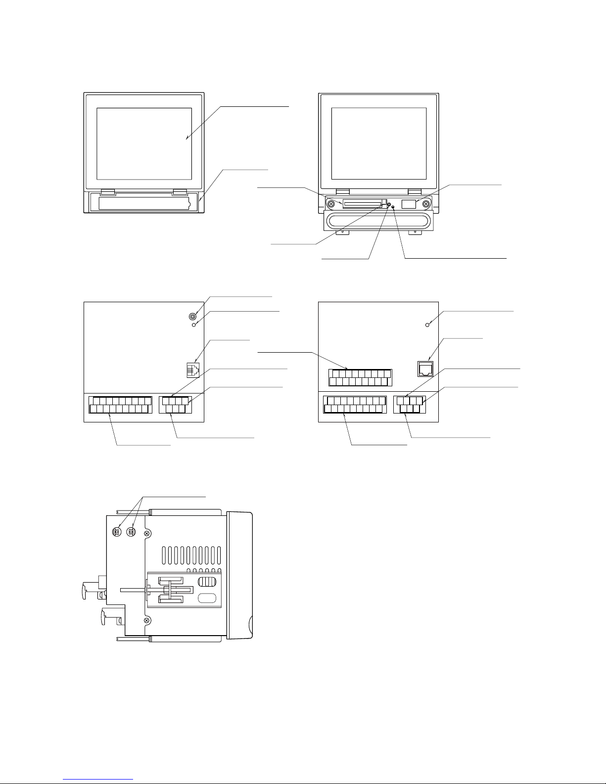
2.2 73VR21x COMPONENT IDENTIFICATIONS
■ FRONT VIEW
• 73VR21x
■ REAR VIEW
• 73VR2102, 73VR2104, 73VR2106
(2) Front Cover
(6) CF Card Access Indicator LED
(7) USB Connector
(3) CF Card Slot
(4) Eject Button
(5) Reset Button
(1) Touch Panel Screen
(13) Trigger Input Terminal
(14) Signal Input
Terminal Block
(14) Signal Input
Terminal Block
(
14
) Signal Input
Terminal Block
(8) Maintenance Jack
(10) LAN Port
(9) Power Indicator LED
(9) Power Indicator LED
(10) LAN Port
(11) Alarm Output Terminal
(12) Power Input Terminal
(13) Trigger Input Terminal
(11) Alarm Output Terminal
(12) Power Input Terminal
1A 1B 1C 3A 3B 3C 5A 5B 5C
2A 2B 2C 4A 4B 4C 6A 6B 6C
1A 1B 1C 3A 3B 3C 5A 5B 5C
2A 2B 2C 4A 4B 4C 6A 6B 6C
FG
ALM+ALM–U
(+)V(+)
TRG+TRG
–
7A 7B 7C 9A 9B 9C
11A11B11C
8A 8B 8C
10A10B10C12A12B12C
(8) Maintenance Jack
■ SIDE VIEW
• 73VR2108, 73VR2110, 73VR2112
• 73VR2108, 73VR2110, 73VR2112
FG
ALM+ALM–U
(+)V(+)
TRG+TRG
–
(1) Touch Panel Screen
Trend chart and other data views and setup views are
displayed.
(2) Front Cover
Access to the CF Card Slot.
(3) CF Card Slot
Insert a CF Card.
(4) Eject Button
Used to retrieve the CF Card.
(5) Reset Button
Used to restart the 73VR21xx.
(6) CF Card Access Indicator LED
Red light turns on during the CF Card is accessed.
(7) USB Connector
Connect an USB flash-memory.
(8) Maintenance Jack
Unused
(9) Power Indicator LED
Light turns on while the power is supplied.
(10) LAN Port
Connects the LAN cable (10BASE-T or 100BASE-TX)
(11) Alarm Output Terminal
(12) Power Input Terminal
(13) Trigger Input Terminal
(14) Signal Input terminal Block
Page 13
13
73VR2102 / 73VR2104 / 73VR2106 / 73VR2108 / 73VR2110 / 73VR2112 USERS MANUAL EM-7395-B Rev.24
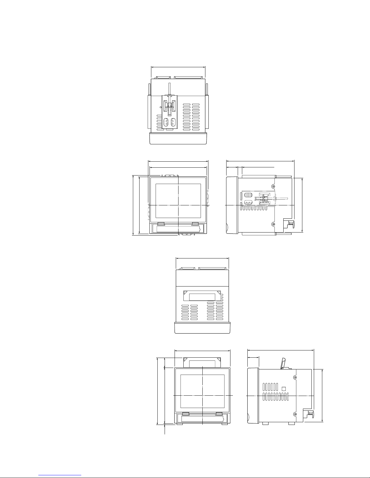
2.3 INSTALLING THE 73VR21x
n EXTERNAL DIMENSIONS unit: mm (inch)
73VR2102, 73VR2104, 73VR2106
• PANEL MOUNT TYPE
144 (5.67)
172 (6.77)
29.5
(1.16)
2 to 26 panel thickness
(.08 to 1.02)
Attach the mounting bracket either on the top/bottom or on the sides.
151.5 (5.96)
144 (5.67)
136.5 (5.37)
151.5 (5.96)
136.5 (5.37)
• DESKTOP TYPE
144 (5.67)
172 (6.77)
29.5
(1.16)
144 (5.67)
136.5 (5.37)
136.5 (5.37)
The handle and rubber feet cannot be detached from desktop type unit.
25
(.98)
173 (6.81)
4
(.16)
Page 14
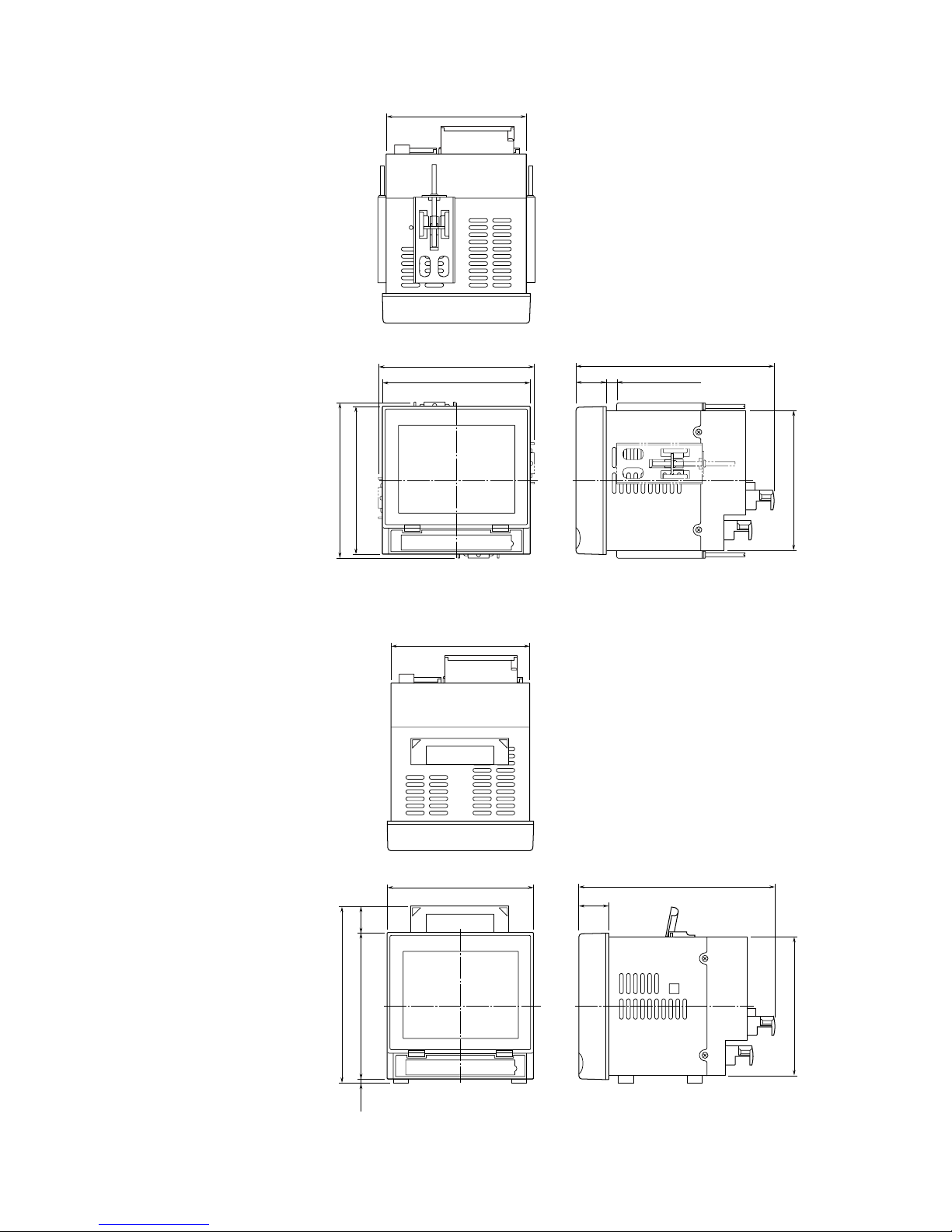
14
73VR2102 / 73VR2104 / 73VR2106 / 73VR2108 / 73VR2110 / 73VR2112 USERS MANUAL EM-7395-B Rev.24
73VR2108, 73VR2110, 73VR2112
• PANEL MOUNT TYPE
Attach the mounting bracket either on the top/bottom or on the sides.
144 (5.67)
151.5 (5.96)
144 (5.67)
151.5 (5.96)
195 (7.68)
29.5
(1.16)
2 to 26 panel thickness
(.08 to 1.02)
136.5 (5.37)
136.5 (5.37)
• DESKTOP TYPE
144 (5.67)
144 (5.67)
195 (7.68)
29.5
(1.16)
136.5 (5.37)
136.5 (5.37)
173 (6.81)
4
(.16)
25
(.98)
The handle and rubber feet cannot be detached from desktop type unit.
Page 15
15
73VR2102 / 73VR2104 / 73VR2106 / 73VR2108 / 73VR2110 / 73VR2112 USERS MANUAL EM-7395-B Rev.24
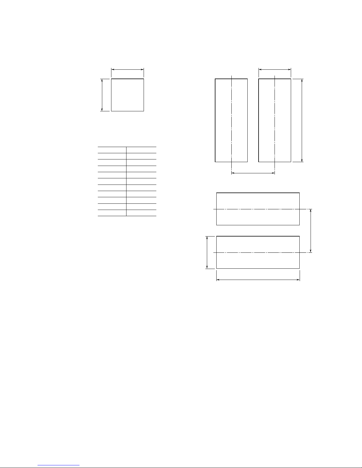
n PANEL CUTOUT unit: mm
Usable panel thickness: 2 – 26 mm (0.08” – 1.02”)
Usable panel material: Steel
137
+2
0
137
+2
0
137
+2
0
n
SINGLE MOUNTING
n
VERTICAL CLUSTERED MOUNTING (max. 3 units)
n HORIZONTAL CLUSTERED MOUNTING
L
+2
0
137
+2
0
175 min
L
+2
0
L (mm)
Number
2
3
4
5
6
7
8
9
10
n
282
426
570
714
858
1002
1146
1290
1434
(114 × n) – 6
+2
0
175 min
Notes
1. Dimensional tolerance ±3% unless otherwise specified.
(±0.3 mm for <10 mm)
2. Desktop type cannot be mounted on a panel surface.
Page 16
16
73VR2102 / 73VR2104 / 73VR2106 / 73VR2108 / 73VR2110 / 73VR2112 USERS MANUAL EM-7395-B Rev.24
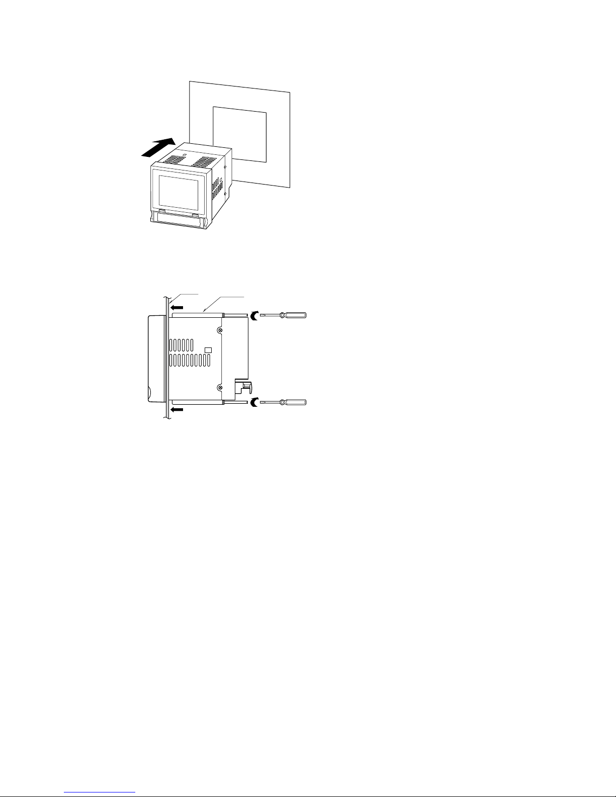
INSTALLATION PROCEDURE
1. Insert the 73VR21x from the front side of the panel.
2. Remove the sheets covering the mounting bracket holes. Fix two mounting brackets either on the sides or on the
top and bottom of the unit. Tighten screws.
Bracket
Panel
CAUTION !
Adequate tightening torque for the screws used to mount the unit onto the panel is between 0.8 and 1.2 N·m. If an
excessive force is applied, the unit’s enclosure may be destroyed, or the panel may be distorted, which would cause
a compromise in the unit’s protection against water or liquid ingress.
Page 17
17
73VR2102 / 73VR2104 / 73VR2106 / 73VR2108 / 73VR2110 / 73VR2112 USERS MANUAL EM-7395-B Rev.24
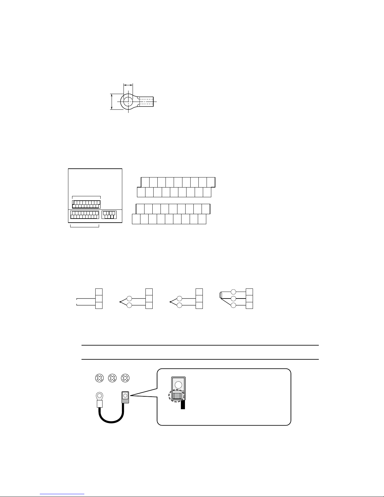
2.4 TERMINAL WIRING
TERMINAL BLOCK
Connection: M3 screw terminal
Screw terminal material: Nickel-plated steel (torque 0.5 N·m)
Applicable wire size: 0.25 to 1.65 mm
2
(AWG 22 to 16)
Recommended manufacturer: Japan Solderless Terminal MFG.Co.Ltd, Nichifu Co.,ltd
6 (.24) max
3.3 (.13) max
mm (inch)
INPUT SIGNAL WIRES
1. Conrm that the power supply is turned off and open the input terminal cover.
2. Connect the wires to the terminal. Remove the CJC sensor(s) from Input 1 and Input 7 terminals when connecting
an RTD to them. If you want to mix thermocouple and RTD inputs, connect a thermocouple to Input 1 and Input
7 terminals.
3. Close the cover.
7A 7B 7C 9A 9B 9C
11A 11B 11C
8A 8B 8C
10A 10B10C 12A 12B 12C
1A 1B 1C 3A 3B 3C 5A 5B 5C
2A 2B 2C 4A 4B 4C 6A 6B 6C
n INPUT TERMINAL ASSIGNMENT
Te rminals 1A, 1B, 1C : Input 1
Te rminals 2A, 2B, 2C : Input 2
Te rminals 3A, 3B, 3C : Input 3
Te rminals 4A, 4B, 4C : Input 4
Te rminals 5A, 5B, 5C : Input 5
Te rminals 6A, 6B, 6C : Input 6
Te rminals 7A, 7B, 7C : Input 7
Te rminals 8A, 8B, 8C : Input 8
Te rminals 9A, 9B, 9C : Input 9
Te rminals 10A, 10B, 10C : Input 10
Te rminals 11A, 11B, 11C : Input 11
Te rminals 12A, 12B, 12C : Input 12
C
B
A
ext. wire
+
–
+
–
C
B
A
C
B
A
ext. wire
–
+
–
+
C
B
A
+
–
A
B
B
n DC INPUT n T/C INPUT
• Upscale / No Burnout
n T/C INPUT
• Downscale Burnout
n RTD INPUT
Input Connection Examples
Input Terminals
Input 1 thr. 6
Input Terminals
Input 7 thr. 12
Notes
Usable number of terminals depends upon the input
type designated by the model number.
Te rminal blocks are separable. The top row one is for
Input 7 through 12, and the bottom row is for Input 1
through 6.
CAUTION !
The CJC sensor must be attached to the terminals 1A and 1C as shown below. For the 73VR2108,
73VR2110 and 73VR2112, connect one also to the terminals 7A and 7C.
1A 1B 1C
CJC Sensor
REAR Side
An RTD is attached on the REAR side of the
CJC sensor.
In order to measure accurate reference junction
temperature, be sure to set the FRONT side of
the sensor visible on top side of the terminal 1C.
FRONT Side
Page 18

18
73VR2102 / 73VR2104 / 73VR2106 / 73VR2108 / 73VR2110 / 73VR2112 USERS MANUAL EM-7395-B Rev.24
ALARM OUTPUT WIRES
1. Conrm that the power supply is turned off and open the alarm output terminal cover.
2. Connect the wires to the terminal.
3. Close the cover.
TRIGGER INPUT WIRES
n ALARM OUTPUT TERMINAL ASSIGNMENT
Alarm Output Terminals
FG
ALM+ALM
–U(+)V(–)
TRG+TRG
–
1. Conrm that the power supply is turned off and open the trigger input terminal cover.
2. Connect the wires to the terminal.
3. Close the cover.
POWER INPUT
n TRIGGER INPUT TERMINAL ASSIGNMENT
Tr igger Input Terminals
FG
ALM+ALM
–U(+)V(–)
TRG+TRG
–
• Power input rating & operational range: Check the power rating for the unit on the specications.
100 – 240V AC rating: 85 – 264V, 47 – 66 Hz, approx. 25VA at 100V, approx. 35VA at 240V
24V DC rating: 24V ±10%, approx. 11W
• Supplying any level of power other than specied above can damage the 73VR21x or the power source.
• The power cables and the signal I/O cables for the 73VR21x must be located separately.
• The main circuit cables (high voltage and high current), the signal I/O cables, and the power cables should not be
bundled together or placed near each other.
1. Conrm that the power supply is turned off and open the power input terminal cover.
2. Connect the wires to the terminal.
3. Close the cover.
n POWER INPUT TERMINAL ASSIGNMENT
Power Input Terminals
FG
ALM+ALM–U
(+)V(–)
TRG+TRG
–
Page 19

19
73VR2102 / 73VR2104 / 73VR2106 / 73VR2108 / 73VR2110 / 73VR2112 USERS MANUAL EM-7395-B Rev.24
2.5 CF CARD
M-System will not guarantee the product’s described performance if a CF Card other than purchased from M-System,
or specied below, is used. CF card can be purchased from M-System. Consult M-System.
1. Manufacturer: Hagiwara Solutions
Model No.: MCF10P-xxxxS (Alternative model: CFI-xxxxDG)
Capacity: 128 MB through 1 GB
2. Manufacturer: Apacer Technology
Model name: CFC III
Model No.: AP-CFxxxxE3ER-ETNDNRK Parts No.: 256 MB ... 81.2A010.1H34C
512 MB ... 81.2B010.1H34C
1 GB ... 81.2E010.1H34C
Model No.: AP-CFxxxxE3ER-ETNDNR Parts No.: 256 MB ... 81.2A010.1H10C
512 MB ... 81.2B010.1H10C
1 GB ... 81.2E010.1H10C
Capacity: 256 MB through 1 GB
The 73VR21x reads the setting le (e.g. storing condition, pen setting) in the CF Card during its startup. If you have
started the 73VR21x without the CF Card inserted in the unit, it reads settings stored in the unit.
The setting in the card is not read in if you inserted it after the unit has been started.
Be sure to have the CF Card inserted before the power supply is turned on.
CAUTION !
• DO NOT turn off the power supply to the 73VR21x or reset it during data recording. The CF Card can be removed
during recording, but observe a specic procedure described in Section “9. DISPLAY VIEWS” of this manual.
• Conrm the sides of the CF Card and the connector position. The side with label is the bottom side.
WARNING ! – Data in the CF Card May be Lost
Data le in the CF Card is reset by the following actions. Data in the le is deleted and overwritten when the card is
reset. We recommend you to keep data backup les in an external device.
• Changing data format in System Conguration
• Changing storing interval in Store Setting
• Enabling/Disabling pens (including Function pens)
• Hot swapping the CF Card
INSERTING THE CF CARD
1. Open the front cover.
2. Insert the CF Card so that its side without label is on the top.
3. Push it in until EJECT button is popped up.
4. Close the front cover.
REMOVING THE CF CARD (DURING RECORDING)
1. According to “10.4 HOT SWAPPING THE CF CARD”, perform the hot swapping.
2. Push EJECT button to extract the CF Card.
REMOVING THE CF CARD (CF CARD IS SWAPPED DURING STOPPING)
1. When the CF card, which differs from the one inserted into 73VR21xx, is
going to inserted, follow the instruction below.
2. If the power is supplied to the 73VR21xx, conrm with the LED behind the
cover that the CF Card is not accessed.
3. According to “10.4 HOT SWAPPING THE CF CARD”, perform the hot swapping the CF card to remove the CF card.
4. Push EJECT button to extract the CF Card.
5. When inserting the CF card, According to “10.4 HOT SWAPPING THE CF CARD”, perform the hot swapping the
CF card to insert the CF card. In this case, the data in the inserted CF card is deleted.
CF Card
TOP
Page 20

20
73VR2102 / 73VR2104 / 73VR2106 / 73VR2108 / 73VR2110 / 73VR2112 USERS MANUAL EM-7395-B Rev.24
REMOVING THE CF CARD (STOPPING, WHEN SAME CF CARD IS SWAPPED)
1. When the CF card, which was inserted into 73VR21xx, is going to inserted, follow the instruction below.
2. If the power is supplied to the 73VR21xx, conrm with the LED behind the cover that the CF Card is not accessed.
3. Push EJECT button to extract the CF Card
4. Special operation is not required when CF card is inserted. In this case, the data in the inserted CF card is not
deleted. (The inserted CF card must not be deleted or edited the le in the card with PC etc.)
2.6 SD CARD
The operation conrmed SD/CF conversion adapter and SD card described below are available for storing on SD
card. The SD/CF conversion adapter, which has SD card incorporated, can be handled as CF card. SD card can be
purchased from M-System (except SD/CF conversion adapter). Consult M-System.
SD/CF conversion adapter: DeLOCK adaptor CF II to SDHC,SDXC,
61796 (operation has been conrmed with the adaptor purchased in the year of
2016.)
62637 (operation has been conrmed with the adaptor purchased in the year of
2018.)
SD card: Hagiwara Solutions NSDA-004GT (discontinued), NSDA-004GL (discontinued),
NSD6-004GH (B21SEI
Note: The use of recommended device prevents loose of data, however correct operating it is not always guaranteed.
WARNING ! – SD card limitations
• SD card memory is 4 GB, however, only 1 GB will be used.
• Storing interval 100 msec. setting is not available. Use the SD card in a storing interval slower than 0.5 sec.
• Do NOT hot swap the CF card every minute on the minute (at 00 second). The data of one cycle may be lost.
• FTP data transfer setting is not available. If FTP data transfer operation starts during storing data on SD card, data
on SD card may be lost.
• When formatting SD card, use a dedicated software “SD Card Formatter”.
“SD Card Formatter” is downloadable at SD Association’s web site.
https://www.sdcard.org
Page 21

21
73VR2102 / 73VR2104 / 73VR2106 / 73VR2108 / 73VR2110 / 73VR2112 USERS MANUAL EM-7395-B Rev.24
3. HARDWARE CONFIGURATIONS
Burnout, Cold junction compensation, Line noise lter and A/D conversion mode are selectable. Analog inputs’ update
cycle is determined by the line noise lter and the A/D conversion mode..
Burnout for T/C and RTD input
Upscale, Downscale or No burnout selectable. Select ‘No Burnout’ to minimize the measuring errors caused by the
sensor/wire resistance and the burnout sensing current.
>>> Refer to Section “5.5.1 PEN SETTING (INPUT)”.
Cold junction compensation (CJC) for T/C input
CJC can be enabled or disabled per each channel.
>>> Refer to Section “5.5.1 PEN SETTING (INPUT)”.
Line noise lter
NMNR ratio to the line frequency and its harmonic contents can be optimized. Select either frequency for the most
effective result.
>>> Refer to Section “5.6 HARDWARE CONFIGURATION”.
A/D conversion mode
Fast, Medium or Slow selectable for all channels.
With Slow setting, data uctuations are minimized with limited sampling time (speed). With Fast setting, sampling time
(speed) can be high through data uctuations increase.
>>> Refer to Section “5.6 HARDWARE CONFIGURATION”.
n ANALOG INPUTS’ UPDATE CYCLE
LINE NOISE FILTER FREQ.
A/D CONVERSION (sec.)
MEDIUM*
1
SLOW FA ST 100 ms RATE
50 Hz 0.39 0.54 0.27
0.09550/60 Hz 0.37 0.50 0.25
60 Hz 0.34 0.46 0.23
Multiplied by two (2) for RTD and potentiometer input.
*1. Standard setting
Page 22
22
73VR2102 / 73VR2104 / 73VR2106 / 73VR2108 / 73VR2110 / 73VR2112 USERS MANUAL EM-7395-B Rev.24
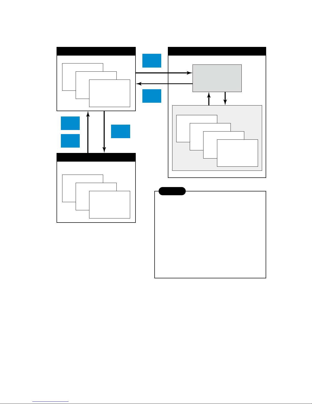
4. 73VR21x VIEWS & BASIC OPERATIONS
Views used in the 73VR21x are grouped in three functions: Data display, Setting and Data retrieval. Groups and views
are related to each other as shown in the gure below.
Pen Setting
Store Setting
Display Setting
System Setting
SETTING VIEWS
SET_MAIN
SETTING
Bargraph
Overview
Trend Graph
DATA DISPLAY
Comment History
Alarm History
Retrieve
Retrieve
Record
Record
Config
Alarm
History
DATA RETRIEVAL
Shows currently recorded data in real time.
Shows past data stored in the CF Card.
Usable even while recording is in progress.
Used to set up the 73VR210x.
1. The setting stored in the CF Card is valid if you have
the card inserted in the 73VR21x when the power
supply to the unit is turned on.
Any setting modification is stored in the card in this
condition.
2. The setting stored in the 73VR21x is valid if you
have no card in the 73VR21x when the power
supply is turned on.
Any setting modification is stored in the unit in this
condition.
You can copy the setting stored in the unit to a card
using the Builder Software or the reading/writing
operation of the unit via USB Flash Memory.
CAUTION
Page 23
23
73VR2102 / 73VR2104 / 73VR2106 / 73VR2108 / 73VR2110 / 73VR2112 USERS MANUAL EM-7395-B Rev.24
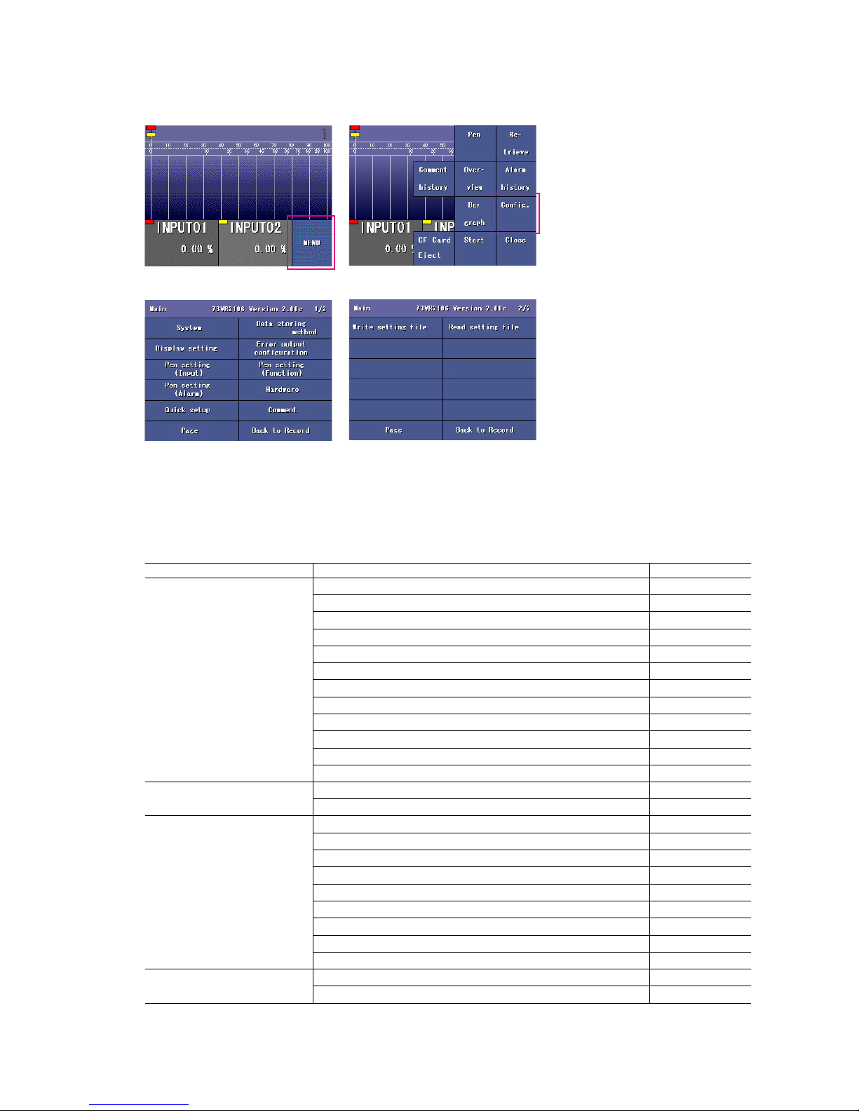
5. SETTING UP THE 73VR21x
Touching Menu key on one of the display views (Trend, Overview and Bargraph) opens selectable menu items on the
right half of the screen. Touch Cong key to open Main view listing the name of detailed setting windows.
Figure: Menu key. Figure: Cong key.
Figure: Main view 1. Figure: Main view 2.
In order to enable new setting, touch Back to Record key and go back to the previously displayed recording view
(Trend, Overview and Bargraph).
n MAIN MENU & SUB MENU LIST
MODIFY : Y = Can be modied during recording, N = Not)
MAIN MENU SUB MENU MODIFY
System Operating mode N
Temperature unit N
Start mode N
Data storing form N
Data overwrite N
Screen saver Y
Touch panel beep Y
Date and time N
Password N
IP address N
Subnet mask N
Default gateway N
Data storing method Storing interval N
Storing setting N
Display setting Chart speed N
Graph direction Y
Digital display type Y
Digital display Y
Data le used volume Y
Display pen number Y
Display pen number (Overview) Y
Auto pen switching Y
Chart color Y
Error output Enable / Disable N
Output ch. N
Page 24

24
73VR2102 / 73VR2104 / 73VR2106 / 73VR2108 / 73VR2110 / 73VR2112 USERS MANUAL EM-7395-B Rev.24
MAIN MENU SUB MENU MODIFY
Pen setting (Input) Enable / Disable N
Ta g N
Unit N
Color Y
Line thickness Y
Analog Decimal place Y
Square root N
Overview color Y
Analog type N
Input range N
Engineering range N
Plot position Y
Scale shift Y
Normal / Log (Exp. scale, Log. plot position) N
CJC (Cold Junction Compensation) SW N
Burnout type Y
Discrete OFF description N
ON description N
Pen setting (Function) Enable / Disable N
Ta g N
Unit N
Color N
Line thickness N
Function N
Equation N
Analog Decimal place Y
Overview color Y
Plot position Y
Scale shift Y
Normal / Log (Exp. scale, Log. plot position) N
Discrete OFF description N
ON description N
Pen setting (Alarm) Analog Limit 1...4 Y
Deadband 1...4 Y
Normal zone Y
Zone color 0...4 Y
Alarm output Y
Relay Y
Up message Y
Down message Y
Discrete OFF output Y
ON output Y
Delay Y
Normal state Y
OFF color Y
ON color Y
OFF Message Output Y
ON Message Output Y
OFF Message Y
ON Message Y
Hardware AD conversion mode N
Line noise lter N
Zero/span adjustment N
Quick setup Group name Y
Group color Y
Comment Y
Comment Comment direct input Y
Group name Y
Group color Y
Comment (Group 7 comment can be modied during recording) Y
Write setting le N
Read setting le N
Page 25
25
73VR2102 / 73VR2104 / 73VR2106 / 73VR2108 / 73VR2110 / 73VR2112 USERS MANUAL EM-7395-B Rev.24
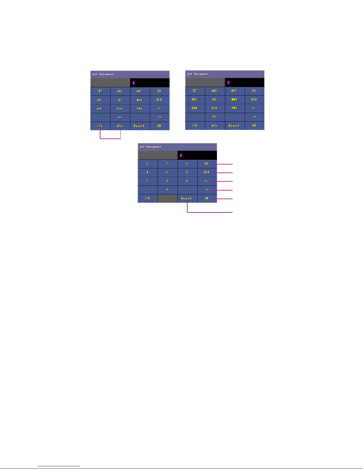
n TIPS FOR KEY OPERATIONS
Alphanumeric Keypads
When you need to enter alphabets and numbers during a setting process, the alphanumeric keypads consisting three
pages are used: Small letters, Capital letters and Numbers as shown below.
Figure: Small letters. Figure: Capital letters.
Back space
Clear
Backward
Forward
OK
Cancel
Switching keypads
Figure: Numbers.
For example, the key showing ‘abc’ is used to enter characters ‘a,’ ‘b,’ or ‘c.’ ‘a’ is entered by touching the key once, ‘b’
for twice, and ‘c’ for three times. Other letters can be selected in the same manner. When you need to enter the same
character or another character on the same key in series, move the cursor before choosing the second character.
OK and Cancel Keys
When you are satised with changes you applied, touch OK to conrm the setting and move to the next window. If
you do not want to apply the changes, touch Cancel key.
Page, Next and Previous Keys
When more than one page exist for one menu item, use Page key to switch from one page to another.
Next and Previous keys are used to move between different channels for the same setting item.
Record Key
Important !
In order to apply new setting, touch Record key to save and return to one of the Display views (Trend, Overview or
Bargraph).
Page 26
26
73VR2102 / 73VR2104 / 73VR2106 / 73VR2108 / 73VR2110 / 73VR2112 USERS MANUAL EM-7395-B Rev.24
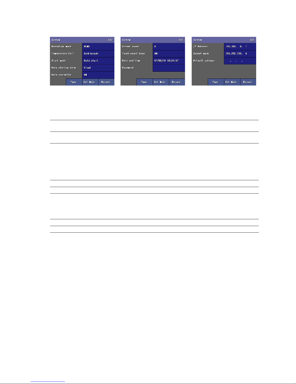
5.1 SYSTEM SETTING
The System setting menu consists of three views as shown below.
Touch Page key to switch between pages.
5.1.1 OPERATING MODE
Touching the current selection of the Operating mode shows selectable options at the bottom of the screen. Choose
among the following options.
DEMO Demonstration mode You can run the 73VR21x program without actual signal input for
learning, evaluation and demonstration when you choose DEMO.
Normal Running mode Choose this option when you connect actual input signals to the
73VR21x.
5.1.2 TEMPERATURE UNIT
Touching the current selection of the Temperature Unit shows selectable options at the bottom of the screen. Choose
among the following options.
When 100 msec. storing rate (interval) has been or to be selected, temperature unit setting is invalid since temperature
input modules are usable only for 500 msec. or longer intervals.
Centigrade Centigrade (Celsius)
Fahrenheit Fahrenheit
5.1.3 START MODE
Touching the current selection of the Start Mode shows selectable options at the bottom of the screen. Choose among
the following options.
Cold Start At a restart, the 73VR21x stands by showing the initial view.
Hot Start At a restart, the 73VR21x automatically starts recording.
Page 27

27
73VR2102 / 73VR2104 / 73VR2106 / 73VR2108 / 73VR2110 / 73VR2112 USERS MANUAL EM-7395-B Rev.24
5.1.4 DATA STORING FORM
Touching the current selection of the Data Storing Form shows selectable options at the bottom of the screen. Choose
among the following options.
Float Floating point 1 data size: 4 bytes
Decimal fraction: max. 4 decimal places (effective number of digits: 6 or 7)
Float is to be selected when you need to store data including decimal fractions. The
4-byte-long data is better in data precision but the total storable time in the CF Card
becomes shorter compared from Short Int.
Short int Short integer Integer data multiplied by 10. The 2-byte-long data is not as precise (one decimal
place) as Float type is, but the total storable time in the CF Card is longer.
WHICH FORM TO CHOOSE? -- EXAMPLE
If you have selected Short integer, and when an input range 1 – 5V is converted in an engineering unit range of 0 –
10, the actual converted values are: 0 at 1V input, 0.25 at 1.1V. In this case, the 73VR21x can store only one decimal
place, and ‘0.25’ is saved only as ‘0.2.’ Likewise, the input 1.15V is converted into 0.275 in the engineering unit range,
but is saved also as ‘0.2.’ 1.1V and 1.15V inputs make no difference in the short integer form.
Choose Float if you want to make difference between 1.1V and 1.15V.
WARNING !
When the data storing form setting is changed, new data stored in the same data le overwrite previously stored data.
5.1.5 DATA OVERWRITE
You can specify if you want to stop recording or continue recording by overwriting the oldest data when the CF card
capacity is full. Detailed explanations on the data le is given in Section “10.1 73VR21x FILES”.
OFF Recording is stopped.
ON Recording continues by overwriting the oldest data.
5.1.6 SCREEN SAVER
The LCD display’s backlight can be turned off when the screen is untouched for a specic time period.
Touching the current selection of the Screen saver replaces the screen with a numeric keypad. The setting can be
modied even while recording is in progress.
Enter a desired time in minutes to initiate the screen saver.
Screen saver time setting Selectable range: 0 to 99 (minutes)
The screensaver function is deactivated with the time set to zero (0).
Touching the screen cancels the screen saver mode. The screen saver is automatically cancelled when an alarm is
output.
5.1.7 TOUCH PANEL BEEP
You can specify if you want a beep sound or not whenever you touch the screen.
Touching the current selection of the Touch panel beep shows selectable options at the bottom of the screen. The
setting can be modied even while recording is in progress.
OFF Beep sound is off.
ON Beep sound is on.
Page 28

28
73VR2102 / 73VR2104 / 73VR2106 / 73VR2108 / 73VR2110 / 73VR2112 USERS MANUAL EM-7395-B Rev.24
5.1.8 DATE AND TIME
Date / time is indicated in the format: YY / MM / DD HH : MM : SS.
Touching the current time index replaces the screen with a numeric keypad. Enter a correct time and touch OK.
CAUTION !
If incorrect date is entered, OK button turns grey and becomes disabled.
CAUTION !
After the clock has been rewound (e.g. from 10:02:34 to 10:00:00), a part of the data in Data le, Comment history le
and Alarm history le will be deleted in certain conditions as explained in the following. They are not deleted when
the clock has been forwarded.
1. When you touch Start button, a warning dialog box will appear if the clock shows the time earlier than the last
data’s time index in the data les. When you touch OK, the data will be deleted. If you touch Cancel, no data will
be deleted but recording is stopped.
With the remote trigger, event recording or time specied storing mode, data will be deleted not at the moment of
Start, but at the moment of the trigger (or the specied time).
2. With Hot Start setting, data will be deleted without warning if the clock shows the time earlier than the last data’s
time index in the data les when the data recording has been started automatically.
3. When the recorder is started remotely by the 73VR21BLD or MSR128, data will be deleted without warning if the
clock shows the time earlier than the last data’s time index in the data les.
5.1.9 PASSWORD
Password setting prevents unauthorized access to data displays and changes in the setting. When you have set a
password and returns to one of the Display views, the password will be requested every time you touch a control key
on the screen.
Once the password lock is released, you can access control keys and move to other views including Cong.
Password Max. 6 alphanumeric characters
CAUTION !
The password lock function is valid only on the Display view (Trend, Overview or Bargraph). If another view is left open
in unlocked state, anyone can change its setting.
If you forgot your password, please contact M-System.
The following functions are available without needing a password:
• Switching Pages within the same function view.
• Updating digital displays
•Zooming in a digital display
5.1.10 IP ADDRESS
In order to connect the 73VR21x to a PC via Ethernet when using the 73VR21BLD (Builder) or the 73VRWV (Data
Viewer), set an appropriate IP address.
Touching the current selection of the IP address replaces the screen with a numeric keypad. Enter a desired IP address on the keypad and touch OK.
IP address Factory default setting: 192.168.0.1
CAUTION !
In order to apply new IP address setting, the 73VR21x must be restarted. Be sure to return to one of the Display views
to save the new setting. All new setting will be lost otherwise.
Consult your network administrator for IP address.
Page 29

29
73VR2102 / 73VR2104 / 73VR2106 / 73VR2108 / 73VR2110 / 73VR2112 USERS MANUAL EM-7395-B Rev.24
5.1.11 SUBNET MASK
Touching the current selection of the subnet mask replaces the screen with a numeric keypad. Enter a desired value
on the keypad and touch OK.
Subnet mask Factory default setting: 255.255.255.0
CAUTION !
In order to apply new subnet mask setting, the 73VR21x must be restarted. Be sure to return to one of the Display
views to save the new setting. All new setting will be lost otherwise.
Consult your network administrator for subnet mask.
5.1.12 DEFAULT GATEWAY
Touching the current selection of the default gateway replaces the screen with a numeric keypad. Enter a desired
value on the keypad and touch OK.
Default gateway Factory default setting: None
CAUTION !
In order to apply new default gateway setting, the 73VR21x must be restarted. Be sure to return to one of the Display
views to save the new setting. All new setting will be lost otherwise.
Consult your network administrator for default gateway.
5.1.13 LINGER TIME
TCP Socket is closed after no communication is detected for a preset Linger Time. This setting is used when connecting to a host PC via Modbus/TCP.
Touching the current selection of the linger time replaces the screen with a numeric keypad. Enter a desired value
on the keypad and touch OK.
Linger time 0.0 to 3000.0 seconds (100 msec. increments)
Page 30

30
73VR2102 / 73VR2104 / 73VR2106 / 73VR2108 / 73VR2110 / 73VR2112 USERS MANUAL EM-7395-B Rev.24
5.2 DATA STORING METHOD
The initial view for the Data storing method setting is as shown below.
5.2.1 STORING INTERVAL
The data is stored in time intervals preset as the Storing interval.
Touching the current selection of the Storing interval shows selectable options at the bottom of the screen. Choose
among the following options. For the F value calculation, choose 500 milliseconds:
100msec 100 milliseconds
500msec 500 milliseconds
1sec 1 second
2sec 2 seconds
5sec 5 seconds
10sec 10 seconds
1min 1 minute
10min 10 minutes
Total recording time in a CF Card depends upon the storing interval selection. Selecting greater storing interval allows
longer recording time, though the data are more thinned, which may jeopardize the data accuracy.
CAUTION !
When the storing interval setting is changed, previously stored data are overwritten with new data.
Consider analog inputs’ update cycle when determining the storing interval.
n ANALOG INPUTS’ UPDATE CYCLE
LINE NOISE FILTER FREQ.
A/D CONVERSION (sec.)
MEDIUM*
1
SLOW FAS T 100 ms RATE
50 Hz 0.39 0.54 0.27
0.095
50/60 Hz*
1
0.37 0.50 0.25
60 Hz 0.34 0.46 0.23
Multiplied by two (2) for RTD and potentiometer input.
*1. Standard setting
Page 31

31
73VR2102 / 73VR2104 / 73VR2106 / 73VR2108 / 73VR2110 / 73VR2112 USERS MANUAL EM-7395-B Rev.24
5.2.2 STORING SETTING
Five storing methods are selectable.
Touching the current selection of the Storing interval shows selectable options at the bottom of the screen. Choose
among the following options:
No storing No recording Data is plotted on the chart or displayed on the digital meter or bargraph,
but no data is stored in the CF Card.
Normal Normal storing mode Recording is manually initiated and stopped. Data is continuously stored
while the recording is on.
Remote trigger Remote trigger recording
mode
Data is automatically recorded while the external trigger condition (analog
or discrete input) is true. (See “5.2.3 REMOTE TRIGGER RECORDING”)
Event recording Event recording mode The 73VR21x detects an external event by trigger signal, and stores pre-
set number of samples (max. 1200 respectively) before and after the moment of event. (See “5.2.4 EVENT RECORDING”)
Time specied Store at dened time mode Recording is automatically initiated and stopped at predened time. (See
“5.2.5 STORE AT A DEFINED TIME MODE”)
Page 32

32
73VR2102 / 73VR2104 / 73VR2106 / 73VR2108 / 73VR2110 / 73VR2112 USERS MANUAL EM-7395-B Rev.24
5.2.3 REMOTE TRIGGER RECORDING
In the remote trigger recording mode, data is automatically stored while the external trigger condition (analog or discrete input) is true.
With an analog trigger, the signal are continuously compared with a preset threshold, and the 73VR21x starts and
stops recording when it is in a pre-determined condition (higher or lower than the threshold).
With a discrete trigger, the signal logic state is continuously monitored, and the 73VR21x starts and stops recording
when it is turned to a pre-determined state (ON or OFF).
n Trigger Conditions for Analog
Value > Threshold Data is stored while the trigger input signal value is higher than the threshold setpoint.
Value < Threshold Data is stored while the trigger input signal value is lower than the threshold setpoint.
Value ≥ Threshold Data is stored while the trigger input signal value is equal to or higher than the threshold
setpoint.
Value ≤ Threshold Data is stored while the trigger input signal value is equal to or lower than the threshold
setpoint.
n Trigger Conditions for Discrete
ON Data is stored while the trigger input signal logic is ON.
OFF Data is stored while the trigger input signal logic is OFF.
CAUTION !
If you touch Record button while the trigger condition is true, no recording starts until it turns true for a next time.
HOW TO SET THE REMOTE TRIGGER RECORDING
1. Storing setting: Select Remote trigger as explained in “5.2.2 STORING SETTING”. Choosing the Remote trigger
on the Data storing method view changes the subsequent menu items to those suitable for the remote trigger
recording mode.
2. Discrete / Analog: Choose a type of trigger signal.
Discrete Contact signal trigger A discrete signal triggers recording.
Analog Analog signal trigger An analog signal triggers recording.
3. Threshold: For analog signals, set a threshold in an engineering unit value.
Threshold Engineering unit value. Max. 6 digits including decimal point and minus (–) sign. ‘e’ is used
to set an exponential value.
‘e’ can be used to input an exponential value such as ‘1e9.’ Entering ‘e’ in any other way (e.g. ‘1ee’) will not be recognized as a numeral.
4. Condition: Choose among the abovementioned options.
Page 33

33
73VR2102 / 73VR2104 / 73VR2106 / 73VR2108 / 73VR2110 / 73VR2112 USERS MANUAL EM-7395-B Rev.24
5. Pen number: Choose a pen to be designated as trigger. Touching the current selection of Pen number opens the
Storing pen select view which listing all available (meaning the enabled pens) tag names.
Function key
Switches the window to pens assigned to
the operation functions.
This key is replaced with Input key while
the window shows Function tag selections.
5.2.4 EVENT RECORDING
In the event recording mode, the 73VR21x detects an external event by trigger signal, and stores preset number of
samples (max. 1200 respectively) before and after the moment of event.
With an analog trigger, the trigger signal is continuously compared with a preset threshold, and the 73VR21x initiates
recording when it is in a pre-determined condition (higher or lower than the threshold).
With a discrete trigger, the signal logic state is continuously monitored, and the 73VR21x initiates recording when it is
turned to a pre-determined state (ON or OFF).
n Trigger Conditions for Analog
Value > Threshold Data recording is initiated when the trigger input signal value goes above the threshold
setpoint.
Value < Threshold Data recording is initiated when the trigger input signal value goes below the threshold
setpoint.
Value ≥ Threshold Data recording is initiated when the trigger input signal values is equal to or goes above the
threshold setpoint.
Value ≤ Threshold Data recording is initiated when the trigger input signal values is equal to or goes below the
threshold setpoint.
n Trigger Conditions for Discrete
Up Rising pulse edge Data recording is initiated at a rising edge of the trigger input pulse.
Down Sinking pulse edge Data recording is initiated at a sinking edge of the trigger input pulse.
CAUTION !
If you touch Record button while the trigger condition is true, no recording starts until it turns true for a next time.
Page 34

34
73VR2102 / 73VR2104 / 73VR2106 / 73VR2108 / 73VR2110 / 73VR2112 USERS MANUAL EM-7395-B Rev.24
HOW TO SET THE EVENT RECORDING
1. Storing setting: Select Event recording as explained in “5.2.2 STORING SETTING”. Choosing the Event recording
on the Data storing method view changes the subsequent menu items to those suitable for the event recording
mode.
2. Discrete / Analog: Choose a type of trigger signal.
Discrete Contact signal trigger A discrete signal triggers recording.
Analog Analog signal trigger An analog signal triggers recording.
3. Threshold: For analog signals, set a threshold in an engineering unit value.
Threshold Engineering unit value. Max. 6 digits including decimal point and minus (–) sign. ‘e’ is used
to set an exponential value.
‘e’ can be used to input an exponential value such as ‘1e9.’ Entering ‘e’ in any other way (e.g. ‘1ee’) will not be recognized as a numeral.
4. Condition: Choose among the aforementioned options.
5. Pen number: Choose a pen to be designated as trigger. Touching the current selection of Pen number opens the
Storing tag select view (See “5.2.3 REMOTE TRIGGER RECORDING”) which listing all available (meaning the
enabled pens) tag names.
6. Pretrigger / Posttrigger: Specify numbers of samples to be stored before (Pretrigger) and after (Posttrigger) the
event respectively.
Pretrigger Number of pretrigger samples Max. 1200 samples. Pretrigger recording is NOT applicable with
the storing intervals set to 2 seconds or longer.
Posttrigger Number of posttrigger samples Max. 1200 samples.
5.2.5 STORE AT A DEFINED TIME MODE
In the Store-at-a-Dened Time mode, recording is automatically initiated and stopped at a predened time.
Choose either ‘One Time Only’ or ‘Every Day’ under Condition option.
One Time Only Data is stored once at a predened time. Specify Year-Month-Day and Hour-Min-Sec. to start the
recording and the time duration.
Every Day The 73VR21x runs recording once per day at a predened time. Specify Hour-Min-Sec. to start the
recording and the time duration.
CAUTION !
If you touch Record button while in the specied time, no recording starts until a next specied time.
Page 35

35
73VR2102 / 73VR2104 / 73VR2106 / 73VR2108 / 73VR2110 / 73VR2112 USERS MANUAL EM-7395-B Rev.24
HOW TO SET THE STORE-AT-A-DEFINED-TIME MODE
1. Storing setting: Select Time Specied as explained in “5.2.2 STORING SETTING”. Choosing the Time Specied
recording on the Data storing method view changes the subsequent menu items to those suitable for the storing
mode.
2. Touching the current selection opens a numeric keypad to enter a new setting. Specify when you want to start
recording (Datetime) and the time duration (Time). With Every day setting, ‘Date’ is not indicated.
Datetime or time Recording started at Specify YY/MM/DD HH:MM:SS.
Time For Specify HH:MM between 00:00 and 23:59.
5.3 DISPLAY SETTING
The Display setting view is available with the following menu items:
5.3.1 CHART SPEED
Touching the current selection of the Chart speed shows selectable options at the bottom of the screen.
Choose among the options in the table below. The numbers show how many pixels are used for one sample data.
For example, if you choose ‘4,’ one sample is plotted 4 pixels further than the previous one, and two sample points
are connected to create a trend graph.
Plotting already on the screen disappears when the chart speed is changed, except when the new setting is 1 or 4.
The chart speed options may be limited when certain storing intervals are selected. Refer to the table below.
CHART SPEED
STORING INTERVAL
4 1 1/5 1/32 1/160 1/480 1/960
100 msec. Ye s Ye s Ye s Ye s No No No
≥500 msec. Ye s Ye s Ye s Ye s Ye s Ye s Ye s
Page 36

36
73VR2102 / 73VR2104 / 73VR2106 / 73VR2108 / 73VR2110 / 73VR2112 USERS MANUAL EM-7395-B Rev.24
The following tables indicates actual time spans expressed on the chart depending upon different storing intervals.
n Storing Interval 100 msec.
CHART TYPE
CHART SPEED
Perpendicular
with digital display
Perpendicular
without digital display
Horizontal
4 2.7 seconds 4.7 seconds 6.7 seconds
1 11 seconds 19 seconds 27 seconds
1/5 55 seconds 1 min., 35 sec. 2 min., 15 sec.
1/32 5 min., 52 sec. 10 min., 8 sec. 14 min., 24 sec.
n Storing Interval 500 msec. or longer
CHART TYPE
CHART SPEED
Perpendicular
with digital display
Perpendicular
without digital display
Horizontal
4 13.5 seconds 23.5 seconds 33.5 seconds
1 55 seconds 1 min., 35 sec. 2 min., 15 sec.
1/5 4 min., 35 sec. 7 min. 52 sec. 11 min., 15 sec.
1/32 29 min., 20 sec. 50 min., 40 sec. 1 hour, 12 min.
1/160 2 hours, 26 min., 40 sec. 4 hours, 13 min., 20 sec. 6 hours
1/480 7 hours, 20 min. 12 hours, 40 min. 18 hours
1/960 14 hours, 40 min. 1 day, 1 hour, 20 min. 1 day, 12 hours
5.3.2 GRAPH DIRECTION
You can specify if you want to show the chart in the perpendicular direction or the horizontal direction.
Touching the current selection of the Graph direction shows selectable options at the bottom of the screen. The setting
can be modied even while recording is in progress. Choose among the following options:
Perpendicular Perpendicular direction
Horizontal Horizontal direction
5.3.3 DIGITAL DISPLAY TYPE
Touching the current selection of the Digital display type shows selectable options at the bottom of the screen to specify
either to show only the tag name or the value, or both. Choose among the following options:
Tag + Value The momentary value and the tag name of the data displayed on the screen.
Ta g
The tag name of the data displayed on the screen.
Value
The momentary value of the data displayed on the screen.
Page 37

37
73VR2102 / 73VR2104 / 73VR2106 / 73VR2108 / 73VR2110 / 73VR2112 USERS MANUAL EM-7395-B Rev.24
5.3.4 DIGITAL DISPLAY
Touching the current selection of the Digital Display shows selectable options at the bottom of the screen to show or
hide the digital display on the data display view. This option can be changed while recording.
Auto hide Digital display is automatically hidden in 30 seconds after it appears on the screen. Touch
the area of the display to call it up.
Continuous Digital display remains on the screen.
5.3.5 DATA FILE USED VOLUME SETTING
The Overview and the Bargraph view can show a bargraph how much volume of the data le has been used.
The data le is automatically created when the 73VR21x has started up. 0% is shown when there is no data in the
le. Used-up rate is shown in the percentage of the total volume. This option can be changed while recording. For
detailed information refer to Section “9.2 OVERVIEW”.
Not shown Data le used volume bargraph is not shown.
Show Data le used volume bargraph is shown.
Trend, perpendicular. Trend, horizontal. Overview.
5.3.6 DISPLAY PEN NUMBER
You can specify the number of pens to show on the screen in Trend View and Bargraph View.
Touching the current selection of the Display Pen Number shows selectable options at the bottom of the screen. The
setting can be modied even while recording is in progress. Choose among the following options:
2 pens 4 pens 6 pens 8 pens
Page 38

38
73VR2102 / 73VR2104 / 73VR2106 / 73VR2108 / 73VR2110 / 73VR2112 USERS MANUAL EM-7395-B Rev.24
5.3.7 DISPLAY PEN NUMBER (OV)
You can specify the number of pens to show on the screen in Overview.
Touching the current selection of the Display Pen Number shows selectable options at the bottom of the screen. The
setting can be modied even while recording is in progress. Choose among the following options:
2 pens 4 pens 6 pens
8 pens 16 pens
5.3.8 AUTO PEN SWITCHING
You can automatically switch the pens on the enlarged digital display on the screen.
Enable Once the enlarged digital display is activated on the screen, pens are automatically
switched from one to another.
Disable Digital display remains on the same pen when the enlarged digital display is activated.
5.3.9 CHART COLOR
You can specify different types of chart colors.
Touching the current selection of the Chart Color shows selectable options at the bottom of the screen. The setting
can be modied even while recording is in progress. Choose among the following options:
Gradation 1 Gradation 2
Plain (Light) Plain (Dark) Plain (White)
Page 39

39
73VR2102 / 73VR2104 / 73VR2106 / 73VR2108 / 73VR2110 / 73VR2112 USERS MANUAL EM-7395-B Rev.24
5.4 ERROR OUTPUT
With the error output setting is enabled, the 73VR21x outputs an alarm contact at the alarm output terminals when an
internal bus error continues for longer than 1 minute.
If signal alarm outputs are enabled, the output terminals turn ON and OFF by OR logic.
1. Choose Enable or Disable. When Enable is selected, the following selection appears.
2. Contact logic: Specify whether you want to open (OFF) or close (ON) the contact at alarm.
CAUTION !
• The error output setting is enabled when Record key is pressed.
• An alarm is output while the recorder is stopped, because the internal bus communication is stopped.
• No alarm is output while the zero/span calibration is performed.
5.5 PEN SETTING
Three pen setting keys are on the main menu: Pen setting (Input), Pen setting (Function) and Pen setting (Alarm).
Touching one of these three keys opens up Pen selector as shown below:
Pen setting, example of the 73VR2112
Table. Terminal ID v.s. input number, 73VR2102.
TERMINAL ID INPUT NUMBER
1A, 1B, IC Input 1
2A, 2B, 2C Input 2
TRIG +, TRIG – Input 3
Table. Terminal ID v.s. input number, 73VR2104.
TERMINAL ID INPUT NUMBER
1A, 1B, IC Input 1
2A, 2B, 2C Input 2
3A, 3B, 3C Input 3
4A, 4B, 4C Input 4
TRIG+, TRIG– Input 5
Table. Terminal ID v.s. input number, 73VR2106.
TERMINAL ID INPUT NUMBER
1A, 1B, IC Input 1
2A, 2B, 2C Input 2
3A, 3B, 3C Input 3
4A, 4B, 4C Input 4
5A, 5B, 5C Input 5
6A, 6B, 6C Input 6
TRIG +, TRIG – Input 7
Table. Terminal ID v.s. input number, 73VR2108.
TERMINAL ID INPUT NUMBER
1A, 1B, IC Input 1
2A, 2B, 2C Input 2
3A, 3B, 3C Input 3
4A, 4B, 4C Input 4
5A, 5B, 5C Input 5
6A, 6B, 6C Input 6
7A, 7B, 7C Input 7
8A, 8B, 8C Input 8
TRIG +, TRIG – Input 9
Table. Terminal ID v.s. input number, 73VR2110.
TERMINAL ID INPUT NUMBER
1A, 1B, IC Input 1
2A, 2B, 2C Input 2
3A, 3B, 3C Input 3
4A, 4B, 4C Input 4
5A, 5B, 5C Input 5
6A, 6B, 6C Input 6
7A, 7B, 7C Input 7
8A, 8B, 8C Input 8
9A, 9B, 9C Input 9
10A, 10B, 10C Input 10
TRIG +, TRIG – Input 11
Table. Terminal ID v.s. input number, 73VR2112.
TERMINAL ID INPUT NUMBER
1A, 1B, IC Input 1
2A, 2B, 2C Input 2
3A, 3B, 3C Input 3
4A, 4B, 4C Input 4
5A, 5B, 5C Input 5
6A, 6B, 6C Input 6
7A, 7B, 7C Input 7
8A, 8B, 8C Input 8
9A, 9B, 9C Input 9
10A, 10B, 10C Input 10
11A, 11B, 11C Input 11
12A, 12B, 12C Input 12
TRIG +, TRIG – Input 13
Page 40

40
73VR2102 / 73VR2104 / 73VR2106 / 73VR2108 / 73VR2110 / 73VR2112 USERS MANUAL EM-7395-B Rev.24
5.5.1 PEN SETTING (INPUT)
Touching Pen setting (Input) and choosing one of the pens opens the Pen setting (Input) view for the selected.
Pen setting (Input) views have ve pages as shown below:
n ANALOG SETTING
Enable / Disable
Enable / Disable the recording. The pen’s input data is stored when this selection is set to Enable.
Tag name
Touching the current selection of the Tag name opens an alphanumeric keypad.
Tag name Max. 8 characters
Unit
Touching the current selection of the Unit opens an alphanumeric keypad.
Unit Max. 4 characters
Page 41

41
73VR2102 / 73VR2104 / 73VR2106 / 73VR2108 / 73VR2110 / 73VR2112 USERS MANUAL EM-7395-B Rev.24
Color
Touching the current selection of the Color opens a color palette. Choose a desired color from the palette.
Line thickness
This setting is selectable even during recording.
Normal Normal line
Thick Thick line
Decimal place
Decimal places for the digital indicator can be specied. This setting is selectable even during recording.
3 3 decimal places
2 2 decimal places
1 1 decimal place
0 No decimal point
Plot range with decimal place on the scale
Plot range in an engineering unit can be indicated on the scale in Trend and Bargraph views. For example, when the
lower range is set to 0, and the upper range is set to 1000, the scale shows 10 divisions (0, 100, 200, ... 900, 1000).
How many decimal places are to be shown depends upon the ‘Decimal place’setting. For example, when ‘2’ decimals
are selected, the scale shows two decimal places.
For thermocouple and RTD input, only ‘0’ or ‘1’ is selectable.
Square Root
Input data is square-root-extracted when this setting is enabled.
Overview Color
This option can be changed while recording.
Specify the bargraph color for the pen in the Overview. Use the color palette.
If you have specied alarm-specic colors in Pen (Alarm) Setting, these colors are applied instead of Overview Color.
Analog type and Input range
With 100 msec. storing intervals, only voltage input ranges are selectable.
Selectable signal types and input ranges are as shown in the table in the next page. For DC input, choose the upper
and lower range values (0% and 100%) within the measurable range. For temperature input, the input range is equal
to the measurable range, thus xed.
Input range Max. 6 digits including a decimal point and minus sign
Page 42

42
73VR2102 / 73VR2104 / 73VR2106 / 73VR2108 / 73VR2110 / 73VR2112 USERS MANUAL EM-7395-B Rev.24
Table. Analog types
I/O TYPE SELECTIONS INPUT RANGE USABLE RANGE
DC input -12 to 12 V ±12V
—
-6 to 6 V ±6V
-3 to3 V ±3V
-1000 to1000 mV ±1000mV
-500 to500 mV ±500mV
-250 to250 mV ±250mV
-125 to125 mV ±125mV
-60 to60 mV ±60mV
T/C input °C °F
(PR)
Same as the usable
range
0 –1770 32 –3218
K (CA) -270 –1370 -454 –2498
E (CRC) -270 –1000 -454 –1832
J (IC) -210 –1200 -346 –2192
T (CC) -270 –400 -454 –752
B (RH) 100 –1820 212 –3308
R -50 –1760 -58 –3200
S -50 –1760 -58 –3200
C (WRe 5-26) 0 –2320 32 –4208
N -270 –1300 -454 –2372
U -200 –600 -328 –1112
L -200 –900 -328 –1652
P (Platinel II) 0 –1395 32 –2543
RTD input JPt 100 (JIS ’89)
Same as the usable
range
-200 – 510 -328 – 950
Pt 100 (JIS ’89) -200 – 660 -328 – 1220
Pt 100 (JIS ’97, IEC) -200 – 850 -328 – 1562
Pt 50 Ω (JIS ’81) -200 – 649 -328 – 1200
Ni 508.4 Ω -50 – 280 -58 – 536
Ni 100 -80 – 260 -112 – 500
Ni 120 -80 – 260 -112 – 500
Ni-Fe 604 -200 – 200 -328 – 392
Pt 200 -200 – 850 -328 – 1562
Pt 300 -200 – 850 -328 – 1562
Pt 400 -200 – 850 -328 – 1562
Pt 500 -200 – 850 -328 – 1562
Pt 1000 -200 – 850 -328 – 1562
Cu 10 @25°C -50 – 250 -58 – 482
Page 43

43
73VR2102 / 73VR2104 / 73VR2106 / 73VR2108 / 73VR2110 / 73VR2112 USERS MANUAL EM-7395-B Rev.24
Eng. Range
Set up physical representation of the upper and lower input range values. This setting determines the momentary
value unit displayed on the digital displays while recording. For a temperature input, this setting is greyed out.
Eng. range Max. 6 digits including a decimal point and minus sign
Caution !
The maximum data range handled by the 73VR21x is from -1 x 10
10
to 1 x 10¹⁰. Engineering range
must be within these limits. Any input out of this range is handled as errors.
Plot position
Determines the display range on the chart when ‘Normal’ is selected at ‘Normal / Log.’ Log’s detailed setting including
the display range is conducted in the Exp. scale. The plot position setting is effective on the Trend view, the Bargraph
view and bargraphs on the Overview.
Set up the upper and lower display range values using the keypad. It is usually the same as the engineering unit
range, but is set to a different range when you want to enlarge a part of the range to view details.
‘e’ can be used to input an exponential value such as ‘1e9.’ Entering ‘e’ in any other way (e.g. ‘1ee’) will not be recognized as a numeral.
Plot position Max. 6 digits including a decimal and minus sign
For example, if you have a temperature input:
UNIT LOWER LIMIT UPPER LIMIT This is the most common setting. Eng. Range and Plot
Position values are the same. Scales are -270°C at the
left edge, 1370°C at the right edge of the chart.
Scaled Range °C -270 1370
Plotted Range °C -270 1370
UNIT LOWER LIMIT UPPER LIMIT This is used when you want to enlarge a particular sec-
tion of the Eng. Range. The chart is used only for a nar-
rower range of 1000°C, between 0°C at the left edge and
1000°C at the right edge, against the 1640°C full-scale.
Scaled Range °C -270 1370
Plotted Range °C 0 1000
The plot range of a particular channel can be reected on the scale bar (engineering unit scale). For example, if you
have a plot range of 0 (lower limit) to 1000 (upper limit), the scale bar shows 0, 100, 200 .... 900, 1000, the full-scale
range (0 to 1000) divided by ten.
Scale shift
Plot positions can be shifted in parallel on the trend chart. This function is useful when multiple graphs are overlapping. You can separate the plot positions while no other data is changed.
Scale shift Selectable within -100 to 100%
10% shift
20% shift
Page 44

44
73VR2102 / 73VR2104 / 73VR2106 / 73VR2108 / 73VR2110 / 73VR2112 USERS MANUAL EM-7395-B Rev.24
Normal / Log
When Normal plotting is selected, the plot area is divided equally.
For Logarithmic plotting, specify Logarithmic Exponential Scale and Plot Position Exponent.
Logarithmic 1
Input signal is converted and plotted in direct logarithmic representation. Specify the lower limit of exponent in ‘Logarithmic Plot Position Exponent’ eld within -9 to 8, and how many divisions you wish to have in ‘Exponential Scale’
among 10, 5, 4, 2, and 1.
[Example]
Input range: 1 to 5V
Scale: 1x10
–4
to 1x10–0 (0.0001 to 1)
Exponential scale: 4
Logarithmic plot position exponent: -4
With 3V input, the engineering unit value equals to 5.0x10
–1
(0.49995).
1x10
–4
1x10
–3
1x10
–2
1x10
–1
1x10
–0
Plot Position for 3V input
Engineering unit scale
The lower plot range value equals to 1x10⁻⁴, the upper value equals to 1x100. 3V input, 0.5 in the engineering range
equals to 5.0x10
–1
, which is plotted as shown above.
Logarithmic 2
Input signal is converted and only the exponential scale is plotted. Specify the lower limit of exponent in ‘Logarithmic
Plot Position Exponent’ eld within -9 to 8, and how many divisions you wish to have in ‘Exponential Scale’ among 10,
5, 4, 2, and 1.
[Example]
Input range: 1 to 5V
Scale: 1x10
–4
to 1x10–0 (0.0001 to 1)
Exponential scale: 4
Logarithmic plot position exponent: -4
With 3V input, the engineering unit value equals to 1x10
–2
.
1x10
–4
1x10
–3
1x10
–2
1x10
–1
1x10
–0
Plot Position for 3V input
Engineering unit scale
The lower plot range value, the same as in the case of Logarithmic 1, equals to 1x10⁻⁴, the upper value equals to
1x10
0
. Only the part of exponential scale (-2) of 3V input, 1x10⁻¹, is plotted as shown above.
CJC (Cold Junction Compensation) SW
Specify this setting for thermocouple input.
OFF Disable CJC
ON Enable CJC
Burnout type
Select ‘No Burnout’ to minimize the measuring errors caused by the sensor/wire resistance and the burnout sensing
current.
With RTD input, the signal may go transiently to the opposite direction from the burnout setting.
With DC input, the burnout setting is ignored and the burnout sensing current is cancelled.
None No burnout
Upscale Upscale burnout
Downscale Downscale burnout
Page 45

45
73VR2102 / 73VR2104 / 73VR2106 / 73VR2108 / 73VR2110 / 73VR2112 USERS MANUAL EM-7395-B Rev.24
n DISCRETE SETTING
OFF Description, ON Description
Short description for ON (1) and OFF (0) status can be specied.
OFF description Max. 5 characters
ON description Max. 5 characters
5.5.2 PEN SETTING (ALARM)
n ANALOG ALARM
Limit alarms can be indicated on the screen. Alerting a remote device is also possible via the alarm output terminals.
The alarm history is also stored as a le. Alarm functions regardless of the storing method.
Touching Pen setting (Alarm) and choosing one of the pens specied as analog channel opens the Pen setting (Input)
view for the selected. It consists of seven pages as shown below. The 73VR21BLD Alarm Setting Dialog Box is also
shown in order to help you understand each parameter’s functions. Corresponding parameters are marked with the
same numbers.
These options can be changed while recording.
1
4
9
86
7
2
3
5
73VR21BLD Alarm Setting Dialog Box
4
1
2
3
1
5
8
6
7
9
Page 46

46
73VR2102 / 73VR2104 / 73VR2106 / 73VR2108 / 73VR2110 / 73VR2112 USERS MANUAL EM-7395-B Rev.24
Limit (Alarm Setpoint), Deadband (1)
Specify up to 4 setpoints in engineering unit within the Input Range. Alarms are reset when the signal goes out of the
alarm zone by the preset deadband values.
If you set only “High” and “Low” setpoints, they must be set immediately next to the “Normal” zone.
Deadband is used to avoid the alarm ON and OFF quickly and repeatedly around the setpoint when the input signal
changes that way. The alarm, once triggered, does not reset until the signal passes the point by the preset deadband.
‘e’ can be used to input an exponential value such as ‘1e9.’ Entering ‘e’ in any other way (e.g. ‘1ee’) will not be recognized as a numeral.
Limit / Deadband Max. 6 digits including a decimal point and minus sign
Normal Zone (2)
Specify the zone of normal status. When the input signal is out of this zone, the alarm indicator of the pen ashes.
Choose among Zone 0, 1, 2, 3 and 4.
Zone Color (3)
You can apply specic colors to represent each zone divided by the limits for use in the Display views. Touch the current selection and use the color palette.
Alarm Output (4)
Set Enable to provide an external contact output at the alarm terminal. When multiple alarm outputs are set including
error output, the alarm contact turns ON/OFF by OR logic.
Relay (5)
Specify the zone(s) in which you wish the contact to be turned on or off.
The keys are arranged from the left to right in the order of Zone numbers (Zone 0 for the leftmost key, Zone 4 for the
rightmost key).
Alarm Message (6)...(9)
Set Enable to the thresholds where Messages are to be displayed on the Alarm History.
Up messages appear when the signal goes across an alarm setpoint upward. For example, Up message (0-1) is
sent when the signal goes over the Limit 1. Down messages appear when the signal goes across an alarm setpoint
downward. For example, Down message (0-1) is sent when the signal goes below the Limit 1. Message contents up
to 10 characters respectively for Up and Down.
Page 47

47
73VR2102 / 73VR2104 / 73VR2106 / 73VR2108 / 73VR2110 / 73VR2112 USERS MANUAL EM-7395-B Rev.24
n DISCRETE ALARM
Alarm status can be indicated on the screen. Alerting a remote device is also possible via the alarm output terminals.
The alarm history is also stored as a le. Alarm functions regardless of the storing method.
OFF / ON Output, Delay
Alarm contact outputs can be provided at the alarm terminal.
Choose Enable to activate an relay output for respective signal status (input ON and OFF).
In order to eliminate noise interference, you can specify the time (seconds) to wait to apply change in signal status.
Delay Selectable from 1 to 99 seconds
Caution !
Alarm is Not triggered if ‘true’ contact status lasts shorter than the delay time.
[Example] ON Alarm
T1 T T
Alarm Trip Alarm Reset
ab c
d
Discrete input
ON
OFF
- ON status for T1 time duration does not trigger alarm because the duration is shorter than the
delay time.
- ‘True’ contact status starts at (a) point but an alarm is triggered only at (b) point, after the delay
time T has been elapsed.
- ‘False’ contact status starts at (c) point but the alarm is reset only at (c) point, after the delay time
T has been elapsed.
Normal State
You can specify which contact status from the trigger input terminal should be considered ‘Normal.’ For example, if
you set ‘OFF’to be normal, ON contact status triggers alarm, and it is indicated on the recorder view.
ON/OFF Both ON and OFF are normal.
ON ON is normal.
OFF OFF is normal.
OFF Color, ON Color
You can apply specic colors to represent each ON and OFF status for use in the Display views. Touch the current
selection and use the color palette.
OFF / ON Message Output
Set Enable to the status for which Messages are to be displayed on the Overview and Alarm History.
OFF Message, ON Message
These messages is used for Overview and Alarm History. Message contents up to 10 characters respectively for Up
and Down.
Page 48

48
73VR2102 / 73VR2104 / 73VR2106 / 73VR2108 / 73VR2110 / 73VR2112 USERS MANUAL EM-7395-B Rev.24
5.5.3 PEN SETTING (FUNCTION)
Touching Pen setting (Function) and choosing one of the Function pens opens the Pen setting (Function) view for the
selected. It consists of multiple pages as shown below.
Enable / Disable
Enable / Disable the recording. The pen’s function data is stored when this selection is set to Enable.
Tag name
Touching the current selection of the Tag name opens an alphanumeric keypad.
Tag name Max. 8 characters
Unit
Touching the current selection of the Unit opens an alphanumeric keypad.
Unit Max. 4 characters
Color
Touching the current selection of the Color opens a color palette. Choose a desired color from the palette.
Line thickness
Normal Normal line
Thick Thick line
Decimal place
Decimal places for the digital indicator can be specied.
3 3 decimal places
2 2 decimal places
1 1 decimal place
0 No decimal point
Overview Color
Specify the bargraph color for the pen in the Overview. Use the color palette.
Page 49

49
73VR2102 / 73VR2104 / 73VR2106 / 73VR2108 / 73VR2110 / 73VR2112 USERS MANUAL EM-7395-B Rev.24
Function
Choosing one of the available functions will change the rest of the parameter list to match the selected function.
Add / Subtract Addition / Subtraction
Multiplication Multiplication
Division Division
Moving average Moving average lter
First order lag First order lag lter
Square root Square root extraction
Peak hold (max) Maximum value hold
Valley hold (min) Minimum value hold
Powe r Power
Analog accumulation Analog signal accumulation
F value calculation F value calculation
AND Logical multiplication
OR Logical addition (sum)
NOT Logical negation
XOR Exclusive disjunction
Anemoscope Wind direction
n ARITHMETIC FUNCTIONS
Input (X)
Touching Inp. eld opens the Tag name selector view. Select input signals used for the operating function.
If you want to use the previous data sample (last one) or one of the function pens, switch to the respective views and
choose. Tag names for previous data samples are indicated with * (asterisk).
If you want to use the previous function pen data sample (last one), rst switch to the Tag select (Function) view and
then touch Last key.
Switches to Tag Select view for
the previous data samples.
Switches to Tag Select view for
the Function pens.
Caution !
Be careful to choose a pen of Not Itself. For example, you cannot choose Function Pen 1 or the last
data of Function Pen 1 to be used as X1 or X2 in an equation for Function Pen 1. When
assigning ‘last’ data sample to X1 or X2, specify also the initial value. Otherwise no data is recorded
for the rst operating cycle.
Coefficient (K), Constant (A)
Touching the current selection of these parameters opens a numeric keypad. Enter appropriate values.
Coefficient, Constant Max. 6 digits including a decimal point and minus sign
Initial value
Initial value is used in the function operation cycle as default data sample when ‘last’ data is specied in an equation.
If you do not need, leave the eld blank.
Initial value Max. 6 digits including a decimal point and minus sign
Page 50

50
73VR2102 / 73VR2104 / 73VR2106 / 73VR2108 / 73VR2110 / 73VR2112 USERS MANUAL EM-7395-B Rev.24
Note
‘e’ can be used to input an exponential value such as ‘1e9.’ Entering ‘e’ in any other way (e.g. ‘1ee’)
will not be recognized as a numeral.
Scale shift
Plot positions can be shifted in parallel on the trend chart. This function is useful when multiple graphs are overlapping.
You can separate the plot positions while no other data is changed. Refer to Section “5.5.1 PEN SETTING (INPUT)”.
Normal / Log
When Normal plotting is selected, the plot area is divided equally. When Logarithmic 1 is selected, the plot area is
divided in specied scale of exponents of 10.
For Logarithmic plotting, specify the lower limit of exponent in ‘Logarithmic Plot Position Exponent’ eld within -9 to
8, and how many divisions you wish to have in ‘Exponential Scale’ among 10, 5, 4, 2, and 1. Refer to Section “5.5.1
PEN SETTING (INPUT)”.
n FILTER FUNCTIONS
Touching Pen setting (Func) and choosing one of the pens specied as analog channel opens the Pen setting (Func)
view for the selected. Filter function views are as follows:
Moving average. First order lag lter.
Moving Average
Specify number of samples used for the moving average operation and an input channel. Touching Inp.1 opens the
Tag name selector view. Select an input signal used for the operating function.
Samples Specify between 2 and 16
First Order Lag Filter
Specify a time constant and an input channel. Touching Inp.1 opens the Tag name selector view. Select an input
signal used for the operating function.
Time constant Specify between 0.00 and 100.00 seconds. Max. 2 decimal places.
Page 51

51
73VR2102 / 73VR2104 / 73VR2106 / 73VR2108 / 73VR2110 / 73VR2112 USERS MANUAL EM-7395-B Rev.24
n PEAK HOLD (MAX) / PEAK HOLD (MIN)
Reset after a specied time duration
Reset by the trigger input signal
Reset by time of a day
Input (X1)
Touching Inp.1 opens the Tag name selector view. Select an input signal used for the operating function.
Caution !
Be careful to choose a pen of Not Itself. For example, you cannot choose Function Pen 1 or the last
data of Function Pen 1 to be used as X1 in an equation for Function Pen 1.
When assigning ‘last’ data sample to X1, specify also the initial value. Otherwise no data is recorded
for the rst operating cycle.
Initial value
Initial value is used in the function operation cycle as default data sample when ‘last’ data is specied in an equation.
If you do not need, leave the eld blank.
Initial value Max. 6 digits including a decimal point and minus sign
Reset / Reset time
In order to reset the hold function, ‘Time’ or ‘Trigger input’ can be specied. Touch the left ‘None’ key for ‘Time,’ the right
key for ‘Trigger input’ conditions. If you leave the setting to ‘None,’ the data is reset only when ‘Start’ key is touched.
When ‘24 hours’ is specied, the reset time must be specied. Touch the current time specication and a numeric
keypad appears on the screen.
• ‘Reset by time’ selections
None No resetting by time. Reset only when ‘Start’ key is touched.
30 min. Reset at 0 minute and 30 minutes every hour
1 hour Reset at 0 minute every hour
2 hours Reset at 0 minute every even hours (0, 2, 4,...)
3 hours Reset at 0 minute every three hours (0, 3, 6,...)
4 hours Reset at 0 minute every four hours (0, 4, 8,...)
6 hours Reset at 0 minute every six hours (0, 6, 12, 18)
12 hours Reset at 0 minute every twelve hours (0, 12)
24 hours Reset at a specied time of a day
• ‘Reset by trigger input’ selections
None No resetting by trigger input. Reset only when ‘Start’ key is touched.
Up Reset when the trigger input turns from OFF to ON.
Down Reset when the trigger input turns from ON to OFF.
ON Reset while the trigger input is ON.
OFF Reset while the trigger input if OFF.
Page 52

52
73VR2102 / 73VR2104 / 73VR2106 / 73VR2108 / 73VR2110 / 73VR2112 USERS MANUAL EM-7395-B Rev.24
n POWER FUNCTIONS
Input (X1)
Touching Inp.1 opens the Tag name selector view. Select input signal used for the operating function.
Caution !
Be careful to choose a pen of Not Itself. For example, you cannot choose Function Pen 1 or the last
data of Function Pen 1 to be used as X1 in an equation for Function Pen 1. When assigning ‘last’ data
sample to X1, specify also the initial value. Otherwise no data is recorded for the rst operating cycle.
The following combinations of X1 and A1 will result in an error and the screen will show ERR: X1 =
0 and A1<0, or X1 is negative and A1 is not integer.
When an calculation result is overrange (equal to ‘-1 x 10
10
’ or lower, and ‘1 x 10¹⁰’ or higher), the
screen will be blank. Such data cells are blank when converted into CSV.
Constant (A1)
Specify the exponent.
Constant Exponent ±99.99
Initial value
Initial value is used in the function operation cycle as default data sample when ‘last’ data is specied in an equation.
If you do not need, leave the eld blank.
Initial value Max. 6 digits including a decimal point and minus sign
Caution !
(1) The power function results in error when:
X1 = 0, A1 < 0 or
X1 < 0, A1 ≠ integer
‘ERR’is indicated on the screen.
(2) The power function results in overrange when the results exceeds the range from ‘-1x10
10
’to ‘1x10¹⁰.’
No data is displayed on the screen, and CSV data cells are blank.
Page 53

53
73VR2102 / 73VR2104 / 73VR2106 / 73VR2108 / 73VR2110 / 73VR2112 USERS MANUAL EM-7395-B Rev.24
n ANALOG ACCUMULATION
Input (X1)
Touching Inp.1 opens the Tag name selector view. Select an input signal used for the operating function.
Caution !
Be careful to choose a pen of Not Itself. For example, you cannot choose Function Pen 1 or the last
data of Function Pen 1 to be used as X1 in an equation for Function Pen 1.
When assigning ‘last’ data sample to X1, specify also the initial value. Otherwise no data is recorded
for the rst operating cycle.
Initial value
Initial value is used in the function operation cycle as default data sample when ‘last’ data is specied in an equation.
If you do not need, leave the eld blank.
Initial value Max. 6 digits including a decimal point and minus sign
Reset / Reset time
In order to reset the totalized value, ‘Time’ or ‘Trigger input’ can be specied. Touch the left ‘None’ key for ‘Time,’ the
right key for ‘Trigger input’ conditions. If you leave the setting to ‘None,’ the data is reset only when ‘Start’ key is touched.
When ‘24 hours’ is specied, the reset time must be specied. Touch the current time specication and a numeric
keypad appears on the screen.
For details of the selections, please refer to ‘Peak Hold’function.
Sum scale
Input X1, such as ow signals, could be values per time unit (/day, /hour, /min, /sec). In order to accurately totalize
this type of signals, specify the time unit.
None Simple accumulation of the input data
Sec Per second
Min Per minute
Hour Per hour
Day Per day
Drop out
Touching the number next to Drop out opens a numeric keypad. Enter appropriate values.
Drop out Max. 6 digits positive number including a decimal point.
Page 54

54
73VR2102 / 73VR2104 / 73VR2106 / 73VR2108 / 73VR2110 / 73VR2112 USERS MANUAL EM-7395-B Rev.24
n FVALUE CALCULATION
Reset
In order to reset the totalized value, ‘Trigger input’ and/or ‘Analog input’ can be specied. Touch the ‘None’ key in Page
3/7 for ‘Trigger,’ the one in Page 4/7 for ‘Analog input’ conditions. If you leave the setting to ‘None,’ the data is reset
only when ‘Start’ key is touched.
For details of the trigger input selections, please refer to ‘Peak Hold’function.
For the analog input resetting, choose one of the following conditions:
None No resetting by analog input. Reset only when ‘Start’ key is touched.
Value < Limit Reset when the measured value is lower than the limit value.
Value ≤ Limit Reset when the measured value is equal to or lower than the limit value.
Limit / Deadband
Specify Limit value used to reset the function result.
Deadband is used to prevent repeating of F value calculation execution and resetting when the measured
value stays unstable close to the limit value.
A positive deadband is used to reset at ‘Limit – Deadband,’ while a negative deadband is used to reset at
‘Limit + Deadband.’
By choosing an wide deadband, you can set different
values for set and reset conditions.
Input (X1)
Touching Inp.1 opens the Tag name selector view.
Select an input signal used for the operating function.
Input (X2)
Touching Inp.1 opens the Tag name selector view. Select an input signal used as resetting limit.
Ref. Temp (T0), Z value (Z)
Ref. Temp, Z value Max. 6 digits including a decimal point and minus sign
Caution !
100 msec. storing interval is not usable with F value calculation.
Be careful to choose a pen of Not Itself. For example, you cannot choose Function Pen 1 or the X2
in an equation for Function Pen 1.
‘e’ can be used to input an exponential value such as ‘1e9.’ Entering ‘e’ in any other way (e.g. ‘1ee’)
will not be recognized as a numeral.
START
RESET
Function value
Measured value
No Start/Reset
Reset !
No Reset
Deadband (positive)
Page 55

55
73VR2102 / 73VR2104 / 73VR2106 / 73VR2108 / 73VR2110 / 73VR2112 USERS MANUAL EM-7395-B Rev.24
n LOGIC FUNCTIONS
Function
Choosing one of the available functions will change the rest of the parameter list to match the selected function.
Input (X1, X2)
Touching Inp.1 or Inp.2 opens the Tag name selector view. Select input signals used for the operating function.
Caution !
Be careful to choose a pen of Not Itself. For example, you cannot choose Function Pen 1 or the last
data of Function Pen 1 to be used in an equation for Function Pen 1.
Initial value
Initial value is used in the function operation cycle as default data sample when ‘last’ data is specied in an equation.
If you do not need, leave the eld blank.
Initial value 1 for ON, 0 for OFF
Caution !
Any setting other than 0 and 1 will be handled as 0 as initial value.
For the XOR function, setting other than 0 and 1 to X1 or X2 will result in ‘0.’
OFF Description, ON Description
Short description for ON (1) and OFF (0) status for the operation result can be specied.
OFF description Max. 5 characters
ON description Max. 5 characters
n ANEMOSCOPE
Input (X1)
Touching Inp.1 opens the Tag name selector view. Select input signals used for the operating function.
Caution !
Be careful to choose a pen of Not Itself. For example, you cannot choose Function Pen 1 or the last
data of Function Pen 1 to be used in a equation for Function Pen 1.
5.6 HARDWARE CONFIGURATION
The initial view for the Hardware Conguration setting is as shown below.
5.6.1 ADC SPEED
Choose from Fast, Slow and Medium. When 100 msec. storing rate is selected, there is no need of this setting.
5.6.2 LINE NOISE FILTER
Choose from 50/60 Hz, 50 Hz or 60 Hz. When 100 msec. storing rate is selected, there is no need of this setting.
Caution !
When the line noise lter setting is changed, measured values immediately after the change may
contain errors by the AD conversion cycle change. Wait for 10 seconds before resuming data recording after it has been changed.
Page 56

56
73VR2102 / 73VR2104 / 73VR2106 / 73VR2108 / 73VR2110 / 73VR2112 USERS MANUAL EM-7395-B Rev.24
5.6.3 ZERO/SPAN CALIBRATION
Zero/span calibration is used to compensate ne deviation in the measured signals. Field adjustments are performed
by applying actual input signals.
An offset is given to the signal by Zero calibration, and the signal gain is changed by Span calibration.
Calibration examples are given below.
ZERO & SPAN CALIBRATION
- Span (+) and Span (–) calibrations must have another calibration point (Zero or Span).
- Calibration points must be in relation to each other as follows: Span (–) point < Zero point < Span (+) point.
Otherwise the calibration will result in error.
- Switching the channel’s analog input type will reset the calibrated values.
• Zero calibration (offset) only
Input signal
Zero point
a
b
a : Measured value
b : Calibrated value
• Zero calibration (offset) + Span (+) calibration
Input signal
Zero point
Span (+) point
a
b
d
c
a : Measured value
b : Calibrated value (Zero)
c : Measured value
d : Calibrated value (Span +)
Before calibration
Zero calibration
Before calibration
Zero calibration
Zero + Span (+) calibration
Before calibration
Zero calibration
Zero + Span (–) calibration
• Zero calibration (offset) + Span (–) calibration
Input signal
Zero point
Span (–) point
a
b
c
d
a : Measured value
b : Calibrated value (Zero)
c : Measured value
d : Calibrated value (Span –)
Page 57

57
73VR2102 / 73VR2104 / 73VR2106 / 73VR2108 / 73VR2110 / 73VR2112 USERS MANUAL EM-7395-B Rev.24
Zero point
a
b
a : Measured value
b : Calibrated value
• Zero calibration (offset) + Span (+) calibration
Input signal
Zero point Span (+) point
a
b
d
c
Span (+) point
a
b
Span (+) point
d
c
a : Measured value
b : Calibrated value (Zero)
c : Measured value
d : Calibrated value (Span +)
Before calibration
Zero calibration
Before calibration
Zero calibration
Zero + Span (+) calibration
Before calibration
Zero calibration
Zero + Span (–) calibration
• Zero calibration (offset) + Span (–) calibration
Input signal
Zero pointSpan (–) point
a
b
c
d
a : Measured value
b : Calibrated value (Zero)
c : Measured value
d : Calibrated value (Span –)
Before calibration
Span (+) + Span (–) calibration
• Span (+) calibration + Span (–) calibration
Input signal
Span (–) point
c
d
a : Measured value
b : Calibrated value (Span +)
c : Measured value
d : Calibrated value (Span –)
Before calibration
Zero calibration
Zero + Span (+) + Span (–) calibration
• Zero calibration (offset) + Span (+) calibration + Span (–) calibration
Input signal
Zero point
Span (–) point
a
b
e
f
a : Measured value
b : Calibrated value (Zero)
c : Measured value
d : Calibrated value (Span +)
e : Measured value
f : Calibrated value (Span –)
73VR21x measuring range and the unit used in calibration
The analog inputs (ch.1 through 12) are represented in 16-bit integer with the engineering unit as explained below:
ANALOG TYPE MIN. SPAN
±12V, ±6V, ±3V 1mV
±1000mV, ±500mV 0.1mV
±250mV, ±125mV, ±60mV 0.01mV
Temperature input 0.1°C
Before the zero/span adjustments...
1. Set the input and burnout types for the channel to be calibrated.
2. Apply a known reference input signal of adequate accuracy.
3. In order to eliminate noise interference during the calibration procedure, set the AD conversion mode to Low setting.
4. Choose the channel number indicated to the right of Zero/span calibration. For Input 7 through 12, go to next page.
Page 58

58
73VR2102 / 73VR2104 / 73VR2106 / 73VR2108 / 73VR2110 / 73VR2112 USERS MANUAL EM-7395-B Rev.24
Calibration procedure
1. Touch one of the right side elds next to each selection, and enter the true value (expected value) in integer.
Zero Max. 7 digits including minus sign
Span (+) Max. 7 digits including minus sign
Span (–) Max. 7 digits including minus sign
2. Touch OK.
Next to ‘Before/After calibration’ the actual input value measured at the moment of calibration is indicated. The
right side eld shows the same value after this particular calibration step. The value is updated in 500 millisecond
cycles.
Touch Cancel to go back to the previous view without applying the calibrated value.
3. Go to the next calibration in the same manner.
4. In order to go to another channel, touch Previous or Next key, or touch Return key to choose one directly on the
view.
Once you have returned to the view to select channels, those already calibrated are indicated with CAL.
Calibrated values are stored in the memory when Record key is touched. Be sure to touch the key and return to
Record view after calibration.
5.7 CONFIRMING CHANGES
New setting becomes valid when the display has gone back to one of the Display views by touching Record key If
there was any change in the storing rate, the data storing form, and/or the number of enabled pens, the message as
shown below appear on the screen.
Touching OK overwrites the previous data le, and touching Cancel return the screen to Display view.
5.8 SETTING UP WITH THE 73VR21BLD
A software conguration created on the 73VR21x Conguration Builder (model: 73VR21BLD) can be downloaded to
the 73VR21x. The conguration set up on the 73VR21x can be uploaded and displayed on the 73VR21BLD.
In order to apply a new setting stored in the CF Card using the 73VR21BLD, restart the 73VR21x. For detailed information about the 73VR21BLD, please refer to the users manual for the model.
Page 59

59
73VR2102 / 73VR2104 / 73VR2106 / 73VR2108 / 73VR2110 / 73VR2112 USERS MANUAL EM-7395-B Rev.24
6. QUICK STARTUP
The minimum setup required to start recording and showing
on the screen is explained in this section, using Quick Setup.
Touch [Quick setup] to open the Basic setting view.
BASIC SETTING
Control keys
[ Cancel ] : Exits Quick Setup to go back to Main
View without saving a new congura-
tion setting.
[ Previous ] : Goes to previous view.
[ ? ] : Shows Help view (below)
[ Next ] : Goes to next view
Help view (Basic setting)
Touch [Next] to show Storing interval view.
STORING INTERVAL
Touch the dark blue area (default selection) to call up a list
of selectable intervals, choose one and touch [Next].
Help view (Storing interval)
Page 60

60
73VR2102 / 73VR2104 / 73VR2106 / 73VR2108 / 73VR2110 / 73VR2112 USERS MANUAL EM-7395-B Rev.24
ENABLE / DISABLE PENS
Touch [Next] to call up a list of pens (2-2).
Touch [Enable] to activate pens.
Help view (Storing interval)
The screen example to the right is applied for the 73VR2106.
Touch Next to show more input selections.
Touch [Next].
TAG
Touch [Next] to call up a list of pens (3-2).
Touch the dark blue area (default name) to call up a keypad
and enter a tag name. Max. 8 alphanumeric characters.
Help view (Tag)
The screen example to the right is applied for the 73VR2106.
Touch Next to show more input selections.
Touch [Next].
Page 61

61
73VR2102 / 73VR2104 / 73VR2106 / 73VR2108 / 73VR2110 / 73VR2112 USERS MANUAL EM-7395-B Rev.24
ENGINEERING UNIT
Touch [Next] to call up a list of pens (4-2).
Touch the dark blue area (default unit) to call up a keypad and
enter an engineering unit. Max. 4 alphanumeric characters.
Help view (Tag)
The screen example to the right is applied for the 73VR2106.
Touch Next to show more input selections.
Touch [Next].
ANALOG TYPE
Touch [Next] to call up a list of pens (5-2).
Touch the dark blue area (default unit) to call up a list of
selectable types, choose one and touch [Next].
Help view (Analog type)
The screen example to the right is applied for the 73VR2106.
Touch Next to show more input selections.
Touch [Next].
Page 62

62
73VR2102 / 73VR2104 / 73VR2106 / 73VR2108 / 73VR2110 / 73VR2112 USERS MANUAL EM-7395-B Rev.24
INPUT RANGE (DC input only)
Touch [Next] to call up a list of pens (6-2).
Touch the dark blue area (default unit) to call up a keypad.
Max. 6 digits including a decimal point and a sign.
Help view (Input range)
The screen example to the right is applied for the 73VR2106.
Touch Next to show more input selections.
Touch [Next].
SCALING (DC input only)
Touch [Next] to call up a list of pens (6-2).
Touch the dark blue area (default unit) to call up a keypad.
Max. 6 digits including a decimal point and a sign.
Help view (Scaling)
The screen example to the right is applied for the 73VR2106.
Touch Next to show more input selections.
Touch [Next].
Lower range Upper range
Lower range Upper range
Page 63

63
73VR2102 / 73VR2104 / 73VR2106 / 73VR2108 / 73VR2110 / 73VR2112 USERS MANUAL EM-7395-B Rev.24
ON/OFF DESCRIPTIONS
This view appears only when you have enabled discrete
input channel in 2-2.
Touch the dark blue area (default description) to call up a keypad and enter a description. Max. 5 alphanumeric characters.
Help view (Tag)
Touch [Next].
SETUP COMPLETE
Now the most basic settings are complete. Touch [Record]
to go to Record view.
Caution !
When the 73VR21x is setup using the Quick Setup, the plot
positions on the screen is automatically set to the same range
as the scaled range (full measurable range for temperature).
Page 64

64
73VR2102 / 73VR2104 / 73VR2106 / 73VR2108 / 73VR2110 / 73VR2112 USERS MANUAL EM-7395-B Rev.24
7. ENTERING COMMENTS
You can either enter comments directly on the chart while recording, or preset a library of comments to be indicated
on the Trend view.
The maximum of 56 comments categorized in 7 groups (8 comments per group) can be preset. The seventh group
is used also for free comment entry during recording. The comments in this group can be modied while recording.
7.1 WRITING COMMENTS DIRECTLY
You can directly write comments on the screen while recording via an USB keyboard. These comments are stored in
Group 7. When this mode is enabled, other preset comments in Groups 1 through 6 cannot be used.
1. Touch Comment Setting on the Main view.
2. Choose Enable.
7.2 SETTING COMMENT GROUPS
You can assign a specic color to each comment group which can be identied with a specic name. Comments are
indicated on the Trend view in this color.
Page: Used to go to next page.
From Group name & color setting to
Comment setting views.
Group: Used to go to Group
Selector view.
Next: Used to o to previous group.
Previous: Go to next group.
1. Touch Comment Setting on the Main view.
2. Touch Group key.
3. Choose a group.
4. Enter the group name and choose a color.
Group Max. 10 characters
Page 65

65
73VR2102 / 73VR2104 / 73VR2106 / 73VR2108 / 73VR2110 / 73VR2112 USERS MANUAL EM-7395-B Rev.24
7.3 SETTING COMMENTS
1. Touch Page button at the bottom of the Group setting view. Turn pages until the screen shows the comment entry
view you want to set up.
2. Touch the comment eld and enter a comment. Character size is automatically adjusted according to the number
of characters and character width (e.g. smaller size when ‘w’ or ‘m’ are used than when ‘ t ’ or ‘ i ’ are.)
3. Enable ‘Auto Write In’ if needed. More explanations are give in the following.
4. Touch Page button to go to another comment entry.
Auto write in
Comments can be automatically written on the chart according to preset conditions. Choose Enable to use this function.
Discrete/Analog
Specify the signal type (analog or discrete) that you want to use to trigger the automatic comment entry.
Threshold
Specify the threshold value for analog trigger signal.
Threshold Max. 6 digits including a decimal point and minus sign
Condition
For analog trigger signal, the following conditions can be used to trigger the comment entry.
Value > Threshold The comment is written in when the subject pen signal goes above the analog trigger signal
value.
Value < Threshold The comment is written in when the subject pen signal goes below the analog trigger signal
value.
Value ≥ Threshold The comment is written in when the subject pen signal is equal to or goes above the analog
trigger signal value.
Value ≤ Threshold The comment is written in when the subject pen signal is equal to or goes below the analog
trigger signal value.
For discrete trigger signal, the following conditions can be used to trigger the comment entry.
Up The comment is written in when the subject pen signal turns from OFF to ON.
Down The comment is written in when the subject pen signal turns from ON to OFF.
Pen number
Choose the pen number for the trigger signal.
Page 66

66
73VR2102 / 73VR2104 / 73VR2106 / 73VR2108 / 73VR2110 / 73VR2112 USERS MANUAL EM-7395-B Rev.24
8. OPERATING FUNCTIONS
8.1 GENERAL DESCRIPTIONS
Arithmetic and logic functions are performed and stored at the Function pens. For setting up Function pens, please
refer to Section “5.5.3 PEN SETTING (FUNCTION)”.
n OPERATING FUNCTIONS
CATEGORY FUNCTIONS
Arithmetic functions Addition/Subtraction, Multiplication, Division
Logic functions AND, OR, XOR, NOT
Math functions Square root extraction, Power
Accumulation Analog accumulation (until reset)
Filter Moving average, First order lag
Peak hold Peak (maximum value) hold, Peak (minimum value) hold
F value calculation Typically used to calculate the sterilization or disinfection time in predened conditions
Others Anemoscope (16 directions)
n PARAMETERS
• Measuring data: Specify input pens. With analog data, engineering unit data is used for computations. Data sampled
in the last cycle can be also used.
• Function data: Specify pen numbers used to store operation function results.
• Coefficients (K1, K2)
• Constants (A1, A2, A3)
• Other parameters: Number of data sampled to be used for the moving average function, Time constant for the rst
order lag operation, Reference temperature and Z value for F value calculation.
Caution 1
If ‘Last’ data is assigned to X1 and X2, the rst function data will be missed.
Measuring data and function data are used as numbers without an engineering unit. No adjustment between different
scales or engineering units are performed automatically.
The function operations are consecutively performed from the smallest Function Pen No. When you take one or more
function data as parameters for another function, be sure of the orders of functions.
Data range handled by these functions are from -1 x 10
10
to 1 x 10¹⁰. Function result values out of this range will be
handled as errors. For F value calculation, the range is from 0 to 1 x 10
10
.
The effective number of digits for the calculation result is 6 digits. Function result values exceeding the effective number
of digits may have intolerable deviations.
8.2 DETAILED PARAMETER SETTING
8.2.1 ARITHMETIC FUNCTIONS
Addition / Subtractions
K1X1 + K2X2 + A
Specify measured data or function data for X1 and X2 (analog signal only), gains (K1 and K2) and bias (A1).
Multiplication
(K1X1+A1) (K2X2+A2) + A3
Specify measured data or function data for X1 and X2 (analog signal only), gains (K1 and K2) and biases (A1, A2 and A3).
Division
(K1X1+A1) / (K2X2+A2) + A3
Specify measured data or function data for X1 and X2 (analog signal only), gains (K1 and K2) and biases (A1, A2 and A3).
Page 67

67
73VR2102 / 73VR2104 / 73VR2106 / 73VR2108 / 73VR2110 / 73VR2112 USERS MANUAL EM-7395-B Rev.24
8.2.2 LOGIC FUNCTIONS
AND
X1 ^ X2
Specify two measured or function data (X1, X2: only discrete signals). When both samples equal ‘1,’ ‘1’ is output. ‘0’
is output for all other combinations.
OR
X1
^
X2
Specify two measured or function data (X1, X2: only discrete signals). When both samples equal ‘0,’ ‘0’ is output. ‘1’
is output for all other combinations.
NOT
¬ X1
Specify one measured or function data (X1, only discrete signal). An output of opposite logic to an input is provided.
XOR
X1 ^ X2
Specify two measured or function data (X1, X2: only discrete signals). When one sample’s logic matches the other,
‘0’ is output. When it does not, ‘1’ is output.
8.2.3 MATH FUNCTIONS
Square root
K1√X1
Specify measured data or function data (X1), with a coefficient (gain K1).
Power
X1
A1
Specify measured data or function data (X1), with a constant (exponent A1).
8.2.4 ACCUMULATION
Analog accumulation
Specify measured data or function data (X1), with Reset condition.
The measured (function) data is accumulated until it is reset when the reset condition is true or when Start key is
touched. In order to reset the hold function, ‘Time’ or ‘Trigger input’ can be specied.
Reset Time 30 min., 1 hour, 2 hours, 3 hours, 4 hours, 6 hours, 12 hours,
24 hours (selectable time of a day)
Trigger input Rise, Sink, ON, OFF.
Input X1, such as ow signals, could be values per time unit (/day, /hour, /min, /sec). In order to accurately totalize
this type of signals, specify the time unit. For example, without the time unit setting, with 1-minute storing interval, 500
m
3
/h data input, 500 is added every 1 minute, up to 30000 m3/h. With the time unit setting, only one-sixtyth (1/60) of
the input data is counted by every storing interval.
Sum scale None ∑ (input or function data)
Sec ∑ (input or function data) x (3600/GAIN)
Min ∑ (input or function data) x (60/GAIN)
Hour ∑ (input or function data) x (1/GAIN)
Day ∑ (input or function data) x (0.04166/GAIN)
Page 68

68
73VR2102 / 73VR2104 / 73VR2106 / 73VR2108 / 73VR2110 / 73VR2112 USERS MANUAL EM-7395-B Rev.24
Values assigned to GAIN depend upon the storing interval.
Storing interval GAIN
0.1 seconds 36000
0.5 seconds 7200
1 second 3600
2 seconds 1800
5 seconds 720
10 seconds 360
1 minute 60
10 minutes 6
Drop out
Specify maximum 6 digits positive number including a decimal point.
The measured data or the function data is accumulated with every storing interval by drop out condition.
Drop out Analog accumulation condition
0 or not specied Accumulates regardless of the measured (or function) data.
More than 0 Accumulates when the measured (or function) data exceeds the drop out value.
At the timing of resetting, both the totalized count up to 00 second and ‘0’ could exist at once. The 73VR21x stores
the totalized count at 00 second and a new count at 01 second after the resetting at 00 second.
Count
Time
10:00
9
:
50
11
:
00 12:00
00 01
Sec.
[e.g.] 1 sec. storing interval
8.2.5 FILTER
First order lag
Time constant is a response time for a step input (0 to 100%) to reach 63%. By setting the rst order lag lter, noises
and spikes contained in the input signal could be attenuated in the output signal. Specify measured data or function
data, with a time constant.
With 1 sec. or longer storing rate, function results displayed on the screen maintain the last value periodically, because
the function is executed the sampling rate and displayed on the screen.
Moving average
Multiple samples of input data are averaged. When the next sample is added, the oldest sample is discarded and
the new set of samples are averaged. By setting the moving average lter, noises and spikes contained in the input
signal could be attenuated in the output signal.
With 1 sec. or longer storing rate, function results displayed on the screen maintain the last value periodically, because
the function is executed the sampling rate and displayed on the screen.
Page 69

69
73VR2102 / 73VR2104 / 73VR2106 / 73VR2108 / 73VR2110 / 73VR2112 USERS MANUAL EM-7395-B Rev.24
8.2.6 PEAK HOLD
Peak hold (max)
Specify measured data or function data (X1), with Reset condition.
Maximum value hold function is operated by sampling interval (100 msec. with 100 msec. storing interval, 500 msec.
with 500 msec. or longer intervals). The measured (function) data is compared with the current hold value and the
former is taken when it is greater than the latter, while the latter is taken when it is smaller than the latter.
The measured data is reset when the reset condition is true or when Start key is touched. In order to reset the hold
function, ‘Time’ or ‘Trigger input’ can be specied.
Reset Time 30 min., 1 hour, 2 hours, 3 hours, 4 hours, 6 hours, 12 hours,
24 hours (selectable time of a day)
Trigger input Rise, Sink, ON, OFF.
Reset
Function data
Measured data
Time
Equation
When X1
MAX
< X1
Y = X1
X1
MAX
= X1
When X1
MAX
≥ X1
Y = X1
MAX
When Reset condition
is true: Y = X1
Y : Function data
X1 : Measured input data
X1
MAX
: Hold value
Peak hold (min)
Specify measured data or function data (X1), with Reset condition.
Minimum value hold function is operated by sampling interval (100 msec. with 100 msec. storing interval, 500 msec.
with 500 msec. or longer intervals). The measured (function) data is compared with the current hold value and the
former is taken when it is smaller than the latter, while the latter is taken when it is greater than the latter.
The measured data is reset when the reset condition is true or when Start key is touched. In order to reset the hold
function, ‘Time’ or ‘Trigger input’ can be specied.
Reset Time 30 min., 1 hour, 2 hours, 3 hours, 4 hours, 6 hours, 12 hours,
24 hours (selectable time of a day)
Trigger input Rise, Sink, ON, OFF.
Reset
Function data
Measured data
Time
Equation
When X1
MIN
> X1
Y = X1
X1
MIN
= X1
When X1
MIN
≤ X1
Y = X1
MIN
When Reset condition
is true: Y = X1
Y : Function data
X1 : Measured input data
X1
MIN
: Hold value
Page 70

70
73VR2102 / 73VR2104 / 73VR2106 / 73VR2108 / 73VR2110 / 73VR2112 USERS MANUAL EM-7395-B Rev.24
8.2.7 F VALUE CALCULATION
F value calculation
Specify measured data or function data (X1), with Reset condition.
The measured (function) data is accumulated until it is reset when the reset condition is true or when Start key is
touched. In order to reset the hold function, ‘Time’ or ‘Trigger input’ can be specied.
Reset Time
Analog input
Up, Down, ON, OFF.
Value < Threshold, Value ≤ Threshold
At the timing of resetting, both the totalized count up to 00 second and ‘0’ could exist at once. The 73VR21x stores
the totalized count at 00 second and a new count at 01 second after the resetting at 00 second.
If the reset condition remains true for more than a moment, the function data remains 0.
Equation: ∑10
(X1 – T0) / Z
ST/60
where X1: Measured temperature (°C)
T0: Reference temperature (°C)
Z: Z value
ST: Storing interval (seconds)
If the result of the equation is out of the range: 0 to 1.0 × 10
10
, it is given as an error.
8.2.8 ANEMOSCOPE
Specify measured data or function data (X1).
Direction corresponding to measured data is displayed in the display view shown below.
1. Digital display of Trend view
2. Overview
Relation between input and direction
Input Display
When input is fractional value, closest direction is displayed.
Example: 1.5 ≤ X1 < 2.5 → NE
In the Retrieve view, input value is displayed, not direction.
Recorded data is input value, not direction. Display in the 73VR Data Viewer
(73VRWV) and converted CSV data is not direction.
--- ---
-3 WNW
-2 NW
-1 NNW
0 N
1 NNE
2 NE
3 ENE
4 E
5 ESE
6 SE
7 SSE
8 S
9 SSW
10 SW
11 WSW
12 W
13 WNW
14 NW
15 NNW
16 N
17 NNE
18 NE
--- ---
Page 71

71
73VR2102 / 73VR2104 / 73VR2106 / 73VR2108 / 73VR2110 / 73VR2112 USERS MANUAL EM-7395-B Rev.24
9. DISPLAY VIEWS
Five data display views are available for the 73VR21x: Data display (record) views (Trend, Overview and Bargraph),
Retrieve view and Alarm History. You can switch between these ve views at any time.
9.1 TREND VIEW
The Trend view shows currently recorded data on a trending chart. Four pages are available, and each page consists
of Pen Panel, Chart, Digital Displays and Menu key.
Pen panel
Linear scale
Square root scale
Page No.
MENU key
Digital displays
Chart
Trend view.
9.1.1 PEN PANEL
Pen Pointers
Pens on the chart are specied by Pen Select control. Each view can show 8 pens at the maximum. Display rate is
1 second.
Pen pointers are vertically offset to each other so that each pointer can be recognized even when multiple pointers
are positioned at the same input value.
The number 1, 2, 3 and 4 indicated at the left and right ends indicates the current page. Touching the number switches
the pages in turn. Ones not assigned with pens are skipped.
Scale Bar
Two scales, linear and square root from 0 to 100%, are indicated on the scale bar. The scales apply to the plot range
specied in Pen Setting.
Engineering scale for a specic pen can replace the standard scale by touching the tag name for the pen. In order to
return the scale to 0 to 100%, touch the scale.
The engineering unit scale is indicated to three decimal places (one decimal place with horizontal chart).
While recording, the scale bar is turned to black color.
Caution !
When more than 5 characters (including sign and decimal point) are to be shown on the scale, only those at 0%, 50%
and 100% are indicated.
Page 72

72
73VR2102 / 73VR2104 / 73VR2106 / 73VR2108 / 73VR2110 / 73VR2112 USERS MANUAL EM-7395-B Rev.24
9.1.2 CHART
Perpendicular and horizontal charts are selectable. On the perpendicular chart, data stream from top to bottom. On
the horizontal chart, data stream from left to right. In order to switch the direction, select Display setting – Graph direction (Section “5.3.2 GRAPH DIRECTION”).
Perpendicular rules are lined by 10% of the linear scale.
Horizontal rules are lined by time. One (1) division time depends upon the chart speed setting and the storing interval
as shown in the table below. For the entire chart time spans, refer to Section “5.3.1 CHART SPEED”.
Chart Speed
One Division Time
100 msec. storing interval 500 msec. storing interval
4 1 second 5 seconds
1 5 seconds 20 seconds
1/5 1 minute 1 minute
1/32 5 minutes 5 minutes
1/160 ---- 30 minutes
1/480 ---- 2 hours
1/960 ---- 4 hours
Time index is shown at the center of the chart, in ‘YY/MM/DD HH:MM:SS’ format.
Perpendicular chart. Horizontal chart.
Error indication
When an input (or function result) is lower than the data range limit -1 x 10
10
, its pen pointer remains at the extreme left
of the chart. When it is higher than the data range limit 1 x 10
10
, the pen pointer remains at the extreme right of the chart.
Page 73

73
73VR2102 / 73VR2104 / 73VR2106 / 73VR2108 / 73VR2110 / 73VR2112 USERS MANUAL EM-7395-B Rev.24
9.1.3 DIGITAL DISPLAY
Digital displays include the tag name and/or instantaneous value or status as specied (Tag + Value, Tag, or Value) in
Digital Display Type (See Section “5.3.3 DIGITAL DISPLAY TYPE”).
Engineering Unit Value or Discrete Status
Analog instantaneous values indicated in engineering unit are renewed by the specied display rate.
Discrete status is indicated with the display description specied in the Pen setting.
The alarm status is also indicated. Display rate is 1 second.
If Auto Hide function is enabled (See “5.3.4 DIGITAL DISPLAY”), the digital display is automatically hidden when the
screen is untouched for 30 seconds. The chart time span is longer without the digital display. In order to show the
digital display, touch the bottom half area of the screen.
Alarm Status
Zone colors specied in Pen setting (alarm) (Section “5.5.2 PEN SETTING (ALARM)”) are applied to the tag name
and momentary value to indicate it is within respective zones. Indicator’s background color turns to black color when
the pen is in alarm status. Normal color is grey.
For discrete signals, ON and OFF status colors are applied to the tag name and description for respective states.
Indicator’s background color turns to black color in alarm, to grey in normal state.
Tag name
Momentary
value
Engineering
unit
Tag name
Description
Digital display, analog signal. Digital display, discrete signal.
Large digital display
Only one (1) digital display can be specied to appear in large size.
Large digital display.
Touch twice the digital display of the pen you want to enlarge. The scale changes to the engineering unit of the pen
at the rst touch, and then the large display appears at the second touch. In order to reduce the display size to the
original state, touch the large display once again.
Page 74

74
73VR2102 / 73VR2104 / 73VR2106 / 73VR2108 / 73VR2110 / 73VR2112 USERS MANUAL EM-7395-B Rev.24
Data File Used Volume
Data File Used Volume indicators are displayed above the MENU key when Data File Used Volume is set to ‘Show’
in the basic setting.
The 73VR21x creates a data le at the startup using all unused space and shows while recording how much space
has been used in percentage (1 percent increments) about Data (D), Alarm History (A) and C (Comment History). The
indicator colors change according to the used volume: green below 50%, yellow up to 79% and red over 80%. Once
the used space reaches 100%, the 73VR21x overwrites the oldest data with a new one. There will be no update on
this indicator after 100%.
While the CF card is hot-swapped or during the FTP while in recording, the indicators show the used volume of the
backup le in the internal memory. Percentage indication turns to green color.
Data le used volume indicator
Alarm history le used volume indicator
Comment history le used volume indicator
Data le used volume indicators
9.1.4 WRITING COMMENTS
Comments can be indicated on the screen in the Trend view. These comments are also saved in Comment History
le to view on the Comment History view.
In order to write comments, three (3) methods are available:
1. Selecting from a preset list of comments
2. Writing a comment directly
3. Writing a selected comment automatically by preset conditions
When ‘direct comment input’ is enabled, other methods are not available.
The maximum of 56 comments categorized in 7 groups (8 comments per group) can be preset. The seventh group
is used also for free comment entry during recording. The comments in this group can be modied while recording.
NOTE
Comment function can be used only (1) when the trend graph is showing a perpendicular chart, and
(2) when the 73VR21x is recording in the CF Card. No comment can be written in while you are
hot-swapping the CF Card.
While the automatic comment entry is on, DO NOT execute a FTP data transfer.
Page 75

75
73VR2102 / 73VR2104 / 73VR2106 / 73VR2108 / 73VR2110 / 73VR2112 USERS MANUAL EM-7395-B Rev.24
When the direct comment input is enabled:
1. Touch MENU button on the Trend view and then choose Comment write in.
2. Comment direct input view replaces it on the screen. Enter a comment using an USB keyboard and touch OK.
Comment direct input
3. The comment appears in the center of the chart, at 50% position.
When the direct comment input is disabled:
1. Touch MENU button on the Trend view and then choose Comment write in.
2. In order to choose a comment from the list, choose a group and then a comment from the list, and touch OK. The
comment is written in the chart at the time index indicated on the list (the moment when the Comment write in key
is touched).
In order to enter a free comment, choose Gr7 (Group 7). Choose one of the comment elds and enter a new
comment, and touch OK. You can also choose an existing comment, touch Change key and modify it to use.
3. The comment appears in the center of the chart, at 50% position.
NOTE
1. A comment is written in according to the storing interval. For example, with 10-minute interval,
even when you touch the Comment write in key at 20:27:00, the comment is written in only at
20:30:00.
2. If multiple comments are specied during the same storing interval, only the last comment is valid.
3. If the data recording is cancelled or terminated while you are operating to write in a comment, the
comment is invalid.
4. Only ‘Hour:Minute:Second’ is valid in comment writing even when 100-msec. or 500-msec. storing
interval is specied.
5. Up to 20 comments can be added on the screen. After the 21st comment, the oldest comment
will be automatically deleted while it will be stored in the comment history data.
6. Automatic comment writing is also executed according to the storing intervals. The trigger condition must be true at the moment of data storing. If the condition comes to be true and then untrue
between data storing cycles, no comment writing is executed.
Page 76

76
73VR2102 / 73VR2104 / 73VR2106 / 73VR2108 / 73VR2110 / 73VR2112 USERS MANUAL EM-7395-B Rev.24
9.1.5 MENU CONTROL KEYS
Touching Menu key opens selectable menu items on the right half of the screen as shown below.
Go to Pen selector
Go to Overview
(Section 9.2)
Go to Bargraph view
(Section 9.3)
Eject CF Card
(Section 10.4)
Go to Retrieve
(Section 9.4)
Go to Alarm history
(Section 9.5)
Go to Conguration view
(Section 5)
START key
Starting data storing.
CLOSE key
Closing the main menu.
Go to Comment history
(Section 9.6)
Go to Comment write in
(Section 9.1)
Caution !
When the line noise lter setting (Hardware Conguration) is changed, measured values immediately
after the change may contain errors by the AD conversion cycle change. Wait for 10 seconds before
resuming data recording after it has been changed.
9.2 OVERVIEW
The Overview is used to monitor up to 16 channels at once. Four groups (pages) are available, and each page consists
of Page & Time Indicator, Data Indicators and Menu key.
Page selector
Time
MENU key
Data
Data le used volume indicators
Overview.
9.2.1 PAGE & TIME INDICATOR
Page Number
The number 1, 2, 3 or 4 indicated at the left and end indicates the current group (page). The number 1, 2, 3 and 4
indicated at the right top indicates the current page.
Page Selector
[ < ] and [ > ] buttons are used to switch between pages for the different groups. Touch [ > ] to go to the next page
and [ < ] to the previous page.
Pages not assigned with pens are skipped.
Data File Used Volume
Data File Used Volume indicators are displayed above the MENU key when Data File Used Volume is set to ‘Show’
in the basic setting.
The 73VR21x creates a data le at the startup using all unused space and shows while recording how much space
has been used in percentage (1 percent increments) about Data (D), Alarm History (A) and C (Comment History). The
indicator colors change according to the used volume: green below 50%, yellow up to 79% and red over 80%. Once
the used space reaches 100%, the 73VR21x overwrites the oldest data with a new one. There will be no update on
this indicator after 100%.
Page 77

77
73VR2102 / 73VR2104 / 73VR2106 / 73VR2108 / 73VR2110 / 73VR2112 USERS MANUAL EM-7395-B Rev.24
While the CF card is hot-swapped or during the FTP while in recording, the indicators show the used volume of the
backup le in the internal memory. Percentage indication turns to green color.
Date / Time
Date and time is shown in black characters when the recorder is stopped, in green while recording.
9.2.2 DATA INDICATORS
Pen Assignment
Up to 16 pens are indicated in the Overview. Numbers of pens as specied in Display pen number (Section “5.3.6
DISPLAY PEN NUMBER”).
Analog Data
Analog data is indicated in bargraph with its tag name (no bargraph with 16-pen view). The bargraph color is set in
Analog Pen Setting (Overview color). When the signal is in alarm status, the tag name, momentary value and bargraph
color changes to the one specied in Analog Alarm Setting (Alarm color).
Discrete Data
Tag name and discrete data status is indicated. The status indicator tile at the bottom turns to the designated colors
according to each status. When the signal is in alarm status, the background turns to black color.
Tag name
Bargraph
Overview color
Alarm color
Momentary
value
Analog data. Analog data in alarm.
Analog data (16-pen view).
Status indicator tile
Tag name
Discrete data.
Detail Monitor
More information can be displayed for a specic pen. Touch the data indicator you want to enlarge. Touch arrow keys
to show other pens.
Touching the enlarged area closes the detailed information.
ON alarm message
ON alarm triggered time
OFF alarm message
OFF alarm triggered time
Status indicators
Tag name
Tag name
Bargraph
Digital display
Alarm triggered
times
Detail monitor (analog and discrete).
Analog data is added with a momentary value in engineering unit. Alarm history is also indicated if the alarm setting
has been enabled. When the alarm is disabled, time index shows --/--/-- --:--:--.
Discrete data is also added with ON/OFF history data.
Page 78

78
73VR2102 / 73VR2104 / 73VR2106 / 73VR2108 / 73VR2110 / 73VR2112 USERS MANUAL EM-7395-B Rev.24
Analog alarm history
Up 1 Time when the measured value goes up from Zone 0 to Zone 1.
Up 2 Time when the measured value goes up from Zone 1 to Zone 2.
Up 3 Time when the measured value goes up from Zone 2 to Zone 3.
Up 4 Time when the measured value goes up from Zone 3 to Zone 4.
Down 1 Time when the measured value goes down from Zone 1 to Zone 0.
Down 2 Time when the measured value goes down from Zone 2 to Zone 1.
Down 3 Time when the measured value goes down from Zone 3 to Zone 2.
Down 4 Time when the measured value goes down from Zone 4 to Zone 3.
Error Data Indication
Bargraphs are blank when the input or function data is in error. For a discrete value, ‘ERR’ is indicated.
9.2.3 MENU CONTROL KEYS
Touching Menu key opens selectable menu items on the right half of the screen. Refer to Section 8.1.4.
9.3 BARGRAPH
The Bargraph view shows bargraphs with digital displays showing momentary values.
Bargraph view.
9.3.1 PAGE & TIME INDICATOR
Page Number
The number 1, 2, 3 and 4 indicated at the left and right ends indicates the current page. Touching the number switches
the pages in turn. Ones not assigned with pens are skipped.
Data File Used Volume
A bargraph is indicated when Data File Used Volume is set to ‘Show’ in the basic setting.
Refer to Section “9.2.1 PAGE & TIME INDICATOR” 1 for detailed explanations.
Date / Time
Date and time is shown in black characters when the recorder is stopped, in green while recording.
Page 79

79
73VR2102 / 73VR2104 / 73VR2106 / 73VR2108 / 73VR2110 / 73VR2112 USERS MANUAL EM-7395-B Rev.24
9.3.2 BARGRAPH
Perpendicular and horizontal bars are selectable.
Perpendicular bargraph. Horizontal bargraph.
Analog Data
Analog data is indicated in bargraph within the range of 0 to 100%. 0% at the bottom (perpendicular bar) or at the left
end (horizontal). The bargraph color is set in Pen Setting (input).
Bargraphs are blank when the input or function data is in error.
Discrete Data
Discrete data is indicated in boxes located between 25% and 75%. The box is lled in with the color specied in Common Pen Setting in ON (Logic 1) status. It is blank in OFF (Logic 0) status.
‘ERR’ is indicated on the digital indicator when the input or function data is in error.
Discrete data in bargraph, ON. Discrete data in bargraph, OFF.
Scale Bar
Two scales, linear and square root from 0 to 100%, are indicated on the scale bar. The scales apply to the plot range
specied in Pen Setting.
Engineering scale for a specic pen can replace the standard scale by touching the tag name for the pen. In order to
return the scale to 0 to 100%, touch the scale.
The engineering unit scale is indicated to three decimal places (one decimal place with horizontal chart).
While recording, the scale bar is turned to black color.
Caution !
When more than 5 characters (including sign and decimal point) are to be shown on the scale, only those at 0%, 50%
and 100% are indicated.
Page 80

80
73VR2102 / 73VR2104 / 73VR2106 / 73VR2108 / 73VR2110 / 73VR2112 USERS MANUAL EM-7395-B Rev.24
9.3.3 DIGITAL DISPLAY
Digital displays include the tag name and/or instantaneous value or status as specied (Tag + Value, Tag, or Value) in
Digital Display Type (See Section “5.3.3 DIGITAL DISPLAY TYPE”).
Engineering Unit Value or Discrete Status
Analog instantaneous values indicated in engineering unit are renewed by the specied display rate.
Discrete status is indicated with the display description specied in the Pen setting.
Display rate is 1 second.
Alarm Status
Zone colors specied in Pen setting (alarm) (Section “5.5.2 PEN SETTING (ALARM)”) are applied to the tag name
and momentary value to indicate it is within respective zones. Indicator’s background color turns to black color when
the pen is in alarm status. Normal color is grey.
For discrete signals, ON and OFF status colors are applied to the tag name and description for respective states.
Indicator’s background color turns to black color in alarm, to grey in normal state.
9.3.4 MENU CONTROL KEYS
Touching Menu key opens selectable menu items on the right half of the screen. Refer to Section “9.1.4 WRITING
COMMENTS”.
9.4 RETRIEVE
Data stored in the CF Card are searched and displayed on the Retrieve view. Retrieval is available even while recording. In order to show Menu key in the Retrieve view, touch on the screen. The digital display with Menu and Hide keys
appear on the lower part of the screen.
Basic Retrieve view. Retrieve view with digital display (Menu and Hide keys).
Page 81

81
73VR2102 / 73VR2104 / 73VR2106 / 73VR2108 / 73VR2110 / 73VR2112 USERS MANUAL EM-7395-B Rev.24
9.4.1 DATA DISPLAY
The Retrieve view can show 8 pens at the maximum. Four (4) pages (display groups) are available.
Last part of the stored data is indicated rst. If you are using the 73VR21x only for plotting on the screen without
recording, naturally no retrieval is available.
The screen time frame in the Retrieve chart depends upon the storing rate. Table below shows the screen time frame
by display types at various storing rate settings.
CHART TYPE
STORING INTERVAL
Perpendicular
with digital display
Perpendicular
without digital display
Horizontal
100 msec. 13.7 seconds 21.7 seconds 29.7 seconds
500 msec. 1 min., 8.5 seconds 1 min., 48.5 seconds 2 min., 28.5 seconds
1 second 2 min., 17 seconds 3 min., 37 seconds 4 min., 57 seconds
2 seconds 4 min., 34 seconds 7 min., 14 seconds 9 min., 54 seconds
5 seconds 11 min., 25 seconds 18 min., 5 seconds 24 min., 45 seconds
10 seconds 22 min., 50 seconds 36 min., 10 seconds 49 min., 30 seconds
1 minute 2 hours, 17 min. 3 hours, 37 min. 4 hours, 57 min.
10 minutes 22 hours, 50 min. 1 day, 12 hours, 10 min. 2 days, 1 hour, 30 min.
The chart can be scrolled using your nger. Touch the screen with your nger and move up and down. The chart
area shifts accordingly.
The digital meters shows values at the time point indicated with the red line on the screen. The red line moves to
where your nger touches. Touch Hide button to remove the digital display.
Data read-out cursor
Figure: Data read-out.
Comments written in during recording is also indicated on the screen.
Figure: Comment written in the record.
Error Data Indication
When an input (or function data) is in error, it waveform is no plotted on the screen. ‘ERR’ is indicated on the digital
display. For a 2-byte integer function data, ‘0’ is indicated on the digital display.
Page 82

82
73VR2102 / 73VR2104 / 73VR2106 / 73VR2108 / 73VR2110 / 73VR2112 USERS MANUAL EM-7395-B Rev.24
9.4.2 MENU CONTROL KEYS
Forward Page
Forward 1/4 Page
Rewind Page
Long span view
(See 9.4.3)
Rewind 1/4 Page
Go to Data Search
(See 9.4.4)
Go to Group selector
Go to Pen selector
CLOSE key
Closing the main menu.
Alarm history
Comment history
Go back to
Display View
Page Up / Page Down
These keys are used to scroll the chart in forward (Up) and reverse (Down) time directions.
1/4 Up / 1/4 Down
These keys are used to scroll the chart by quarter page in forward (Up) and reverse (Down) time directions.
Group Change
Group change key is used to move between the four display groups. Groups are switched every time the key is pressed.
Pen Change
Pen Change is used to assign signal channels to be displayed on the screen.
Alarm history
Touching Alarm history key switches the screen to the Alarm history view.
Comment history
Touching Comment history key switches the screen to the Comment history view.
Record
Touching Record key switches the screen back to the Display view.
Page 83

83
73VR2102 / 73VR2104 / 73VR2106 / 73VR2108 / 73VR2110 / 73VR2112 USERS MANUAL EM-7395-B Rev.24
9.4.3 LONG SPAN VIEW
When you want to show a longer time span on the chart, choose Long span view on the main menu on the retrieve
view. The 73VR21x thins out the data stored in the CF card. Thin-out time options depend upon the storing interval.
The following functions are not available while the long span view is active.
• Data read out on the chart
• Switching between the standard scale and the engineering unit scale
• Switching pens to be on the view
• Calling up Alarm History or Comment History
• Data search
CHANGING THIN OUT TIME
1. Touch on the chart to call up the control menu keys.
2. Touch Thin out key.
Perpendicular chart. Horizontal chart.
3. Choose an appropriate thin-out time. Thin-out time options depend upon the storing interval as shown in the table
below. Selected time will be shown on the control key (yellow characters).
Storing Interval Thin-out Time Time Span / Perpendicular Chart Time Span / Horizontal Chart
100 millisec. 500 msec. 1 min., 48 sec., 500 msec. 2 min., 28 sec., 500 msec.
2 sec. 7 min., 14 sec. 9 min., 54 sec.
10 sec. 36 min., 10 sec. 49 min., 30 sec.
500 millisec. 2 sec. 7 min., 14 sec. 9 min., 54 sec.
10 sec. 36 min., 10 sec. 49 min., 30 sec.
1 min. 3 hours, 37 min. 4 hours, 57 sec.
1 sec. 5 sec. 18 min., 5 sec. 24 min., 45 sec.
20 sec. 1 hour, 12 min., 20 sec. 1 hour, 39 sec.
2 min. 7 hours, 14 min. 9 hours, 54 min.
2 sec. 20 sec. 1 hour, 12 min., 20 sec. 1 hour, 39 sec.
1 min. 3 hours, 37 min. 4 hours, 57 sec.
4 min. 14 hours, 28 min. 19 hours, 48 min.
5 sec. 30 sec. 1 hours, 48 min., 30 sec. 2 hours, 28 min., 30 sec.
2 min. 7 hours, 14 min. 9 hours, 54 min.
10 min. 1 day, 12 hours, 10 min. 2 days, 1 hour, 30 min.
10 sec. 1 min. 3 hours, 37 min. 4 hours, 57 sec.
5 min. 18 hours, 5 min. 1 day, 45 min.
20 min. 3 days, 20 min. 4 days, 3 hours
1 min. 5 min. 18 hours, 5 min. 1 day, 45 min.
20 min. 3 days, 20 min. 4 days, 3 hours
2 hours 18 days, 2 hours 24 days, 18 hours
10 min. 1 hour 9 days, 1 hour 12 days, 9 hours
4 hours 36 days, 4 hours 49 days, 12 hours
1 day 217 days 297 days
Caution
It may need time to refresh the display to show the data with the new time setting when the data
volume is very large or the time span is very long.
Page 84

84
73VR2102 / 73VR2104 / 73VR2106 / 73VR2108 / 73VR2110 / 73VR2112 USERS MANUAL EM-7395-B Rev.24
DELETING COMMENTS FROM THE CHART
Comments are not thinned out on the chart. All comments are displayed on the perpendicular chart. With a horizontal
chart, no comment is displayed.
Multiple comments may be on top of each other if too many exist within a short time span. If you do not want to show
the comments, choose ‘Do not display comment’ among the menu controls.
In order to go back to the Retrieve view, touch Return key.
CONTROL KEYS ON THE HORIZONTAL CHART
The control keys on a horizontal chart are always present. Keys other than shown above are available when you
touch Menu key.
Horizontal chart, 2nd control panel.
Page 85

85
73VR2102 / 73VR2104 / 73VR2106 / 73VR2108 / 73VR2110 / 73VR2112 USERS MANUAL EM-7395-B Rev.24
9.4.4 DATA SEARCH
Data search is available using three parameters: Date & time, Maximum value, and Minimum value.
Touching Search key in the main menu opens Search view as shown below.
Search view, Date & Time search mode. Search view, Max. or Min. value search mode.
Datetime Date & time search Data at a specic time index. is searched. Specify a date and time using the
numeric input keypad.
The searched data at the specied time is located at the top of the chart, and
the previous data is shown below that.
Maximum Maximum value search Maximum data within a specied time span is searched. The searched data
at the specied time is located at the top of the chart, and the previous data
is shown below that.
When you press Menu key at this moment, Next key is added to the menu, so
that you can continue searching the second greatest value.
Minimum Minimum value search Minimum data within a specied time span is searched. The searched data
at the specied time is located at the top of the chart, and the previous data
is shown below that.
When you press Menu key at this moment, Next key is added to the menu, so
that you can continue searching the second smallest value.
NOTE
Data search may take time depending upon the data volume.
9.5 ALARM HISTORY
Analog alarm events and discrete signal status changes are stored in the CF Card. This data can be searched and
displayed on the Alarm History view. When you touch the top part of the screen (enclosed in the frame), control keys
appears.
Alarm history. Alarm history control keys.
Page 86

86
73VR2102 / 73VR2104 / 73VR2106 / 73VR2108 / 73VR2110 / 73VR2112 USERS MANUAL EM-7395-B Rev.24
9.5.1 DATA DISPLAY
The Alarm History view shows the date and time of the events, pen No. and its tag name, and the alarm message
(comment) pre-described for the particular status.
Sixteen (16) events are listed on the view, and the maximum of 1000 events can be searched and displayed with
the 512 MB and 1GB CF card. The capacity depends upon the CF card capacity (See Section “10. DATA & FILES”).
To the right top of the screen, the position of the presently selected alarm event among the total number of events is
indicated.
Blinking message line means that the event is not acknowledged yet. Touch it twice to acknowledge (once to move
the cursor to the line, twice to acknowledge), and it stops blinking. In order to acknowledge all events on the screen,
use ACK All button.
While Auto Update is enabled, other control buttons are unavailable.
Input pens are identied as Ixx (xx = pen number), and Function pens are identied as Fxx (xx = function pen number).
9.5.2 DATA SEARCH BY ALARM EVENT
Touching Jump key when a specic alarm event is selected switches the screen to the Retrieve view where the data
at the moment of alarm event is indicated.
Alarm events are stored according to the sampling rate (100 msec. or 500 msec.), while pen data are recorded according to the storing rate. When the storing rate is 1 second or longer, the time index of an alarm event does not
match the storing rate. However, the 73VR21x searches data at the time index by the storing rate. For example, with
1-minute storing rate, searching the event at 16:03:40 means searching data at 16:04:00.
9.5.3 MENU CONTROL KEYS
Touching the top part of the screen on the Alarm History shows Menu on the right part.
Page Up / Page Down
These keys are used to scroll the list in forward (Up) and reverse (Down) time directions.
1/4 Up / 1/4 Down
These keys are used to scroll the list by quarter page in forward (Up) and reverse (Down) time directions.
Search
Data at a specic time index can be called up. Touching the Search button shows a numeric keypad. Specify a date
and time.
ACK (acknowledge) All
Touch ACK All key when you want to acknowledge all events of the alarm history. Unacknowledged events’ message
lines blink. Once acknowledged, they stop blinking.
Auto Update
Touch Auto Update key to enable automatic update of the alarm history. While it is enabled, other control buttons are
unavailable. Touch the key again to disable to use other controls.
Jump
Touching Jump key when a specic alarm event is selected switches the screen to the Retrieve view where the data
at the moment of alarm event is indicated.
Oldest
Touching Oldest key moves the screen to the oldest alarm event.
Newest
Touching Newest key moves the screen to the newest alarm event.
Page 87

87
73VR2102 / 73VR2104 / 73VR2106 / 73VR2108 / 73VR2110 / 73VR2112 USERS MANUAL EM-7395-B Rev.24
9.6 COMMENT HISTORY
Comments entered on the Record view are stored in the CF Card. This data can be searched and displayed on the
Comment History view. When you touch the top part of the screen (enclosed in the frame), control keys appears.
Comment history.
9.6.1 DATA DISPLAY
The Comment History view shows the date/time and the comments in the group specic color.
Sixteen (16) events are listed on the view, and the maximum of 1000 events can be searched and displayed.
To the right top of the screen, the position of the presently selected comment among the total number of comments
is indicated.
Max. 18 characters are displayed on the list. When you want to read all characters of a comment longer than that,
move the cursor to the comment row and touch the comment part.
9.6.2 DATA SEARCH BY COMMENT
Touching Jump key when a specic comment is selected switches the screen to the Retrieve view where the data at
the moment of comment entry is indicated.
Page 88

88
73VR2102 / 73VR2104 / 73VR2106 / 73VR2108 / 73VR2110 / 73VR2112 USERS MANUAL EM-7395-B Rev.24
9.6.3 MENU CONTROL KEYS
Touching the top part of the screen on the Comment History shows Menu on the right part.
Page Up / Page Down
These keys are used to scroll the list in forward (Up) and reverse (Down) time directions.
1/4 Up / 1/4 Down
These keys are used to scroll the list by quarter page in forward (Up) and reverse (Down) time directions.
Search
Data at a specic time index can be called up. Touching the Search button shows a numeric keypad. Specify a date
and time.
Auto Update
Touch Auto Update key to enable automatic update of the comment history. While it is enabled, other control buttons
are unavailable. Touch the key again to disable to use other controls.
Jump
Touching Jump key when a specic comment row is selected switches the screen to the Retrieve view where the data
at the moment of comment entry is indicated.
Oldest
Touching Oldest key moves the screen to the oldest comment row.
Newest
Touching Newest key moves the screen to the newest comment row.
Page 89

89
73VR2102 / 73VR2104 / 73VR2106 / 73VR2108 / 73VR2110 / 73VR2112 USERS MANUAL EM-7395-B Rev.24
10. DATA & FILES
10.1 73VR21x FILES
Files required to store the 73VR21x data are created automatically when the 73VR21x gets started. Table below
shows the types of les.
Type Description File Name Extension
73VR21x Data File Data sampled by the 73VR21x Fixed (73VR) VRD21
73VR21x Alarm History File Alarm history data Fixed (73VR) VRA21
73VR21x Comment History File Comment history data Fixed (73VR) VRM21
73VR21x Control File Record pointer for 73VR.VRD21 Fixed (73VR) VRC21
73VR21x Parameter File Parameter settings such operation mode, pen setting Fixed (73VR) VRP21
CAUTION !
When you delete the data le in a CF Card, delete also the control le. In any event do not modify the control le. A
modied control le may destroy the data le.
WARNING !
Be sure to restart the 73VR21x before using a data le created by the 73VR21BLD congurator software. If not, the
data le will be destroyed.
DATA FILE
All 73VR21x data are stored in binary in single data le named ‘73VR.VRD21.’
An empty data le is already created at the startup of the 73VR21x using all available space. Once data recording
starts, sampled data are stored in this le. It means that the data le size is xed regardless of the data volume in it.
In order to conrm data recording, open the le in Retrieve view.
All data are stored in a single le even if multiple sets of data are recorded within a day, or if single or multiple data
are recorded over multiple days. Trigger data are stored also in the same principle. Therefore the user must be aware
that some data may be overwritten by another of different conguration settings if you keep recording after setting
new conguration.
ALARM HISTORY FILE
Alarm history is stored in binary in single data le named ‘73VR.VRA21.’ Analog alarm events and discrete signal
status changes (regardless of alarm setting) are recorded in this le. Alarm events are recorded regardless of the
storing method.
Like the data le, an empty alarm history le is already created at the startup of the 73VR21x. The le size is xed
regardless of the data volume in it.
Number of events stored in this le depends upon the CF card capacity. Refer to Table below.
CF CARD CAPACITY ALARM EVENT NUMBERS
128 MB 250
256 MB 500
512 MB, 1 GB 1000
The alarm history le is cyclic: data in the CF Card will be overwritten when the le is full.
COMMENT HISTORY FILE
Comment history is stored in binary in single data le named ‘73VR.VRM21.’
Like the data le, an empty comment history le is already created at the startup of the 73VR21x. The le size is xed
regardless of the data volume in it.
The comment history le is cyclic: data in the CF Card will be overwritten when the le is full.
CONTROL FILE
The control le contains the information to manage the data le. It is used to convert the le into compatible format
for use on the 73VR Data Viewer program or into .CSV format.
If this le is deleted, the data le is initialized. When storing the data le in the PC’s hard disk, store also the control le.
PARAMETER FILE
The parameter le contains information about the 73VR21x’s system and pen congurations. The 73VR21x reads
this le at the startup to apply the parameters.
Page 90

90
73VR2102 / 73VR2104 / 73VR2106 / 73VR2108 / 73VR2110 / 73VR2112 USERS MANUAL EM-7395-B Rev.24
10.2 DATA STORAGE TIME
Data storage time for one CF Card depends upon the following:
1. Storing rate
2. Data storing form
3. Number of channels
There are also CF Cards of different capacities.
Data storage time of a CF Card is calculated as follows:
Record Size
[Date Information] (bytes) + [One Sample Data] (bytes) x [No. of Channels] (points) = [Record Size] (bytes)
Number of Records
[CF Card Memory Size]* (bytes) / [Record Size] (bytes) = [Number of Records]
Data Storable Time
[Number of Records] x [Storing Rate] (seconds) = [Data Storage Time] (seconds)
Date information takes 8 bytes and one bit of sampled data takes 4 bytes with the oating point form, 2 bytes with
short integer form. No. of channels must include all channels set to ‘Enable.’
*[CF Card Memory Size] means the volume of data le (73VR.VRD21) created in the CF Card.
[Example]
Storing rate: 5 sec.
Data storing form: Short integer
Number of channels: 6
CF Card memory size: 118 MB (for 128 MB CF Card)
A record size is calculated as:
8 (bytes) + 2 (bytes) x 6 (points) = 20 (bytes)
The number of records which can be stored in this CF card is calculated as:
(118 x 1024 x 1024**) (bytes) / 20 (bytes) = approx. 6186598 (records)
Time duration usable for the number of records is:
6186598 x 5 (sec.) = 30932990 (sec.) = approx. 8592 hours. = approx. 358 days
**1KB-CF card’s memory size is calculated as 1024 bytes.
This calculated result is only for approximate estimation since the data le must be smaller than the full capacity of
a CF Card.
Page 91

91
73VR2102 / 73VR2104 / 73VR2106 / 73VR2108 / 73VR2110 / 73VR2112 USERS MANUAL EM-7395-B Rev.24
10.3 WRITING/READING SETTING FILE IN AN USB FLASH-MEMORY
The 73VR21x’s setting le can be read from or written in an USB ash-memory.
Connect the USB ash-memory at the USB connector at the front behind the front cover or at the rear side. See Section “2.2 73VR21x COMPONENT IDENTIFICATIONS” for these connectors’ locations.
The USB ash-memories listed below have been tested and conrmed adequate operations with the 73VR21x. Other
memory sticks are not guaranteed.
Manufacturer: Buffalo Technology
Models: RUF2-S Series (256 MB through 1 GB)
RUF-CL/U2 Series (256 MB)
Manufacturer: I-O Data Devices, Inc.
Models: TB-M2 Series (256 MB), TB-B Series (256 MB), EasyDisk Platinum2 (256 MB)
CAUTION !
USB memory sticks may need certain time before it is detected by the PC. DO NO try to read or write setting les
until it is detected and conrmed.
Buffalo RUF-CL/U2, 64 MB, is Not compatible with the 73VR21x.
10.3.1 HOW TO WRITE A CONFIGURATION FILE IN
(1) Call up the Main Menu and touch Write Setting File key.
(2) Enter a le name you desire on the alphanumeric keypad (max. 8 characters).
(3) Touch OK. If you do not want to save a le, touch Cancel.
CAUTION !
A le extension is automatically added when the le is stored.
10.3.2 HOW TO READ A CONFIGURATION FILE OUT
(1) Call up the Main Menu and touch Read Setting File key.
(2) Touch the green panel to the right of File Name to show a list of setting les in the USB ash-memory. The list
consists of two (2) pages, ten (10) les in each page.
(3) Choose a le and touch OK. If you do not want to save a le, touch Cancel.
Figure: File read view. Figure: File list. Figure: File selected.
CAUTION !
Touch Back to Record key to apply the new setting.
Page 92

92
73VR2102 / 73VR2104 / 73VR2106 / 73VR2108 / 73VR2110 / 73VR2112 USERS MANUAL EM-7395-B Rev.24
10.4 HOT SWAPPING THE CF CARD
The CF Card can be replaced while the 73VR21x is running.
The data sampled while the card is not placed is stored in the 73VR21x’s internal memory. Its capacity is enough
approximately for 5 minutes without a card. Be sure to get ready with a CF Card for replacement. If the CF Card
does not contain the les 73VR.VRD21, 73VR.VRP21, 73VR.VRC21, 73VR.VRM21 and 73VR.VRA21, they must be
created beforehand using the 73VR21BLD Congurator software. If the CF Card already has these les with stored
data, they will be overwritten.
Be sure to observe the following procedure. If not, CF Card and its data may be damaged or lost.
HOW TO REPLACE THE CF CARD
(1) Call up the Menu on the Display view and touch CF Card Eject key.
(2) Conrm that you want to remove the CF Card. If not touch Cancel.
(3) Conrm that the Menu now shows CF Card Insert key, and extract the card.
NOTE
No data retrieval or alarm history display is available while the card is removed.
(4) Insert a new CF Card, and touch CF Card Insert key.
(5) The 73VR21x will ask you if you want to reset the data le if one exist. Conrm that and touch OK.
CAUTION !
The CF Card cannot be removed while data in the internal memory is transferred to the card, during the card replacement or after the recording is complete. It may take certain time.
CAUTION !
The 73VRWV can perform FTP transfer while the 73VR21x is recording. The 73VR21x stores data in its internal
memory while the FTP is in progress. When the internal memory is full, the le transfer is stopped, and the 73VR21x
starts transferring data from the memory to the CF Card. Then with the transfer to the CF Card completed, the le
transfer to the 73VRWV is resumed. Due to this operating procedure, it usually takes longer time in a le transfer
when the 73VR21x is recording.
NOTE
Time elapsed (used le volume) since a card is removed can be conrmed on the Bargraph or the
Overview. The Data File Used Volume bargraph will indicated 100% after 5 minutes has been passed.
To use this function, choose Enable in the Display Setting.
NOTE
While the automatic comment entry is on, DO NOT execute a FTP data transfer.
Page 93

93
73VR2102 / 73VR2104 / 73VR2106 / 73VR2108 / 73VR2110 / 73VR2112 USERS MANUAL EM-7395-B Rev.24
APPENDIX – 1. BACKLIGHT FAILURE
If the backlight is failed, the screen becomes dark in the following circumstances:
• The screen becomes dark even when no screen saver is activated.
• The screen becomes dark after the screen saver is activated, and then it does not recover even when the screen is
touched.
The backlight can be replaced at M-System Factory. Stop recording, turn off the power supply and consult M-System.
The 73VR21x operation can be remotely stopped using the 73VR21BLD software. Refer to the 73VR21BLD users
manual for detail.
APPENDIX – 2. REPLACING TAG LABEL
(1) Insert a small screwdriver or a similar device under the label cover from the dent on the right side of the label, and
pull up until the right tabs on the label cover is lifted out of the slots.
(2) Lift also the left tabs.
(3) Replace the label on the front and put the label cover back.
Dent
Tab
Label Cover
APPENDIX – 3. HOW TO SHOW TEMPERATURE UNIT ON THE 73VR21x SCREEN
In order to enter ‘°C’or ‘°F’on the 73VR21x, please use the keypad as follows:
(1) Touch the current selection of Unit under Pen Setting (Common) to open the alphanumeric keypad.
(2) Touch three times [ /%° ] key to enter [ ° ].
(3) Touch [ A/a ] key to switch to the capital letters mode.
(4) Touch [ → ] key to move to [ ABC] key, and enter [ C ] by touching the key three times. To enter [ F ], move to [ DEF
] key.
(5) Touch OK.
NOTE
Max. 4 characters can be used for an engineering unit. ‘°C’or ‘°F’takes two characters.
NOTE
Max. 4 characters can be used for an engineering unit. ‘°C’or ‘°F’takes two characters.
Page 94

94
73VR2102 / 73VR2104 / 73VR2106 / 73VR2108 / 73VR2110 / 73VR2112 USERS MANUAL EM-7395-B Rev.24
APPENDIX – 4. FIRMWARE UPDATE HISTORY
Major rmware update history (version 5 or later) is following.
Ver. 5.00F “Drop out” function to “Analog accumulation” function added.
Ver. 5.02.xx “Anemoscope” function added.
Ver. 5.03.xx SD card availability added.
 Loading...