

Page 1
MODEL: 71VR1
http://www.m-system.co.jp/ 71VR1 SPECIFICATIONS ES-7403 Rev.6 Page 1/7
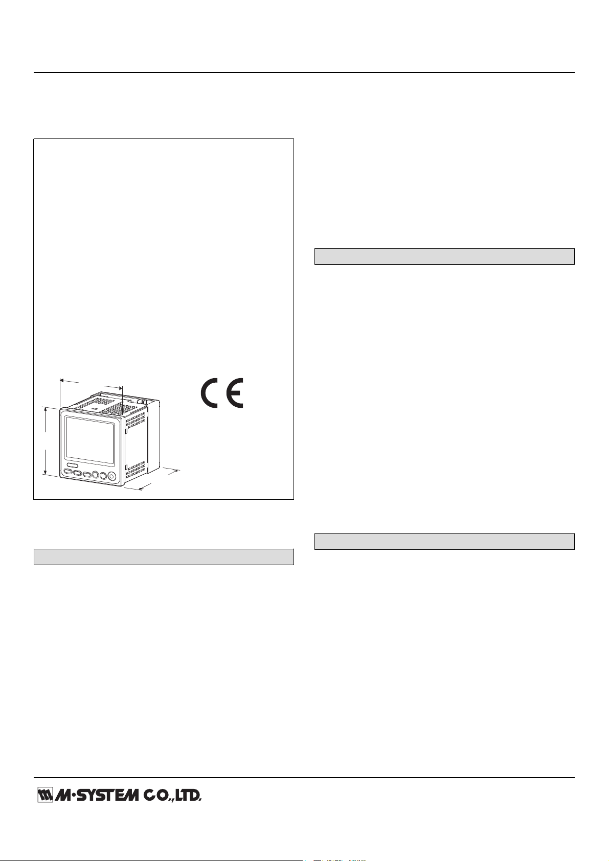
Paperless Recording System
96 (3.78)
mm (inch)
110.5 (4.35)
96
(3.78)
PAPERLESS RECORDER
(color LCD display)
Functions & Features
• 96 mm square size
• Records, displays and sets alarms for 8 analog and 8
contact inputs and 8 contact outputs
• Maps the remote I/O data to logical channels
• Built-in I/O: 2 analog, 3 universal and 2 contact inputs and
2 contact outputs
• Trigger function: Records only necessary part of the data
• Recorded data can be transferred to a PC with memory
cards or COP-IRDA and converted to CSV format with
71VRCFG
• TFT color LCD
• IP65 front panel
• Separable two pieces terminal block
• Safety terminal cover tethered to the device with a strap
• CE marking
MODEL: 71VR1-[1][2]1-[3]
EXTERNAL INTERFACE
1: Modbus
[3] POWER INPUT
AC Power
M2: 100 – 240 V AC (Operational voltage range 85 – 264 V AC, 50/60 Hz)
DC Power
R: 24 V DC
(Operational voltage range 24 V ±10 %, ripple 10 %p-p max.)
P: 110 V DC
(Operational voltage range 85 – 150 V, ripple 10 %p-p max.)
RELATED PRODUCTS
• Precision Resistor Module (model: REM2-50)
Use for mA universal input
• Infrared Communication Adaptor (model: COP-IRDA)
• PC configurator software (model: 71VRCFG)
Downloadable at M-System’s web site.
• Remote I/O R3 series
Modbus interface module (model: R3-NM1)
• Remote I/O R5 series
Modbus interface module (model: R5-NM1)
• Modbus I/O module (model: R7M)
R7 Configurator Software (Model: R7CON)
Modbus communication parameters of the R7M must be
configured by using R7CON and the dedicated cable.
• Devices equipped with Modbus communication. For
detailed information, visit the M-System’s web site.
• Memory card (Hagiwara Sys-Com NSD6-002GT, NSDA004GT)
A memory card is required to store data in the unit.
Use the specified model number of memory card.
ORDERING INFORMATION
• Code number: 71VR1-[1][2]1-[3]
Specify a code from below for each [1] through [3].
(e.g. 71VR1-N101-M2)
[1] LANGUAGE
N: Japanese
E: English
(Language (Japanese or English) can be chose by front
panel setting.)
[2] ANALOG I/O
00: None
10: DC input, 2-points
50: DC input, 2-points,
Universal input, 3-points (V, mA, T/C, RTD)
GENERAL SPECIFICATIONS
Construction: 96-mm square panel flush mounted
Degree of protection: IP65; applicable to the front panel of
the recorder with single mounting according to the specified
panel cutout
Connection: M3 screw terminals (torque 0.5 N·m)
Screw terminal: Nickel-plated steel
Housing material: Flame-resistant resin (black)
Isolation: Analog input each other to contact input to
contact output 1 to contact output 2 to Modbus interface to
power input to FE (Functional Earth)
Number of assignable logical channels
Analog input: 8 points max.
Contact input: 8 points max.
Contact output: 8 points max.
Data storage: Stores Trend and Alarm history in memory
card.
Trend: Stored in files named time and date.
Page 2

MODEL: 71VR1
http://www.m-system.co.jp/ 71VR1 SPECIFICATIONS ES-7403 Rev.6 Page 2/7
60000 samples in one file
[Legend] Y: Selectable, ---: Not selectable
*Selectable when without thermal input settings
Sample rate:
NUMBER OF
MODBUS
LOGICAL
CHANNELS
SAMPLE RATE (sec.)
0
1 to 2
3 to 5
6 to 10
11 to 20
21 to 24
0.1
0.2
0.5
1
2
5
10
Y* Y*
Y*
Y
Y
Y
Y
Y
Y Y
Y
Y
Y Y
Y
Y
Y Y
Y
Y
Y
Y
Y Y
Y
Y
Y
---
--- ---
---
---
---
---
---
---
---
---
---
---
---
---
Overrange input (out of the usable range) is handled as burnout.
T/C
USABLE RANGE (°C)
CONFORMANCE RANGE (°C)
K (CA)
E (CRC)
J (IC)
T (CC)
B (RH)
R
S
-272 to +1472
-272 to +1120
-260 to +1300
-272 to +500
24 to 1920
-100 to +1860
-100 to +1860
-150 to +1370
-170 to +1000
-180 to +1200
-170 to +400
400 to 1760
200 to 1760
0 to 1760
C (WRe 5-26)
N
-52 to +2416
-272 to +1400
0 to 2315
-130 to +1300
U
L
P (Platinel II)
(PR)
-252 to +700
-252 to +1000
-52 to +1496
-52 to +1860
-200 to +600
-200 to +900
0 to 1395
0 to 1760
Overrange input (out of the usable range) is handled as burnout.
RTD
USABLE RANGE (°C)
CONFORMANCE RANGE (°C)
Pt 100 (JIS '97, IEC)
Pt 100 (JIS '89)
JPt 100 (JIS '89)
Pt 50 (JIS '81)
Ni 100
Cu 10 (25°C)
Cu 50
-240 to +900
-240 to +900
-236 to +560
-236 to +700
-100 to +252
-212 to +312
-100 to +200
-200 to +850
-200 to +660
-200 to +510
-200 to +649
-80 to +250
-50 to +250
-50 to +150
Storage capacity: 200 files max.
Storage time:
Approx. 13 days at storing rate 0.1 sec.,
approx. 138 days at 1 sec.,
approx. 1388 days at 10 sec.
Alarm history: Stored in alarm history file, 200 items max.
■ DISPLAY
Display device: 3.5-inch TFT LCD
Display colors: 256
Resolution: 320 × 240 pixels
Backlight: LED
Display update interval: 500 msec.
(Range: Input resistance)
-1 – +1V: ≥ 1MΩ
-5 – +5V: ≥ 1MΩ
-10 – +10V: ≥ 1MΩ
■ CONTACT INPUT (Di1, Di2): Dry contact, 2 points
Input resistance: Approx. 1.8 kΩ
Common: Negative
Sensing: 12 V DC
ON current/resistance: ≥ 1.5 mA, ≤ 1.5 kΩ
OFF current/resistance: ≤ 0.75 mA, ≥ 15 kΩ
[Table 1 (Thermocouple input)]
[Table 2 (RTD input)]
INPUT SPECIFICATIONS
■ UNIVERSAL INPUT (Ai3, Ai4, Ai5)
• DC current input
(Range: Input resistance)
-20 – +20 mA: 50 Ω (separately provided REM2)
• DC voltage input
(Range: Input resistance)
-1 – +1 V: ≥ 1 MΩ
-5 – +5 V: ≥ 1 MΩ
-10 – +10 V: ≥ 1 MΩ
• Thermocouple input: K, E, J, T, B, R, S, C, N, U, L, P, PR
(See Table 1.)
Input resistance: ≥ 30 kΩ
Burnout sensing: ≤ 0.1 μA
Burnout indication: Maximum value (upscale burnout)
of the usable range
• RTD input: Pt 100 (JIS ’97, IEC), Pt 100 (JIS ’89), JPt 100 (JIS
’89), Pt 50Ω (JIS ’81), Ni 100, Cu 10, Cu 50 (See Table 2.)
Input resistance: ≥ 1 MΩ
Maximum leadwire resistance: 100 Ω per wire
Burnout indication: Maximum value (upscale burnout) of the
usable range
Sensing current: ≤ 1 mA
■ DC CURRENT INPUT (Ai1, Ai2)
(Range: Input resistance)
-20 – +20 mA: 100 Ω (incorporated)
■ DC VOLTAGE INPUT (Ai1, Ai2)
OUTPUT SPECIFICATIONS
■ NETWORK INTERFACE
• Modbus-RTU: Retrievable analog data is Int data (signed
16 bits) only.
Transmission: Half-duplex, asynchronous, no procedure
Interface: Conforms to EIA RS-485
Max. transmission distance: 500 meters
Baud rate: 4800, 9600, 19200, 38400 bps
Data bit: 8 bits
Parity: Odd
Stop bit: 1 bit
Max. number of nodes: 15 (except the master)
Media: Shielded twisted-pair cable (CPEV-S 0.9 dia.)
• Infrared Interface
Interface: IrDA
Max. transmission distance: ≤ 0.2 m (with COP-IRDA and
71VRCFG)
■ CONTACT OUTPUT (Do1, Do2)
• Relay Output
Relay rating:
Page 3

MODEL: 71VR1
http://www.m-system.co.jp/ 71VR1 SPECIFICATIONS ES-7403 Rev.6 Page 3/7
250 V AC @5 A (cos ø = 1)
30 V DC @5 A (resistive load)
Maximum switching voltage: 250 V AC or 30 V DC
Maximum switching power: 65 VA or 60 W
Minimum load: 5 V DC @10 mA
Mechanical life: 2 × 10⁷ cycles
INSTALLATION
Power Consumption
•AC power input:
Approx. 7 VA at 100 V
Approx. 10 VA at 240 V
•DC power input: Approx. 6 W
Operating temperature: -5 to +55°C (23 to 131°F)
Operating humidity: 30 to 90 %RH (non-condensing)
Atmosphere: No corrosive gas or heavy dust
Mounting: Panel flush mounting
Weight: 550 g (1.2 lbs)
PERFORMANCE
Conversion accuracy
DC input: ±0.1% ±1 digit
Thermocouple input: ±1°C (±2°C for B, R, S, C, PR)
RTD input: ±1°C (±3°C for Cu 10)
CJC error: ±2°C max. at 25°C ±10°C
±4°C max. for R, S, PR
Temp. coefficient: ±0.015 %/°C (±0.008 %/°F)
±0.05 %/°C (±0.03 %/°F) for Cu 10
Response time: ≤ 0.5 sec. for DC input with the sample
rate set to 100 msec.
≤ 2.5 sec. for T/C, RTD input with the sample
rate set to 500 msec.
Response time of alarm output, 0 – 100 % at 90 % setpoint.
Line voltage effect: ±0.1 % over voltage range
Calendar clock accuracy: Monthly deviation 2 minutes at
25°C
Battery backup: Approx. one month
Insulation resistance: ≥ 100 MΩ with 500 V DC
(Analog input each other to contact input to contact output
1 to contact output 2 to Modbus interface to power input to
FE)
Dielectric strength: 2000V AC @1 minute
(Analog input each other to contact input to contact output
1 to contact output 2 to Modbus interface to power input to
FE)
Low Voltage Directive (2006/95/EC)
EN 61010-1
Installation Category II
Pollution Degree 2
Max. operating voltage 300 V
Analog input or contact input or contact output or network
interface to power to FG: Reinforced insulation
Analog input each other to contact input to contact output
each other to network interface: Basic insulation
Protection against access to the terminal blocks:
Finger protection (VDE 0660-514)
STANDARDS & APPROVALS
CE conformity:
EMC Directive (2004/108/EC)
EMI EN 61000-6-4
EMS EN 61000-6-2
Page 4

MODEL: 71VR1
http://www.m-system.co.jp/ 71VR1 SPECIFICATIONS ES-7403 Rev.6 Page 4/7
EXTERNAL VIEW
■ REAR VIEW
■ FRONT VIEW
1
2
3
4
5
6
7
8
9
10
21
22
23
24
25
26
27
28
29
30
F1 F2 F3
F4 F5
F6
MEM
Memory Card Slot
Display
Infrared
Communication Port
Control Buttons
11
12
13
14
15
16
17
18
19
20
The terminals for number 11 through 20 are only with 5-points input.
RS-485
DA
DB
DG
SLD
FG
R7M
RS-485
DA
DB
DG
SLD
FG
R7M
71VR1
T1
T2
T3
T4
*1. Use a terminating resistor when the device is at the extreme end of a transmission line.
Terminator
*
1
92 (3.62)
98 (3.86)
2 (.08)
100 (3.94)
1
2
3
4
5
6
7
8
9
10
21
22
23
24
25
26
27
28
29
30
MOUNTING BRACKET
TERMINAL COVER
6-M3 SCREW
30-M3 SCREW TERMINAL
96 (3.78)
110 (4.33 )
96 (3.78)
WATERTIGHT SEALING
92 (3.62)
10.5
(.41)
11
12
13
14
15
16
17
18
19
20
The terminals for number 11 through 20 are
only with 5-points input.
MODBUS WIRING CONNECTION
EXTERNAL DIMENSIONS & TERMINAL ASSIGNMENTS unit: mm (inch)
Page 5

MODEL: 71VR1
http://www.m-system.co.jp/ 71VR1 SPECIFICATIONS ES-7403 Rev.6 Page 5/7
MOUNTING REQUIREMENTS unit: mm (inch)
92
92
+0.8 (3.65)
0 (3.63)
+0.8 (3.65)
0 (3.63)
Usable panel thickness: 0.5 – 10 mm (0.02 to 0.39 inch)
■PANEL CUTOUT
Page 6

MODEL: 71VR1
http://www.m-system.co.jp/ 71VR1 SPECIFICATIONS ES-7403 Rev.6 Page 6/7
SCHEMATIC CIRCUITRY & CONNECTION DIAGRAM
VOLTAGE INPUT
+
–
CURRENT INPUT
+
–
I
COM
V
I
COM
V
*1. Only with 5-point inputs
*2. Only with 2-point DC inputs
*3. When the device is located at the end of a transmission line
via twisted-pair cable (when there is no cross-wiring), close across the terminals T2 - T3 with a leadwire.
NOTE: Short across the terminals V and I for Current Input.
V
I
COM
V
I
COM
9
10
27
30
28
29
Digital
Computation
2
3
4
5
6
7
8
1
FE
*
1
*
2
SHLD
T4
T1
T2
T3
11
A1
B1
C1
A2
B2
C2
A3
B3
C3
13
12
14
16
15
17
19
18
• Universal Input
A
B
B
RTD
A
B
A
B
C
A
B
C
A
B B
C
A
B
CAC
T/C
REM2
-
CJC SENSOR
C
COM
21
23
22
24
26
25
■ INPUT CONNECTION E.G.
NOTE: For mA input, the REM2 is required.
+ + +
–
–
VOLTAGE INPUT
CURRENT INPUT
• DC Input
U(+)
V(–)
POWER
CONTACT OUTPUT Do 1
CONTACT OUTPUT Do 2
Jumper
*
3
+
–
+
+
–
CONTACT INPUT Di 1
COM
CONTACT INPUT Di 2
Contact
Input
Circuit
DC INPUT Ai 1
DC INPUT Ai 2
UNIVERSAL
INPUT
Ai 3
UNIVERSAL
INPUT
Ai 4
UNIVERSAL
INPUT
Ai 5
A/D
Converter
A/D
Converter
A/D
Converter
A/D
Converter
A/D
Converter
Isolation
Isolation
Isolation
Display / Setting
Communication
Circuit
Isolation
Isolation
Memory Card Slot
Shielded
Twisted-pair Cable
To other
Modbus devices
Page 7

MODEL: 71VR1
http://www.m-system.co.jp/ 71VR1 SPECIFICATIONS ES-7403 Rev.6 Page 7/7
SYSTEM CONFIGURATION EXAMPLES
RS-485 (Modbus-RTU)
・・・・・・・・・・・・・・・・・・・・
*1. Insert lightning surge protectors recommended in this example if necessary.
Paperless Recorder (model: 71VR1)
Modbus I/O Module (model: R7M)
Modbus I/O Module (model: R7M)
Lightning Surge Protector for RS-485/422
(model: MD74R or MDP-4R)
*
1
Lightning Surge Protector for RS-485/422
(model: MD74R or MDP-4R)
*
1
Specifications are subject to change without notice.
 Loading...