

Page 1
INSTRUCTION MANUAL
4-DIGIT LOOP POWERED INDICATOR
(outdoor enclosure, intrinsically safe/explosion-proof)
BEFORE USE ....
Thank you for choosing M-System. Before use, please check
contents of the package you received as outlined below.
If you have any problems or questions with the product,
please contact M-System’s Sales Office or representatives.
■ PACKAGE INCLUDES:
Loop Powered Indicator ......................................................(1)
Mounting screws .................................................................(4)
Unit label ...................................................................(1) sheet
Mounting bracket assembly (optional)
Mounting bracket ..............................................................(1)
M10 U-bolt .........................................................................(2)
Nut for M10 .......................................................................(4)
Spring washer for M10 .....................................................(4)
Cable glands (TIIS explosion-proof approval option) ........(2)
Stopping plug (TIIS explosion-proof approval option) ......(1)
■ MODEL NO.
Confirm Model No. marking on the product to be exactly
what you ordered.
■ INSTRUCTION MANUAL
This manual describes necessary points of caution when
you use this product, including installation, connection and
basic maintenance procedures.
When using this product in potentially explosive atmosphere or hazardous (classified) location, you have to follow
the safety procedure to install it. Please refer to “SAFE INSTALLATION MANUAL” for each type of certification.
POINTS OF CAUTION
■ CONFORMITY WITH EU DIRECTIVES
• The actual installation environments such as panel configurations, connected devices, connected wires, may affect the protection level of this unit when it is integrated
in a panel system. The user may have to review the CE
requirements in regard to the whole system and employ
additional protective measures to ensure the CE conformity.
■ GENERAL PRECAUTIONS
• Before you remove the module, turn off the input signal
for safety.
■ ENVIRONMENT
• Do not install the module where it is subjected to continuous vibration. Do not subject the module to physical
impact.
• Environmental (non-hazardous location) temperature
must be within -40 to +85°C (-40 to +185°F) with relative
humidity within 0 to 95% RH in order to ensure adequate
life span and operation.
• Seal unused electrical wiring conduits.
• For use in a hazardous location, be sure that the environmental temperature is within the temperature class
required for the area.
■ WIRING
• Do not install cables close to noise sources (relay drive
cable, high frequency line, etc.).
• Do not bind these cables together with those in which
noises are present. Do not install them in the same duct.
• When the unit is used in an environment where inductive noise interference is expected, ground the earthing
terminal.
MODEL
6DV-B/6DVI-B
■ AND ....
• The module is designed to function as soon as input signal is supplied, however, a warm up for 10 minutes is required for satisfying complete performance described in
the data sheet.
5-2-55, Minamitsumori, Nishinari-ku, Osaka 557-0063 JAPAN
Phone: +81(6)6659-8201 Fax: +81(6)6659-8510 E-mail: [email protected]
EM-4220-A Rev.9 P. 1 / 8
Page 2

COMPONENT IDENTIFICATION
■ WITHOUT TERMINAL BLOCK (Euro terminal block at the rear of indicator module)
• When the indicator is removed
Internal Earthing Screw
Cover
Indicator
Screw(s)
Specifications (top)
Wiring Conduit
Case
6DV-B / 6DVI-B
External Earthing Screw
■ WITH TERMINAL BLOCK
Cover
Indicator
External Earthing Screw
Specifications (top)
Screw
Wiring Conduit
Case
• Rear view of the indicator
Euro Terminal
Block
1234
• When the indicator is extracted
Internal Earthing Screw
Terminal
Block
.
5-2-55, Minamitsumori, Nishinari-ku, Osaka 557-0063 JAPAN
Phone: +81(6)6659-8201 Fax: +81(6)6659-8510 E-mail: [email protected]
EM-4220-A Rev.9 P. 2 / 8
Page 3
TOP VIEW
6DV-B / 6DVI-B
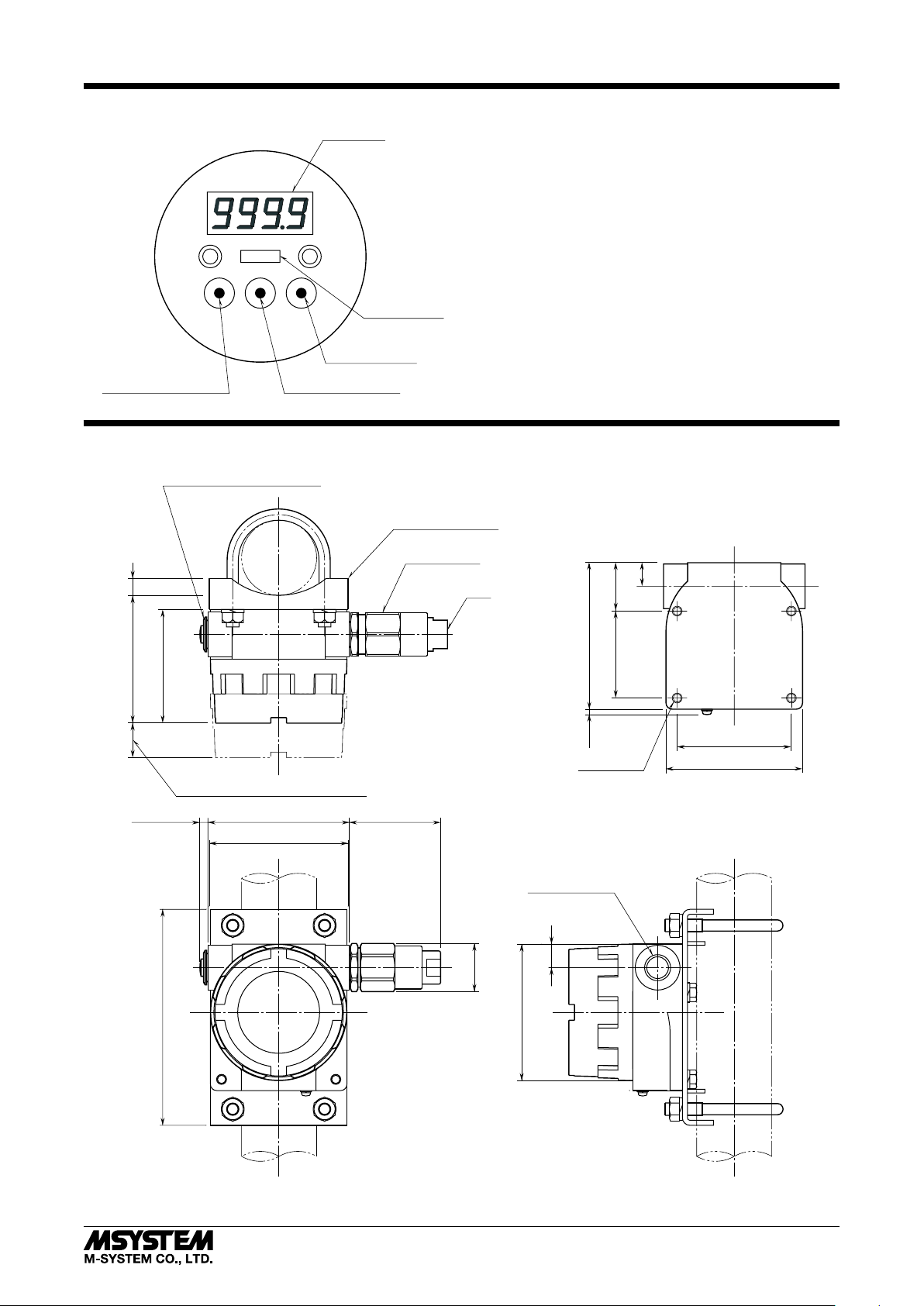
Data Display
°C
ENTR / ESC Button
• Used to call up the program menu and to apply parameter changes. (Press for longer than 2 seconds.)
• Used to cancel menu selections and to cancel parameter
changes. (Push for a brief period.)
BACK / DOWN Button: Used to select a menu item or to
decrease parameter values.
NEXT / UP Button: Used to select a menu item or to increase
parameter values.
ENTR / ESC BACK / DOWN NEXT / UP
ENTER / ESCAPE Button BACK / DOWN Button
Engineering Unit
NEXT / UP Button
EXTERNAL DIMENSIONS unit: mm (inch)
14
26
STOPPING PLUG (TIIS flameproof)
(.55)
104 (4.09)
92 (3.62)
(1.02)
SPACE REQUIRED TO REMOVE COVER
*
MOUNTING BRACKET
(optional)
CABLE GLAND
(TIIS flameproof)
• How to Reset All Parameters to the Factory Setting
Turn off the power supply to the module. In pressing all the
three control buttons at once, turn it on. When a message
appears on the data display, press ENTR / ESC. If you want
to cancel the procedure, turn the power supply off.
*
G 1/2
118 (4.65)
max.
7 (.28)
4–M8, 12 deep
39 (1.54)
70 (2.76)
19 (.75)
92 (3.62)
110 (4.33)
approx. 7 (.28)
174 (6.85)
114 (4.49)
110 (4.33)
*Two cable glands and one plug are provided with TIIS flameproof type.
Use them according to the field wiring requirements.
5-2-55, Minamitsumori, Nishinari-ku, Osaka 557-0063 JAPAN
Phone: +81(6)6659-8201 Fax: +81(6)6659-8510 E-mail: [email protected]
max. 86.5 (3.41)
dia.
39 (1.54)
2–G1/2, 1/2NPT,
M20x1.5 or PG13.5
110 (4.33) dia.
19 (.75)
EM-4220-A Rev.9 P. 3 / 8
Page 4
INSTALLATION
AB
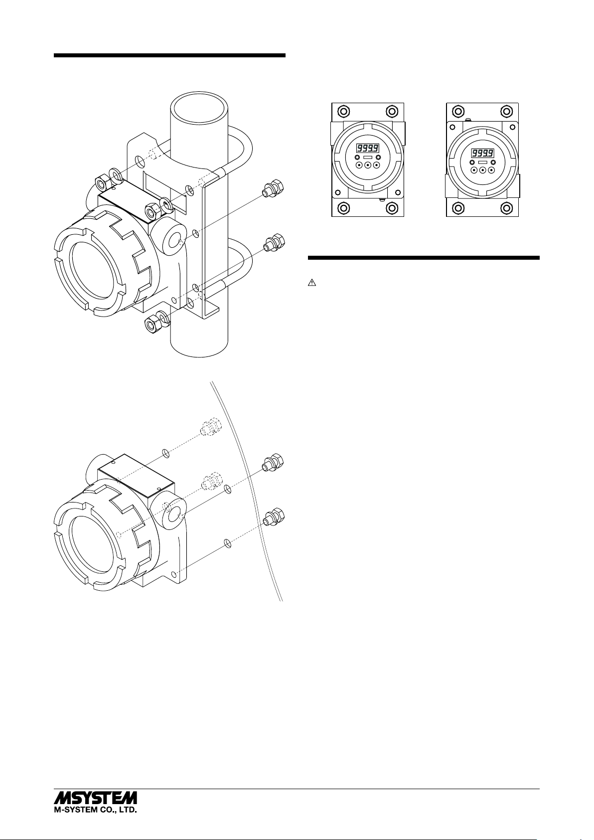
■ MOUNTING THE ENCLOSURE ON A PIPE
6DV-B / 6DVI-B
■ MOUNTING DIRECTION
The LED indicator can be mounted in two different directions in relation to the position of the external earthing
screw.
TERMINAL CONNECTION
Warning!
For use in a hazardous location, refer to “Installation Diagram”
in the “Safe Installation Manual.”
■ MOUNTING THE ENCLOSURE ON A WALL
■ WITHOUT TERMINAL BLOCK
1) Loosen the screws on top of the indicator and separate
the indicator module from the case.
2) Fasten wires to terminals at the rear side of the indicator.
Applicable wire size: 0.14 to 1.5mm
Stripped length: 6 mm (0.27”)
Recommended pin terminal: Phoenix Contact AI0,25-6BU
3) Put the indicator module back inside the case and tighten
with the screws. (torque: 0.8 N·m)
■ WITH TERMINAL BLOCK
1) Loosen the screw on the left side of the indicator and
extract the indicator module from the case.
2) Fasten wires to terminal block. (torque: 0.5 N·m)
3) Put the indicator module back inside the case and tighten
with the screw. (torque: 0.8 N·m)
2
(AWG26 to 16)
5-2-55, Minamitsumori, Nishinari-ku, Osaka 557-0063 JAPAN
Phone: +81(6)6659-8201 Fax: +81(6)6659-8510 E-mail: [email protected]
EM-4220-A Rev.9 P. 4 / 8
Page 5
6DV-B / 6DVI-B
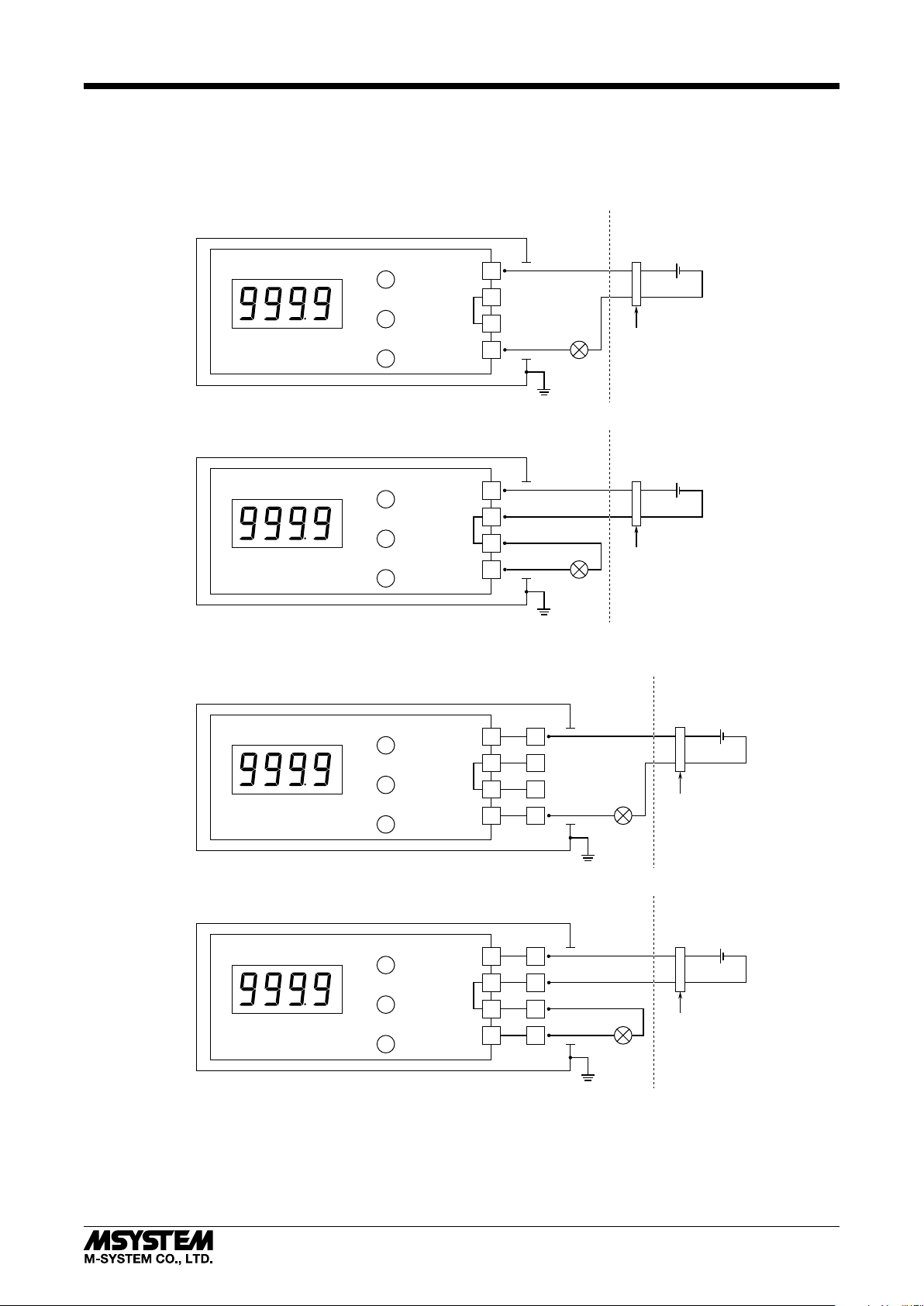
CONNECTION DIAGRAM
For use in potentially explosive atmosphere or in hazardous (classified) locations, please follow instructions in ‘SAFE INSTALLATION MANUAL’ provided separately for each type of certification.
■ 2-WIRE CONNECTION EXAMPLE
• WITHOUT TERMINAL BLOCK (Euro terminal block at the rear of indicator module)
Hazardous Location
Non-Hazardous
Location
• WITH TERMINAL BLOCK
LED Display
LED Display
ENTR / ESC
BACK / DOWN
NEXT / UP
ENTR / ESC
BACK / DOWN
NEXT / UP
Internal
Bridge
Internal
Bridge
+
1
2
3
4
–
Transmitter
Hazardous Location
+
1
2
–
3
4
Transmitter
Hazardous Location
+–
Two-wire
+–
Two-wire
Power Source
Safety Barrier
Non-Hazardous
Location
Power Source
Safety Barrier
Non-Hazardous
Location
1
*
1
*
LED Display
3
*
LED Display
*1.
A safety barrier must be installed for the intrinsic safety.
The safety barrier must meet the Ex-data of this unit and must be approved for the hazardous location.
In order to use a two-wire transmitter in the TIIS intrinsically safe circuit, the combination of the 6DV-B
*2.
with the transmitter must be re-evaluated and approved by the TIIS.
This connection digram is not applicable for the TIIS intrinsic safety.
*3.
ENTR / ESC
BACK / DOWN
NEXT / UP
ENTR / ESC
BACK / DOWN
NEXT / UP
Internal
Bridge
Internal
Bridge
1
2
3
4
1
2
3
4
+
9
10
11
12
9
10
2
–
*
Hazardous Location
+
–
11
12
+–
Two-wire
Transmitter
+–
Two-wire
Transmitter
Power Source
Safety Barrier
Non-Hazardous
Location
Power Source
Safety Barrier
1
*
1
*
5-2-55, Minamitsumori, Nishinari-ku, Osaka 557-0063 JAPAN
Phone: +81(6)6659-8201 Fax: +81(6)6659-8510 E-mail: [email protected]
EM-4220-A Rev.9 P. 5 / 8
Page 6
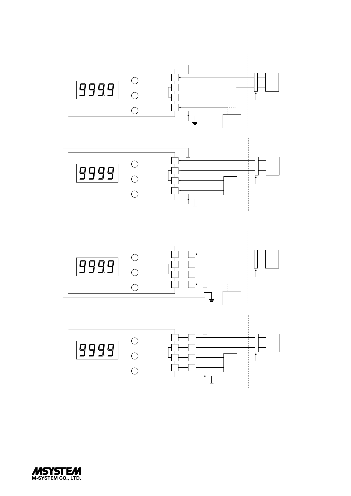
■ 4-WIRE CONNECTION EXAMPLE
• WITHOUT TERMINAL BLOCK (Euro terminal block at the rear of indicator module)
Hazardous Locatio
LED Display
LED Display
ENTR / ESC
BACK / DOWN
NEXT / UP
ENTR / ESC
BACK / DOWN
NEXT / UP
Internal
Bridge
Internal
Bridge
+
1
2
3
4
–
+
1
2
–
3
4
4 – 20mA DC
I/P Positioner, etc.
Hazardous Locatio
4 – 20mA DC
–
+
I/P Positioner, etc.
–+
6DV-B / 6DVI-B
Non-Hazardous
Locatio
Controllor, etc.
+
–
Safety Barrier
Non-Hazardous
Locatio
Controllor, etc.
+
–
Safety Barrier
4
*
4
*
• WITH TERMINAL BLOCK
LED Display
6
*
LED Display
ENTR / ESC
BACK / DOWN
NEXT / UP
ENTR / ESC
BACK / DOWN
NEXT / UP
Internal
Bridge
Internal
Bridge
Hazardous Locatio
4 – 20mA DC
I/P Positioner, etc.
Hazardous Locatio Non-Hazardous
4 – 20mA DC
–
+
I/P Positioner, etc.
10
11
12
10
11
12
+
9
–
+
9
–
1
2
3
4
1
2
3
4
–+
*
Non-Hazardous
Locatio
Controllor, etc.
+
–
Safety Barrier
5
Locatio
Controllor, etc.
+
–
Safety Barrier
4
*
4
*
*4.
A safety barrier must be installed for the intrinsic safety.
The safety barrier must meet the Ex-data of this unit and must be approved for the hazardous location.
In order to use a two-wire transmitter, etc. in the TIIS intrinsically safe circuit, the combination of the 6DV-B
*5.
with the transmitter must be re-evaluated and approved by the TIIS.
This connection digram is not applicable for the TIIS intrinsic safety.
*6.
5-2-55, Minamitsumori, Nishinari-ku, Osaka 557-0063 JAPAN
Phone: +81(6)6659-8201 Fax: +81(6)6659-8510 E-mail: [email protected]
EM-4220-A Rev.9 P. 6 / 8
Page 7
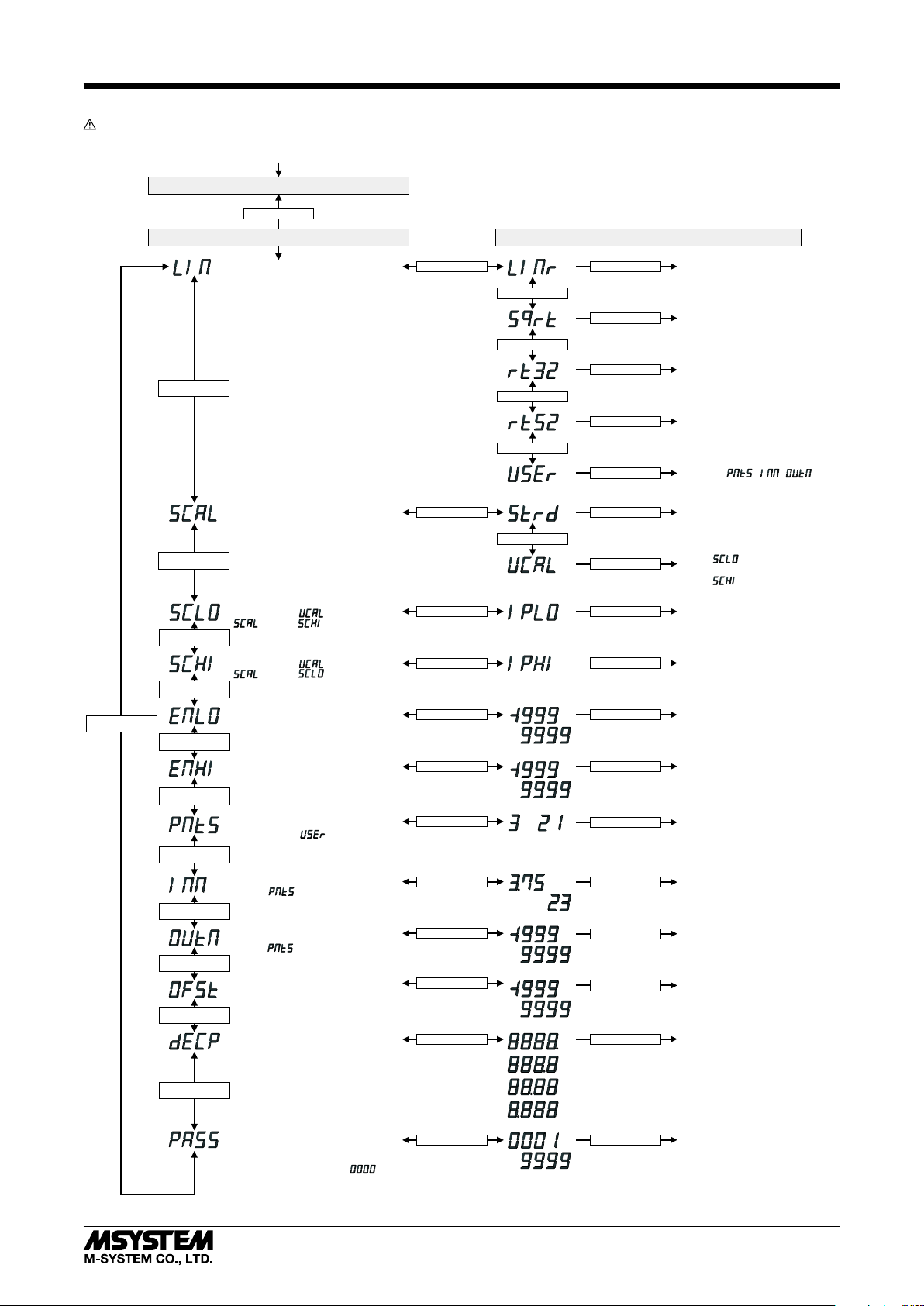
PROGRAMMING PROCEDURE
Program the unit without explosive atmosphere.
6DV-B / 6DVI-B
NEXT / UP
BACK / DOWN
NEXT / UP
BACK / DOWN
NEXT / UP
BACK / DOWN
NEXT / UP
NEXT / BACK
BACK / DOWN
NEXT / UP
BACK / DOWN
NEXT / UP
BACK / DOWN
NEXT / UP
BACK / DOWN
NEXT / UP
BACK / DOWN
NEXT / UP
BACK / DOWN
NEXT / UP
BACK / DOWN
NEXT / UP
BACK / DOWN
NEXT / UP
BACK / DOWN
INPUT SIGNAL ON
DISPLAY MODE *
ENTR / ESC
MENU MODE PARAMETER MODE
LINEARIZATION TYPE
INPUT RANGE CALIBRATION
Standard (4 – 20mA) or
User’s input range
0% INPUT CALIBRATION
Applicable when is selected for
setting (< )
100% INPUT CALIBRATION
Applicable when is selected for
setting (> )
0% SCALING
Display range at 0% input
100% SCALING
Display range at 100% input
USER’S LINEARIZATION
–CALIBRATION POINTS
Applicable when is selected
for LINEARIZATION TYPE
USER’S LINEARIZATION
–nth INPUT VALUE (mA)
(1 ≤ n ≤ )
USER’S LINEARIZATION
–nth SCALED VALUE
(1 ≤ n ≤ )
OFFSET
Added to the scaled value.
DECIMAL POINT POSITION
May shift according to the required
number of digits for the integer section,
even when more than one decimal places
have been specified.
1
ENTR / ESC
ENTR / ESC
ENTR / ESC
ENTR / ESC
ENTR / ESC
ENTR / ESC
ENTR / ESC
ENTR / ESC
ENTR / ESC
ENTR / ESC
ENTR / ESC
■ BUTTON OPERATION
ENTR / ESC Button
• Used to call up the program menu and to apply parameter changes.
(Press for longer than 2 seconds.)
• Used to cancel menu selections and to cancel parameter changes.
(Push for a brief period.)
BACK / DOWN Button: Used to select a menu item or to decrease parameter values.
NEXT / UP Button: Used to select a menu item or to increase parameter values.
ENTR / ESC
NEXT / BACK
ENTR / ESC
NEXT / BACK
ENTR / ESC
NEXT / BACK
ENTR / ESC
NEXT / BACK
ENTR / ESC
ENTR / ESC
NEXT / BACK
ENTR / ESC
ENTR / ESC
ENTR / ESC
ENTR / ESC
...
Use NEXT / UP, BACK DOWN buttons.
ENTR / ESC
...
Use NEXT / UP, BACK DOWN buttons.
...
Use NEXT / UP, BACK DOWN buttons.
...
Use NEXT / UP, BACK DOWN buttons.
Use NEXT / UP, BACK DOWN buttons.
Use NEXT / UP, BACK DOWN buttons.
ENTR / ESC
ENTR / ESC
ENTR / ESC
...
ENTR / ESC
...
ENTR / ESC
Proportional to the input (linear)
1/2
SQRT (X
)
3/2
)
RT32 (X
5/2
RT52 (X
)
User’s Linearization Table
defined by , ,
is applied.
0% : Set to 4mA
100% : Set to 20mA
0% : The value selected by
is applied.
100% : The value selected by
is applied.
0% input value is set.
100% input value is set.
Display value at 0% input
is set.
Display value at 100% input
is set.
Number of calibration points
is set.
The Nth input value is set
in mA.
The scaled value for the n
input is set.
Offset value is set.
Decimal point position is set.
th
SECURITY CODE
Set a four-digit number to protect the
user’s configurations. MENU MODE is
available only when the code is entered.
The lockout is canceled when is set.
*1. Scaling value is displayed with the value fixed by 0% scaling, 100% scaling and number of digit after the decimal point specified by decimal point position.
5-2-55, Minamitsumori, Nishinari-ku, Osaka 557-0063 JAPAN
Phone: +81(6)6659-8201 Fax: +81(6)6659-8510 E-mail: [email protected]
ENTR / ESC
Use NEXT / UP, BACK DOWN buttons.
...
Use NEXT / UP, BACK DOWN buttons.
ENTR / ESC
Security code is set.
EM-4220-A Rev.9 P. 7 / 8
Page 8
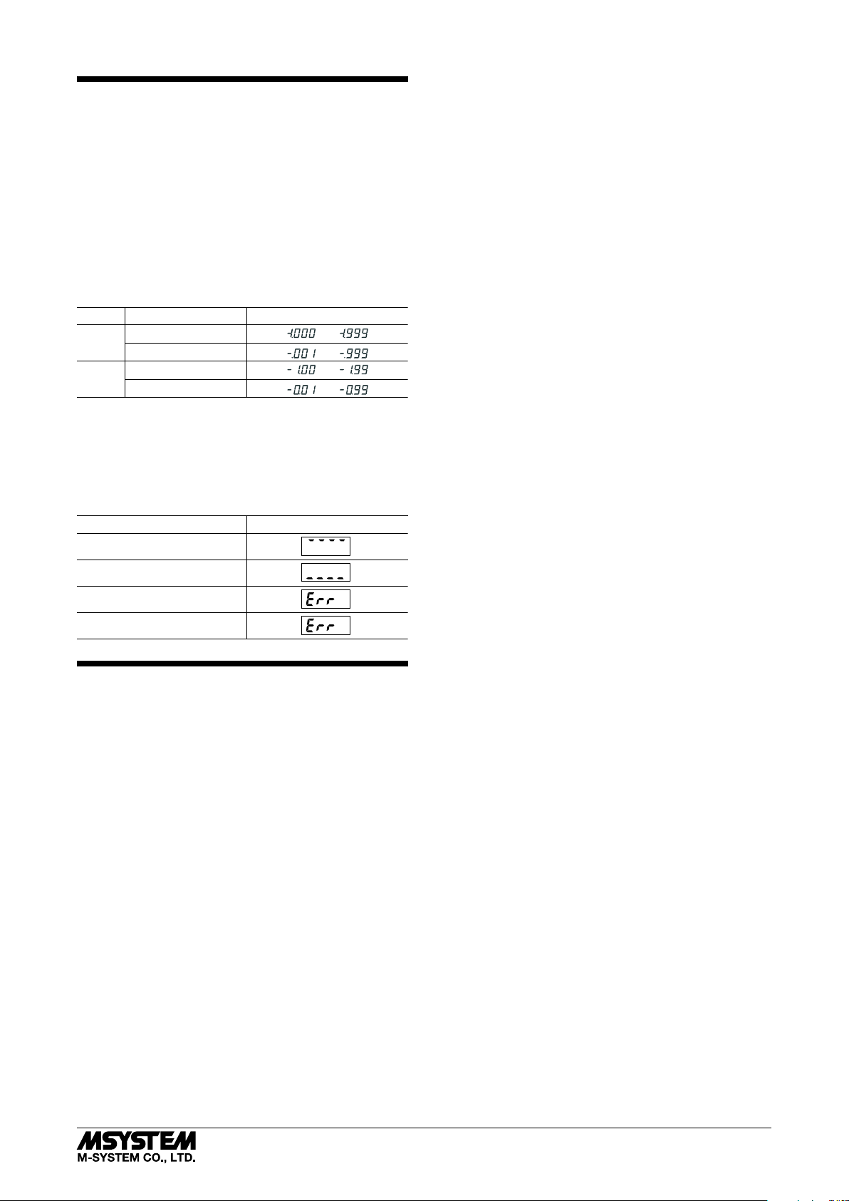
LED DISPLAY
■ DISPLAY DIGITS
The decimal point position may shift according to the required number of digits for the integer section, even when
more than one decimal places have been specified.
However, when the number of decimal places is set to 3, the
‘0’ in the integer section is not shown in order to secure the
number of effective digits, as explained in the table below.
The ‘0’ is displayed when the number of decimal places is
set to 2, though the number of effective digits in this case
is reduced by 1 digit compared from the 3 decimal places.
Select appropriately for the application. Refer to ‘Programming Procedure’ for how to choose decimal point positions.
DECIMAL
3
2
■ ERROR INDICATION
The data display blinks when an abnormality is detected.
The unit display backlight also blinks.
When the setting error or the security code error occurs,
press ENTR / ESC button once to cancel the error status
and proceed to set again.
Over-scale
VALUE
-1.000 thr. -1.999
-0.001 thr. -0.999
-1.00 thr. -1.99
-0.01 thr. -0.99
DATA DISPLAY
...
...
...
...
DATA DISPLAYERROR TYPE
6DV-B / 6DVI-B
Under-scale
Setting error
Security code error
LIGHTNING SURGE PROTECTION
M-System offers a series of lightning surge protectors for
protection against induced lightning surges. Please contact
M-System to choose appropriate models.
5-2-55, Minamitsumori, Nishinari-ku, Osaka 557-0063 JAPAN
Phone: +81(6)6659-8201 Fax: +81(6)6659-8510 E-mail: [email protected]
EM-4220-A Rev.9 P. 8 / 8
 Loading...