

Page 1

MODEL: 6DV-B
http://www.m-system.co.jp/ 6DV-B SPECIFICATIONS ES-4220 Rev.14 Page 1/7
Field-mounted Two-wire Signal Conditioners 6-UNIT
■
SELECTABLE WIRING CONDUITS SPECIFIC TO EACH APPROVAL
‘N’ marked combinations are not selectable.
APPROVAL
WIRING
0 1 2 3 4 7 8
CONDUIT
0 Y Y Y N N Y Y
1 Y Y Y Y Y Y N
2 Y Y Y N Y Y N
3 Y Y Y N N Y N
4-DIGIT LOOP POWERED INDICATOR
(outdoor enclosure, intrinsically safe/explosion-proof)
Functions & Features
• 4-digit LED display
• No external power source needed
• Scaling, linearization and other configurations selectable
via three front control buttons
• Stainless steel enclosure optional
Note: Differences between the 6DV-B and the 6DVI-B exist
only in safety parameters. Refer to the relevant section for
more information.
[2] TERMINAL BLOCK
0: None (Euro terminal block at the rear of indicator module)
(TIIS flameproof or TIIS intrinsically safe approvals not selectable)
T: Incorporated
[3] WIRING CONDUIT
0: G 1/2
1: 1/2 NPT
2: M20 × 1.5
3: PG 13.5
Confirm selectable combinations of approval and wiring
conduit types in the table.
[4] MOUNTING BRACKET
0: Without
1: With
[5] OPTIONS
Enclosure Materials
Blank: Diecast aluminium enclosure
/S: Stainless steel enclosure
(TIIS flameproof approval not selectable)
MODEL:6DV–B–[1][2][3][4][5]
ORDERING INFORMATION
• Code number: 6DV-B-[1][2][3][4][5]
Specify a code from below for each [1] through [5].
(e.g. 6DV-B-0T01/S)
• Use Ordering Information Sheet (No. ESU-4220). Factory
standard setting will be used if not otherwise specified.
• Specify the country in which the product is to be used with
the Safety Approval code 2 or 4.
[1] SAFETY APPROVAL
0: None
1: FM intrinsically safe
2: CENELEC intrinsic safety (ATEX)
3: FM explosion-proof
4: CENELEC flameproof (ATEX)
7: TIIS intrinsic safety (CE not available)
8: TIIS flameproof (CE not available)
Confirm selectable combinations of approval and wiring
conduit types in the table.
RELATED PRODUCTS
• Cable gland (model: BX-E-SXY)
• Stopping plug (model: BX-E-SBP)
GENERAL SPECIFICATIONS
Degree of protection: NEMA 4X, IP66/IP67
Wiring conduit: See ‘Ordering information.’
Cable gland: Two provided for TIIS flameproof type
Model No.: BX-E-SXY
Cable entries: Elastomeric sealing rings
Wiring conduit size: G 1/2
Material: Chrome-plated brass (entry)
CR (sealing ring)
Applicable wire size: 8 – 12 dia.
Stopping plug: One provided for TIIS flameproof type
Model No.: BX-E-SBP
Wiring conduit size: G 1/2
Page 2
MODEL: 6DV-B
http://www.m-system.co.jp/ 6DV-B SPECIFICATIONS ES-4220 Rev.14 Page 2/7
Material: Diecast aluminium (plug)
NBR (O-ring)
Electrical connection: Euro terminal block (Applicable wire
size: AWG26 – 16, 0.14 – 1.5 mm2) or M3 screw terminal
(torque 0.5 N·m)
Materials
Meter housing: Flame-resistant resin (black)
Enclosure: Diecast aluminium standard; stainless steel
casting optional (equivalent to type 316); silver color, epoxy
resin coated
Mounting bracket assembly:
Stainless steel 304 (for aluminum enclosure)
Stainless steel 316 (for stainless steel enclosure)
Applicable pipe: 1 1/2” min.; 2” max.
Isolation: Input to outdoor enclosure
Linearization: Proportional, SQRT (X
5/2
(X
), user’s linearization table (max. 21 calibration points)
(Default setting: Proportional)
A/D conversion: Dual-slope integration
Security: Protecting settings
Scaling: Programming via the front buttons
1/2
), RT32 (X
3/2
), RT52
DISPLAY
LED: 8 mm (.3”) 7-segment, red
Number of display digits: 4
Scaling range: -1999 to 9999 counts
Offset range: -1999 to 9999 counts
Decimal point position: 10-1, 10-2, 10-3 or none
Polarity sign: Minus (–) sign added automatically according
to the computation result
Over-range warning: All segments dark except the top ones
that blink with the input exceeding the display/measurable
range; or the bottom ones that blink with the input below
the range.
Read rate: 2.5/s
Engineering unit indication: Sticker label attached
DC, AC, mV, V, kV, mA, A, kA, mW, W, kW, var, kvar, Mvar,
mm, m, m/sec, ℓ, ℓ/min, ℓ/h, m3/sec, m3/h, kg/h, t/h, kg, Pa,
kPa, MPa, bar, Psi, t, ℃, °F, K, %RH, pH, %, ppm, etc.
INPUT SPECIFICATIONS
■ DC Current: 4 – 20 mA DC
Measurable range: 3.75 – 23 mA DC
Maximum input current
Non-approved: 100 mA
Explosion-proof: 23 mA
Intrinsically safe: Refer to ‘Safety Parameters.’
Voltage drop: Approx. 3.7 V with 4 mA
Approx. 4.0 V with 20 mA
The minimum required supply voltage to the 2-wire
transmitter added with the indicator’s voltage drop at the
maximum input current must be within the output voltage
range of the 2-wire transmitter’s excitation supply.
INSTALLATION
Operating temperature: -40 to +85°C (-40 to +185°F)
(See Safety Parameters for use in a hazardous
location.)
Weight: Approx. 1.3 kg (2.9 lb), aluminium
Approx. 4.0 kg (8.8 lb), stainless steel
Approx. 2.0 kg (4.4 lb), TIIS flameproof
PERFORMANCE
Accuracy: ±0.01 mA
Temp. coefficient: ±0.015 %/°C (±0.008 %/°F) at 4 – 20 mA
input
Dielectric strength: 1500 V AC @ 1 minute
(input to outdoor enclosure)
HOW TO CALCULATE ACCURACY AGAINST SCALE
Example 1: 4 – 20 mA input, Scale 0 – 100
Accuracy = 0.01 mA ÷ (20 – 4)mA × 100 = 0.063 %
Display Error = (100 – 0) × 0.063 % = ±0.063 digits
Example 2: 10 – 20 mA input, Scale 100 – 1000
Accuracy = 0.01 mA ÷ (20 – 10)mA × 100 = 0.1 %
Display Error = (1000 – 100) × 0.1 % = ±0.9 digits
STANDARDS & APPROVALS
Refer to the manuals to comply with the standards.
CE conformity:
ATEX Directive (94/9/EC)
Ex ia EN 60079-11: 2007 (for ATEX intrinsic safety)
Cat. 1G EN 60079-26: 2007 (for ATEX intrinsic safety)
Ex d EN 60079-1: 2007 (for ATEX flameproof)
EMC Directive (2004/108/EC)
EMI EN 61000-6-4: 2007/A1: 2011
EMS EN 61000-6-2: 2005
Safety approval:
FM: Intrinsically safe (US, Canada)
Class I, Div. 1, Groups A, B, C and D
Class II, Div. 1, Groups E, F and G
Class III, Div. 1
Class I, Zone 0, AEx ia IIC (US)
Class I, Zone 0, Ex ia IIC (Canada)
T4 and T5
(Class 3600: 1998)
(Class 3610: 2010)
(ANSI/ISA 60079-0: 2009)
(ANSI/ISA 60079-11: 2009)
(CAN/CSA-C22.2 E60079-0: 2006)
(CAN/CSA-C22.2 E60079-11: 2006)
Page 3

MODEL: 6DV-B
http://www.m-system.co.jp/ 6DV-B SPECIFICATIONS ES-4220 Rev.14 Page 3/7
FM: Explosion-proof and Dust-ignition proof (US)
CENELEC: Intrinsic safety (ATEX)
II 1G, Ex ia IIC, T4, T5, Ga
(EN 60079-0: 2009)
(EN 60079-11: 2007)
(EN 60079-26: 2007)
CENELEC: FIameproof (ATEX)
II 2G, Ex d IIC; T5, T6 Gb
(EN 60079-0: 2009)
(EN 60079-1: 2007)
3
DATA DISPLAY
DECIMAL
VALUE
2
-1.000 thr . -1.999
-0.001 thr . -0.999
-1.00 thr . -1.99
-0.01 thr . -0.99
...
...
...
...
Over-scale
DATA DISPLAYERROR TYPE
Under-scale
Setting error
Security code error
■ ERROR INDICATION
The data display blinks when an abnormality is detected.
The unit display backlight also blinks.
When the setting error or the security code error occurs, press
ESCAPE key once to cancel the error status and proceed to
set again.
Class I, Div. 1, Groups B, C and D
Class II, Div. 1, Groups E, F and G
Class III, Div. 1
T6
(Class 3600: 2011)
(Class 3615: 2006)
TIIS: Intrinsic safety
Ex ia IIC T5
TIIS: Flameproof
Ex d IIC T6
SAFETY PARAMETERS
Operating temperature
For FM/ATEX Intrinsically safe
(Temp Class: Operating temperature)
T4: -40 to +80°C
T5: -40 to +60°C
FM Explosion-proof
T6: -40 to +80°C
ATEX Flameproof
T5: -40 to +80°C
T6: -40 to +70°C
For TIIS Intrinsically safe
T5 -20 to +60°C
For TIIS Flameproof
T6 -20 to +60°C
Ex-data:
Ui (Vmax): 30 V DC
Ii (Imax): 100 mA DC
Pi (Pmax): 0.75 W
Ci: 1.0 nF
Li: 0 mH (TIIS Intrinsically Safe: ‘Negligible value’)
The ‘0’ is displayed when the number of decimal places is
set to 2, though the number of effective digits in this case is
reduced by 1 digit compared from the 3 decimal places.
Select appropriately for the application. Refer to
‘Programming Procedure’ for how to choose decimal point
positions.
DISPLAY DESCRIPTIONS
■ DISPLAY DIGITS
The decimal point position may shift according to the
required number of digits for the integer section, even when
more than one decimal places have been specified.
However, when the number of decimal places is set to 3,
the ‘0’ in the integer section is not shown in order to secure
the number of effective digits, as explained in the table
below.
Page 4
MODEL: 6DV-B
http://www.m-system.co.jp/ 6DV-B SPECIFICATIONS ES-4220 Rev.14 Page 4/7
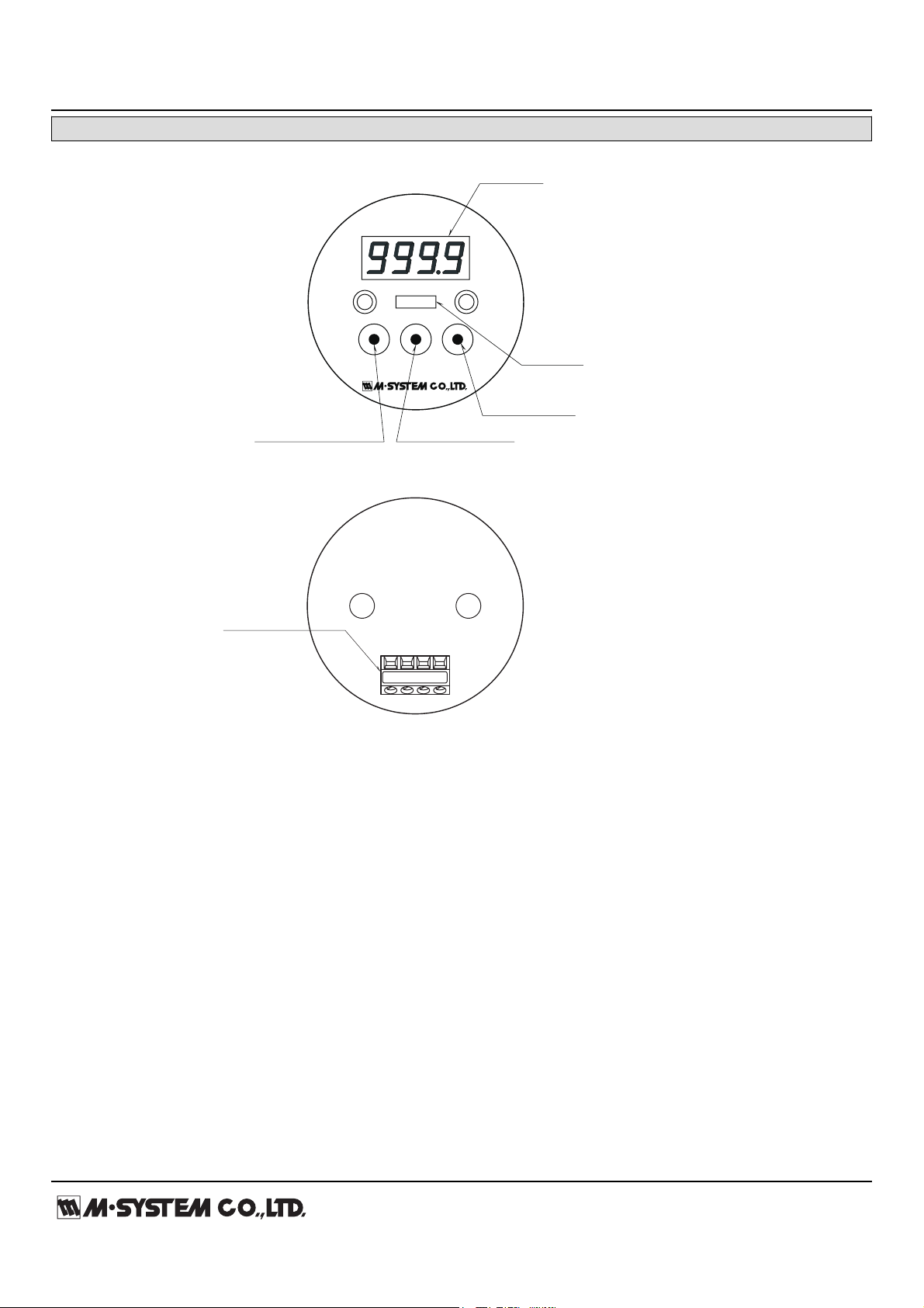
EXTERNAL VIEW (indicator module)
°C
ENTR / ESC BACK / DOWN NEXT / UP
Engineering
Unit
ENTER / ESCAPE Button BACK / DOWN Button
NEXT / UP Button
Data Display
1 2 3 4
Terminal block
■ FRONT VIEW
■ REAR VIEW
Page 5

MODEL: 6DV-B
http://www.m-system.co.jp/ 6DV-B SPECIFICATIONS ES-4220 Rev.14 Page 5/7
DIMENSIONS unit: mm (inch)
4–M8, 12 deep
92 (3.62)
110 (4.33)
70 (2.76)
118
(4.65)
7 (.28)
max.
39
(1.54)
19
(.75)
92 (3.62)
104 (4.09)
14
(.55)
26
(1.02)
MOUNTING BRACKET
(optional)
STOPPING PLUG (TIIS flameproof)
*
CABLE GLAND
*
(TIIS flameproof)
G 1/2
110
(4.33) dia.
39
(1.54)
dia.
19 (.75)
2–G1/2, 1/2NPT,
M20x1.5 or PG13.5
SPACE REQUIRED TO REMOVE COVER
174
(6.85)
114 (4.49)
max. 78 (3.07)
approx. 7 (.28)
110 (4.33)
*Two cable glands and one plug are provided with TIIS flameproof type.
Use them according to the field wiring requirements.
Page 6
MODEL: 6DV-B
http://www.m-system.co.jp/ 6DV-B SPECIFICATIONS ES-4220 Rev.14 Page 6/7
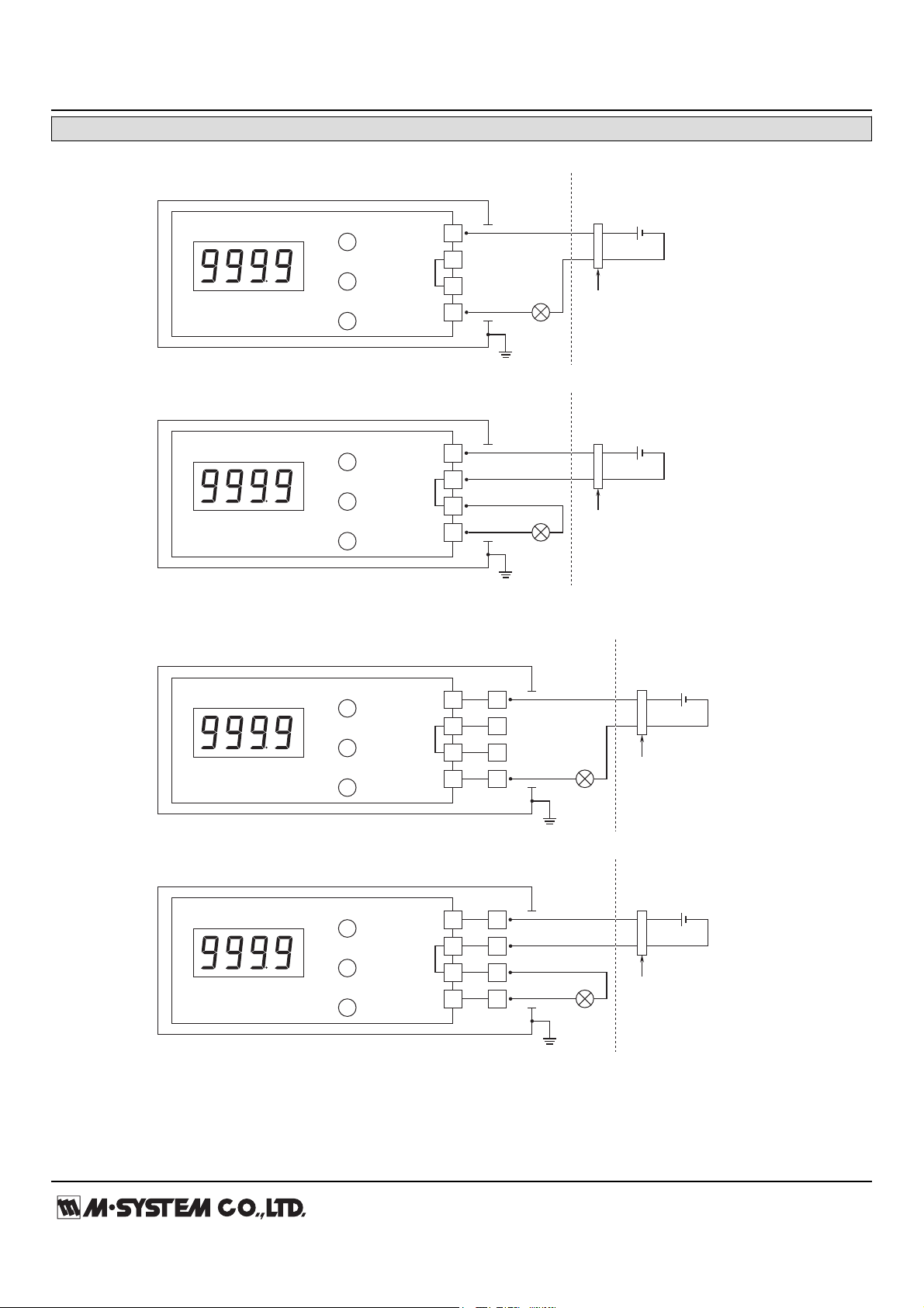
CONNECTION DIAGRAM
ENTR / ESC
BACK / DOWN
NEXT / UP
LED Display
Internal
Bridge
Power Source
1
2
4
3
+
–
ENTR / ESC
BACK / DOWN
NEXT / UP
LED Display
Internal
Bridge
Power Source
1
2
4
3
+
–
■ WITHOUT TERMINAL BLOCK (Euro terminal block at the rear of indicator module)
ENTR / ESC
BACK / DOWN
NEXT / UP
LED Display
Internal
Bridge
1
2
4
3
+
–
ENTR / ESC
BACK / DOWN
NEXT / UP
LED Display
Internal
Bridge
1
2
4
3
9
10
12
11
9
10
12
11
+
–
■ WITH TERMINAL BLOCK
Two-wire
Transmitter
+ –
Two-wire
Transmitter
+ –
*
1
Non-Hazardous
Location
Hazardous Location
Safety Barrier
Power Source
Power Source
Two-wire
Transmitter
+ –
Two-wire
Transmitter
+ –
*
1
Non-Hazardous
Location
Hazardous Location
Safety Barrier
*
1
Non-Hazardous
Location
Hazardous Location
Safety Barrier
*
1
*
3
*
2
Non-Hazardous
Location
Hazardous Location
Safety Barrier
A safety barrier must be installed for the intrinsic safety.
The safety barrier must meet the Ex-data of this unit and must be approved for the hazardous location.
In order to use a two-wire transmitter in the TIIS intrinsically safe circuit, the combination of the 6DV-B
with the transmitter must be re-evaluated and approved by the TIIS.
This connection digram is not applicable for the TIIS intrinsic safety.
*1.
*2.
*3.
Page 7
MODEL: 6DV-B
http://www.m-system.co.jp/ 6DV-B SPECIFICATIONS ES-4220 Rev.14 Page 7/7
Specifications are subject to change without notice.
 Loading...