

Page 1
MODEL: 48NDVD
http://www.m-system.co.jp/ 48NDVD SPECIFICATIONS ES-9439 Rev.10 Page 1/9
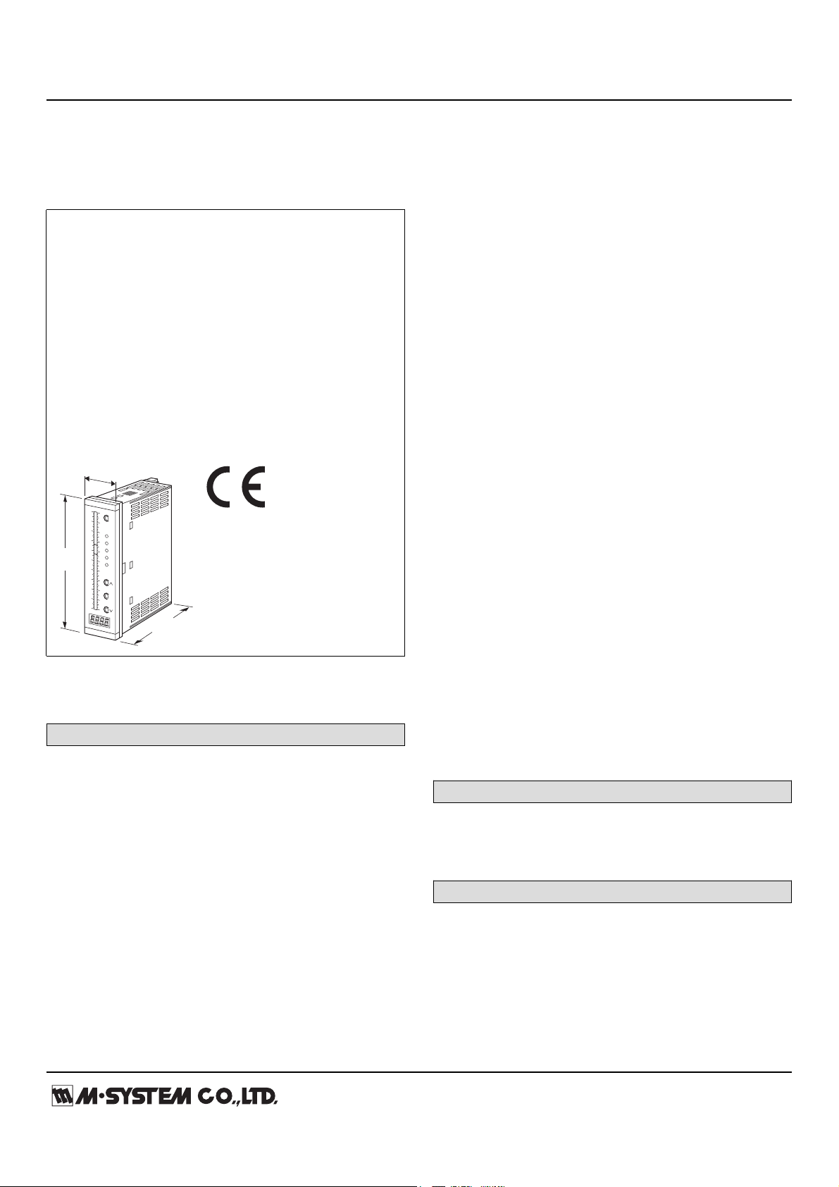
Bargraph Indicators 48N Series
50
40
30
20
10
0
10
20
30
40
50
m
3
/h
%
mA
100
SET
H
S
P
Z
L
90
80
70
60
50
40
30
20
10
0
M
144
(5.67)
36 (1.42)
103
(4.06)
mm (inch)
BARGRAPH INDICATING ALARM
(with 4-digit digital meter; with 2-wire transmitter
excitation)
• Displays a process variable in graphic bargraph
of 101 LED segments in proportion to a 2-wire
transmitter output
• Clear 4-digit digital meter
• 2-wire transmitter excitation
• Usable with a smart transmitter
• Provides max. 4 alarm contact outputs
• Multi-color indicator
• LED brightness adjustment
• IP65 front cover
• Scale plate is easily replaced
• Separable terminal block
[2] BAR LED COLOR
R: Red
Y: Amber
G: Green
B: Blue
1: Multi-color (red, orange and green), Pattern 1
(See ‘External View.’)
2: Multi-color (red, orange and green), Pattern 2
(See ‘External View.’)
INPUT
Current
4 – 20 mA DC (Input resistance 250 Ω)
[3] POWER INPUT
AC Power
M: 85 – 264 V AC (Operational voltage 85 – 264 V, 50/60 Hz
(CE marking not available)
M2: 100 – 240 V AC (Operational voltage range 85 – 264 V, 50/60 Hz)
DC Power
R: 24 V DC
(Operational voltage range 24 V ±15 %, ripple 10 %p-p max.)
[4] OPTIONS (multiple selections)
Standards & Approvals
blank: Without CE
/CE: CE marking
Bezels
blank: Bezels for M-System’s 48 Series panel cutout
/D: Bezels for DIN panel cutout
MODEL: 48NDVD–[1][2]–[3][4]
ORDERING INFORMATION
• Code number: 48NDVD-[1][2]-[3][4]
Specify a code from below for each [1] through [4].
(e.g. 48NDVD-42-R/CE/D/Q)
• Special input range (For codes Z & 0)
• Bargraph scale (e.g. 0 – 100 %) (See ‘Scale Plate.’)
• Digital indicator scale (e.g. 0.0 – 130.0)
• Specify the specification for option code /Q
(e.g. /SET)
[1] ALARM OUTPUT
0: None
2: 2 points
4: 4 points
/F: Bezels for Fuji Electric's PAJ, PAK, PBA panel cutout
Other Options
blank: none
/Q: Option other than the above (specify the specification)
SPECIFICATIONS OF OPTION: Q
EX-FACTORY SETTING
/SET: Preset according to the Ordering Information Sheet
(No. ESU-9436)
BEZEL OPTION
Bezels are used to adapt the 48N Series to an existing panel
cutout. In order to replace M-System’s 48 Series products,
use the one attached to the 48N Series as standard. When
the existing panel is cut according to DIN standard, specify
‘/D’ suffix code.
For a new installation, no bezel is required. Please refer to
‘Mounting Requirement’ and mount the 48N directly.
Ingress protection is invalid when the 48N is mounted with a
bezel, or when multiple modules are stacked side by side.
Page 2

MODEL: 48NDVD
http://www.m-system.co.jp/ 48NDVD SPECIFICATIONS ES-9439 Rev.10 Page 2/9
SPARE PARTS
0 50 100
Input
(%)
L Setpoint H Setpoint
H Output
L Output
• Alarm Suffix Code 2
Alarm Trip Operation Terminal No. in parentheses
(7–8)ON
(12–14)ON
(13–14)ON
(7–9)ON
0 50 100
Input
(%)
L H
HH Output
LL Output
H Output
L Output
HHLL
• Alarm Suffix Code 4
Terminals 7 –Ê 9, 13 – 14 turn on at a loss of power.
Terminals 7 –Ê 9, 13 – 14 turn on at a loss of power.
(7–8)ON
(7–9)ON
(7–10)ON
(11–14)ON
(12–14)ON
(13–14)ON
• Scale plate
GENERAL SPECIFICATIONS
Construction: Panel flush mounting
Degree of protection: IP65; applicable to the front panel for
single unit mounted according to the specified panel cutout
Connection: M3 separable screw terminal (torque 0.6 N·m)
Screw terminal: Nickel-plated steel
Housing material: Flame-resistant resin (black)
Isolation: Input to output to power
Zero adjustment: -10 to +10 % (front)
Span adjustment: 90 to 110 % (front)
Scale plate: Flame resistant resin (white scale & characters
on black base)
H & L alarm output delay: 0 sec. (factory setting;
fieldselectable between 0 and 15 sec. by 1 sec. increments)
Setpoint adjustment
2 points:
H [L setpoint ] to 100 %
L 0 to [H setpoint]
or No alarm trip
4 points:
HH [H setpoint] to 100 %
H [L setpoint] to [HH setpoint]
L [LL setpoint] to [H setpoint]
LL 0 to [L setpoint]
or No alarm trip
Alarm deadband (hysteresis): 1 %
Setting: (Front button)
• Zero and span adjustments
• Alarm setpoint
• Others
(Refer to the instruction manual for details)
Read rate: 10/s
Moving average sample number: 4 (factory setting; field
selectable among 1, 2, 4, 8 or 16)
LED brightness adjustment: 7 levels
■ BARGRAPH
LED: 101-segment LED, 100 mm (3.96”) long, 3.00 mm
(.12”) wide
Display range: 0 to 100 (scaling function not available)
(0 % or 100 % position bar blinks when over range)
Scale: Two different scales available for single bargraph
Characters: Max. 4 characters including decimal point and
negative sign
Divisions: Min. 22, max. 100
Engineering unit: Max. 6 characters
■ DIGITAL DISPLAYS
LED: 7-segment red LED, character 8 mm (.31”) high
Number of digits: 4 digits
Setting range: -1999 to 9999
(Min. 3 significant digits)
Minimum scale value: 100 (3 digits, the decimal point
position disregarded)
Scaled range: The range between -1999 to 9999 and -15 to
+115 % of input span
(The indicator blinks when the input is out of the range)
Decimal point position: 10–1, 10–2, 10–3 or none
Zero indication: Higher-digit zeros are suppressed
Engineering unit: Max. 6 characters on scale plate
SUPPLY OUTPUT
(across the terminals 3 – 4)
Output voltage: 24 – 28 V DC with no load
18 V DC min. at 20 mA
Current rating: ≤ 22 mA DC
• Shortcircuit Protection
Current limited: 30 mA max.
Protected time duration: No limit
INPUT SPECIFICATIONS
■ DC Current: Input resistor incorporated
OUTPUT SPECIFICATIONS
■ Alarm Output: Relay contact
Rated load: 250 V AC @1 A (cos ø = 1)
30 V DC @5 A (resistive load)
Maximum switching voltage: 250 V AC, 220 V DC
Maximum switching power: 380 VA, 150 W
Minimum load: 5 V DC @100 mA
Mechanical life: ≥ 5 × 10⁸ cycles (rate 180 cycles/min.)
Page 3
MODEL: 48NDVD
http://www.m-system.co.jp/ 48NDVD SPECIFICATIONS ES-9439 Rev.10 Page 3/9
INSTALLATION
Power Consumption
•AC:
Approx. 5.5 VA at 100 V with max. load
Approx. 7 VA at 200 V with max. load
Approx. 8 VA at 264 V with max. load
•DC
Approx. 3.5 W at 20.4 V with max. load
Approx. 3.5 W at 24 V with max. load
Approx. 3.5 W at 27.6 V with max. load
Operating temperature: -5 to +55°C (23 to 131°F)
Operating humidity: 30 to 90 %RH (non-condensing)
Mounting: Panel flush mounting
Weight: 300 g (0.66 lb)
PERFORMANCE in percentage of span
Accuracy
Bargraph: ±1 % ±1 digit
Digital indicator: ±0.5 % ±1 digit
Temp. coefficient: ±0.015 % of FS/°C (±0.008 % of FS/°F)
Response time: ≤ 0.5 sec.
(moving average sample number set to 4)
Insulation resistance: ≥ 100 MΩ with 500 V DC
Dielectric strength: 2000 V AC @1 minute (input to output
to power to ground)
STANDARDS & APPROVALS
CE conformity:
EMC Directive (2004/108/EC)
EMI EN 61000-6-4: 2007/A1: 2011
EMS EN 61000-6-2: 2005
Low Voltage Directive (2006/95/EC)
EN 61010-1: 2010
Measurement Category II
Pollution degree 2
Input to output to power – Reinforced insulation (300 V)
Page 4

MODEL: 48NDVD
http://www.m-system.co.jp/ 48NDVD SPECIFICATIONS ES-9439 Rev.10 Page 4/9
SCALE PLATE
■ WHAT MUST BE SPECIFIED WHEN ORDERING
Please specify the bargraph scale range and engineering unit. The overvall scale plate design including the number of
divisions, division line length, character font is determined by M-System.
[Example] : Bargraph range 0 to 300 cm
Bargraph scale range: 0 – 300
Engineering unit for the bargraph: cm
■ TYPES OF DIVISIONS
Five (5) types of divisions are used depending upon the scale span, which determined by the following equation:
Scale Span = (Max. range value – Min. range value) x 10
where n = integer (used to limit the calculated scale span to the minimum of 1.1, below 11.0.)
The number of divisions is automatically determined by the scale span.
• Type 1: 1.1 Scale Span < 1.3
Number of divisions: 22 to 25.9
Scale: Starts at 0, increments by 0.02 / 0.2 / 2 / 20 /
200. Min. and max. values indicated. 4 digits
including negative sign and decimal point.
Division lines: Long, Short, Medium, Short, Long
(4 divisions repeated)
• Type 3: 2.0 Scale Span < 2.6
Number of divisions: 40 to 51.9
Scale: Starts at 0, increments by 0.05 / 0.5 / 5 / 50 /
500. Min. and max. values indicated. 4 digits
including negative sign and decimal point.
Division lines: Long, Short, Medium, Short, Medium,
Short, Medium, Short, Medium, Short, Long
(10 divisions repeated)
Minimum
Divisions
Maximum
Divisions
Bipolar
Scale
10
11
8
6
4
2
0
600
400
200
0
-200
-400
0.2
0
-600
0.4
0.6
0.8
1.0
1.2
1.29
Minimum
Divisions
Maximum
Divisions
Bipolar
Scale
120
100
50
0
-50
-100
-120
0
0
0.5
1
1.5
2
2.59
5
10
15
20
• Type 2: 1.3 Scale Span < 2.0
Number of divisions: 26 to 39.9
Scale: Starts at 0, increments by 0.03 / 0.3 / 3 / 30 /
300. Min. and max. values indicated. 4 digits
including negative sign and decimal point.
Division lines: Long, Short, Medium, Short, Medium,
Short, Long (6 divisions repeated)
n
• Type 4: 2.6 Scale Span < 5.5
Number of divisions: 26 to 54.9
Scale: Starts at 0, increments by 0.05 / 0.5 / 5 / 50 /
500. Min. and max. values indicated. 4 digits
including negative sign and decimal point.
Division lines: Long, Medium, Medium, Medium,
Medium, Long (5 divisions repeated)
Minimum
Divisions
Maximum
Divisions
Bipolar
Scale
0
0.3
0.6
0.9
1.2
1.5
1.8
0.6
0.3
0
-0.3
-0.6
-0.8
0.8
1.99
0
30
60
90
120
130
Minimum
Divisions
Maximum
Divisions
Bipolar
Scale
250
200
150
100
50
0
-50
-100
-150
-200
-250
0 0
0.5
1
1.5
2
2.5
3
3.5
4
4.5
5
5.49
50
100
150
200
250
260
Page 5

MODEL: 48NDVD
http://www.m-system.co.jp/ 48NDVD SPECIFICATIONS ES-9439 Rev.10 Page 5/9
• Type 5: 5.5 Scale Span < 11.0
Number of divisions: 27.5 to 54.9
Scale: Starts at 0, increments by 0.01 / 0.1 / 1 / 10 /
100 / 1000. Min. and max. values indicated.
4 digits including negative sign and decimal
point.
Division lines: Long, Medium, Medium, Medium,
Medium, Long (5 divisions repeated)
300
250
cm
m
3
SET
S
P
Z
L
LL
HH
H
M
200
150
100
50
0
Minimum
Divisions
Maximum
Divisions
Bipolar
Scale
0.5
0.4
0.3
0.2
0.1
0
-0.1
-0.2
-0.3
-0.4
-0.5
0
100
200
300
400
500
550
0
1
2
3
4
5
6
7
8
9
10
10.9
[Example] : Bargraph range 0 to 300 cm (Type 4)
Digital indicator range 0.00 to 6.75 m3
(Type 4)
Left scale range: 0 – 300
Left scale unit (bargraph): cm
Right scale: None
Digital indicator unit: m3
Page 6

MODEL: 48NDVD
http://www.m-system.co.jp/ 48NDVD SPECIFICATIONS ES-9439 Rev.10 Page 6/9
EXTERNAL VIEW
50
40
30
20
10
0
-10
-20
-30
-40
-50
m
3
/h %
mA
100
SET
2
S
P
Z
1
90
80
70
60
50
40
30
20
10
0
SET (ENTER) Button
Color Setpoint 2 Adj. & Function
Span Adj. & Setting
Decimal Point Position, Moving Average,
Brightness Adj.
Zero Adj. & Setting
Color Setpoint 1 Adj. & Function
Setting Up Button, Switcing Detailed Settings
Mode & Setting Selector
Setting Down Button, Switcing Detailed Settings
Digital Indicator
Setpoint 2 Value
Setpoint 1 Value
PV Indicator
M
Setpoint 1 or 2 provided only for the multi-color bar type.
■ ALARM SUFFIX CODE 0: None
• Bar Color Patterns
Pattern 1 (model suffix code 1)
orange orange
green
orange
Input < L L < Input < H H < Input
green
red
H
L
Pattern 2 (model suffix code 2)
orange green
green
red
red
red
H
L
50
40
30
20
10
0
-10
-20
-30
-40
-50
m
3
/h %
mA
100
SET
H
S
P
Z
L
90
80
70
60
50
40
30
20
10
0
SET (ENTER) Button
H Setpoint Adj. & Alarm Function
Span Adj. & Setting
Decimal Point Position, Moving Average,
Brightness Adj.
Zero Adj. & Setting
L Setpoint Adj. & Alarm Function
Setting Up Button, Switcing Detailed Settings
Mode & Setting Selector
Setting Down Button, Switcing Detailed Settings
H Setpoint
L Setpoint
PV Indicator
M
50
40
30
20
10
0
-10
-20
-30
-40
-50
m
3
/h %
mA
100
SET
H
S
P
Z
L
90
80
70
60
50
40
30
20
10
0
SET (ENTER) Button
HH Setpoint Adj. & Alarm Function
H Setpoint Adj. & Alarm Function
Span Adj. & Setting
Decimal Point Position, Moving Average,
Brightness Adj.
Zero Adj. & Setting
L Setpoint Adj. & Alarm Function
LL Setpoint Adj. & Alarm Function
Setting Up Button, Switcing Detailed Settings
Mode & Setting Selector
Setting Down Button, Switcing Detailed Settings
HH Setpoint
H Setpoint
L Setpoint
LL Setpoint
PV Indicator
HH
LL
M
■ ALARM SUFFIX CODE 2: 2 points
Digital Indicator
■ ALARM SUFFIX CODE 4: 4 points
Digital Indicator
Page 7

MODEL: 48NDVD
http://www.m-system.co.jp/ 48NDVD SPECIFICATIONS ES-9439 Rev.10 Page 7/9
DIMENSIONS unit: mm (inch)
75 (2.95)
103 (4.06)
10 (.39) 18
(.71)
1
2
3
4
5
6
7
8
9
10
11
12
13
14
15
16
16–M3 SCREW
TERMINALS
2–M3 SCREWS
144 (5.67)
137.5 (5.41)
4
*
1
(.16)
36 (1.42) 31 (1.22)
100 (3.94)
Rounded corners for the option /D
■ OPTION /D BEZEL
*
3
*1. Space required when replacing the scale plate.
*2. Used for the existing panel cutout of M-System 48 Series (38 × 139.5 mm).
*3. Used for the existing DIN panel cutout (33 × 138 mm)
*4. Used for the existing panel cutout of Fuji Electric PAJ, PAK, PBA (44 × 138 mm), etc.
■ STANDARD BEZEL
*
2
10.4
(.41)
7.5
(.30)
3.9
(.15)
136.5 (5.37)
144 (5.67)
11.4
(.45)
7.5
(.30)
4.9
(.19)
136.5 (5.37)
144 (5.67)
8.5
(.33)
10.4
(.41)
7.5
(.30)
136.5 (5.37)
144 (5.67)
■ OPTION /F BEZEL
*
4
Page 8

MODEL: 48NDVD
http://www.m-system.co.jp/ 48NDVD SPECIFICATIONS ES-9439 Rev.10 Page 8/9
PANEL CUTOUT unit: mm
138
+1
–0
31.5
Note 1. Observe at the minimum of 3 cm
above and below the units for
heat dissipation.
Note 2. No bezel is needed when
the panel is cut according to
the left drawings.
Panel thickness: 1.6 – 8.0 mm
■ SINGLE MOUNTING (ingress protection)
138
+1
–0
L
Panel thickness: 1.6 – 8.0 mm
L = {31.5 + 36 × (N –Ê 1)}
(N : number of units)
+1
–0
■ CLUSTERED MOUNTING (no ingress protection)
+1
–0
12
13
14
15
16
POWER
U(+)
V(–)
LLa
11
La
LLb
Lc, LLc
LOAD
Inductive
Load (Coil)
Varistor or
CR Circuit
• DC Powered
LOAD
Inductive
Load (Coil)
Diode, Varistor
or CR Circuit
■ Relay Protection
• AC Powered
8
9
10
HHa
7
Hc, HHc
HHb
Ha
HH OUTPUT
H OUTPUT
LL OUTPUT
L OUTPUT
■ ALARM SUFFIX CODE 4: 4 points
Low Drift
Amplifier
Display /
Setting
Digital
Computation
12
13
14
15
16
POWER
U (+)
V (–)
La
Lb
Lc
8
9
Ha
7
Hc
Hb
H OUTPUT
L OUTPUT
■ ALARM SUFFIX CODE 2: 2 points
5
6
15
16
POWER
U (+)
V (–)
11
10
■ ALARM SUFFIX CODE 0: None
Low Drift
Amplifier
Display /
Setting
Digital
Computation
Digital
Computation
12
13
14
8
9
7
1
2
3
4
5
6
1
2
3
4
Ry
Ry
Ry
Ry
Ry
Ry
*
*
*Input shunt resistor incorporated for current input.
*Input shunt resistor incorporated for current input.
–
+
2-WIRE
XMTR
+
–
–
+
2-WIRE
XMTR
+
–
■ 4 – 20mA Input without Excitation
250Ω
+
–
INPUT
+
–
3
2
4
1
–
+
MONITOR
1 – 5V DC
V
–
+
MONITOR
1 – 5V DC
V
SCHEMATIC CIRCUITRY & CONNECTION DIAGRAM
Page 9

MODEL: 48NDVD
http://www.m-system.co.jp/ 48NDVD SPECIFICATIONS ES-9439 Rev.10 Page 9/9
Specifications are subject to change without notice.
 Loading...