

Page 1
5-2-55, Minamitsumori, Nishinari-ku, Osaka 557-0063 JAPAN
Phone: +81(6)6659-8201 Fax: +81(6)6659-8510 E-mail: info@m-system.co.jp
EM-9440 Rev.6 P. 1 / 8
INSTRUCTION MANUAL
BARGRAPH INDICATING ALARM
(with 2-wire transmitter excitation)
MODEL
48NAVD
BEFORE USE ....
Thank you for choosing M-System. Before use, please check
contents of the package you received as outlined below.
If you have any problems or questions with the product,
please contact M-System’s Sales Office or representatives.
■ PACKAGE INCLUDES:
Bargraph indicator (incl. scale plate) .................................(1)
Mounting bracket ................................................................(2)
Bezel*
1
..................................................................................(2)
Watertight packing .............................................................(1)
*1. The size of included bezel differs depending on option code.
■ MODEL NO.
Confirm Model No. marking on the product to be exactly
what you ordered.
■ INSTRUCTION MANUAL
This manual describes necessary points of caution when
you use this product, including installation, connection and
basic maintenance procedures.
POINTS OF CAUTION
■ CONFORMITY WITH EU DIRECTIVES
•This equipment is suitable for Pollution Degree 2 and Installation Category II (transient voltage 2500V). Reinforced insulation (signal input to output to power input:
300V) is maintained. Prior to installation, check that the
insulation class of this unit satisfies the system requirements.
•The equipment must be mounted on a panel surface.
Once mounted on a panel, take appropriate precautions
to prevent operators to be exposed to the terminal block.
•Altitude up to 2000 meters.
•Insert a noise filter for the power source connected to the
unit. TDK-Lambda Noise Filter Model RSAN-2006 or
equivalent is recommended.
•The equipment must be installed such that appropriate
clearance and creepage distances are maintained to conform to CE requirements. Failure to observe these requirements may invalidate the CE conformance.
•The actual installation environments such as panel configurations, connected devices, connected wires, may affect
the protection level of this unit when it is integrated in a
panel system. The user may have to review the CE requirements in regard to the whole system and employ additional protective measures to ensure the CE conformity.
•In order to enable the operator to turn off the power input immediately, install a switch or a circuit breaker according to the relevant requirements in IEC 60947-2 and
properly indicate it.
■ POWER INPUT RATING & OPERATIONAL RANGE
•Locate the power input rating marked on the product and
confirm its operational range as indicated below:
100 – 240V and 85 – 264V AC rating: 85 – 264V, 50/60 Hz,
approx. 5.5 – 8.5VA
24V DC rating: 24V ±15%, approx. 3 – 3.5W
■ GENERAL PRECAUTIONS
•Before you remove the unit or mount it, turn off the power
supply and input signal for safety.
•Be sure to put the terminal cover on while the power is
supplied.
■ ENVIRONMENT
•Indoor use.
•If the unit’s environmental protection is compromised
(e.g. when multiple units are to be mounted side by side)
when heavy dust or metal particles are present in the air,
install them inside an enclosure with a proper ventilation.
•Do not install the unit where it is subjected to continuous
vibration. Do not subject the unit to physical impact.
•Environmental temperature must be within -10 to +55°C
(14 to 131°F) with relative humidity within 30 to 90% RH
in order to ensure adequate life span and operation.
■ REQUIREMENTS TO ENSURE IP65
•Observe the designated panel cutout size (31.5 × 138 mm).
•Single mounting only. IP65 is not ensured when the units
are clustered side by side.
•The watertight packing included in the product package
must be placed behind the front cover.
•The mounting bracket must be fastened tightly until they
hit the panel.
•Confirm visually that the packing is not contorted or excessively run off the edge after installation.
■ WIRING
•Do not install cables close to noise sources (relay drive
cable, high frequency line, etc.).
•Do not bind these cables together with those in which
noises are present. Do not install them in the same duct.
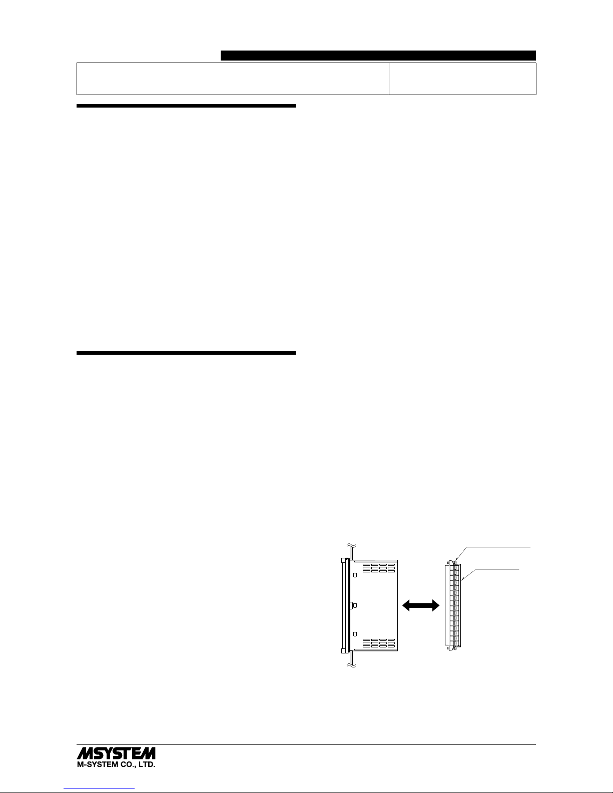
■ TERMINAL BLOCK
•The terminal block is separable in two pieces. Loosen two
screws on top and bottom of the terminal block to separate.
•Be sure to turn off the power supply, input signal and
power supply to the output relays before separating the
terminal block.
Terminal Block
Separable
Terminal Block Screw
(top & bottom)
■ AND ....
•The unit is designed to function as soon as power is supplied, however, a warm up for 10 minutes is required for
satisfying complete performance described in the data
sheet.
Page 2
48NAVD
5-2-55, Minamitsumori, Nishinari-ku, Osaka 557-0063 JAPAN
Phone: +81(6)6659-8201 Fax: +81(6)6659-8510 E-mail: info@m-system.co.jp
EM-9440 Rev.6 P. 2 / 8
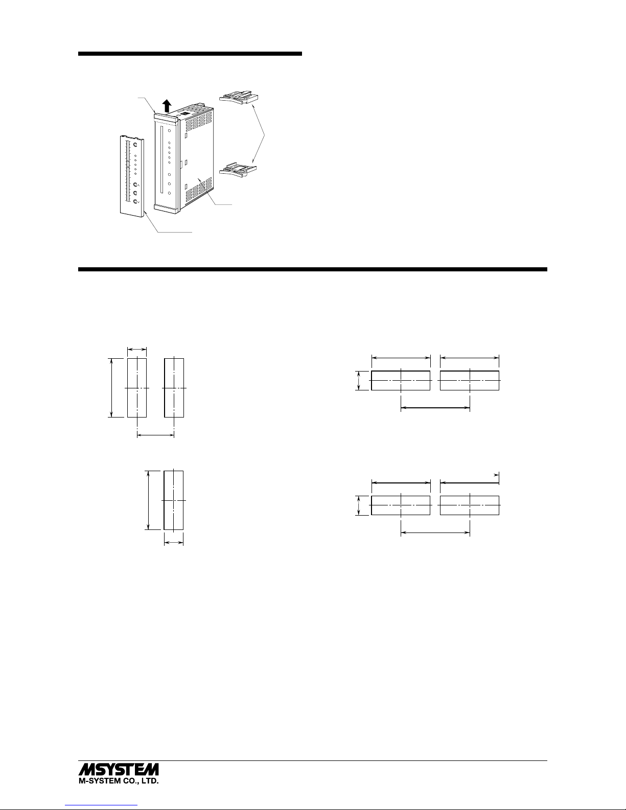
COMPONENT IDENTIFICATION
50
40
30
20
10
0
10
20
30
40
50
m
3
/h %
100
SET
H
S
•
Z
L
90
80
70
60
50
40
30
20
10
0
M
Brackets
Body
A
Scale Plate
Pull up the part ‘A’ when replacing the scale plate.
INSTALLATION
■ PANEL CUTOUT unit: mm
138
+1
–0
164 min.
Note 1: Observe at the minimum of 3 cm above and below the units for heat dissipation.
Note 2: No bezel is needed when the panel is cut according to the above drawings.
Panel thickness: 1.6 – 8.0 mm
Panel thickness: 1.6 – 8.0 mm
• Vertical Mounting • Horizontal Mounting
■ SINGLE MOUNTING (Conform to degree of protection IP65)
138
+1
–0
138
+1
–0
L
138
+1
–0
164 min.
L
Panel thickness: 1.6 – 8.0 mm
L = {31.5 + 36 × (N –1)}
(N : number of units)
Panel thickness: 1.6 – 8.0 mm
L = {31.5 + 36 × (N –1)}
(N : number of units)
+1
–0
+1
–0
• Vertical Mounting • Horizontal Mounting
■ CLUSTERED MOUNTING (Not conform to degree of protection IP65)
138
+1
–0
31.5
+1
–0
138
+1
–0
61.5 min.
31.5
+1
–0
Page 3
48NAVD
5-2-55, Minamitsumori, Nishinari-ku, Osaka 557-0063 JAPAN
Phone: +81(6)6659-8201 Fax: +81(6)6659-8510 E-mail: info@m-system.co.jp
EM-9440 Rev.6 P. 3 / 8
■ USING BEZELS
Bezels are used when the unit needs to be adapted to an existing panel cutout. It is not required when the panel cutout
size is as specified in the unit’s data sheet (31.5 × 138 mm).
Three types of bezels are selectable when ordering.
Standard type: Fits into M-System’s 48 Series’ panel
cutout (38 × 139.5 mm)
Option /D type: Fits into DIN panel cutout
(33 × 138 mm)
Option /F type: Fits into Fuji Electric PAJ, PAK, PBA,
etc, panel cutout (44 × 138 mm)
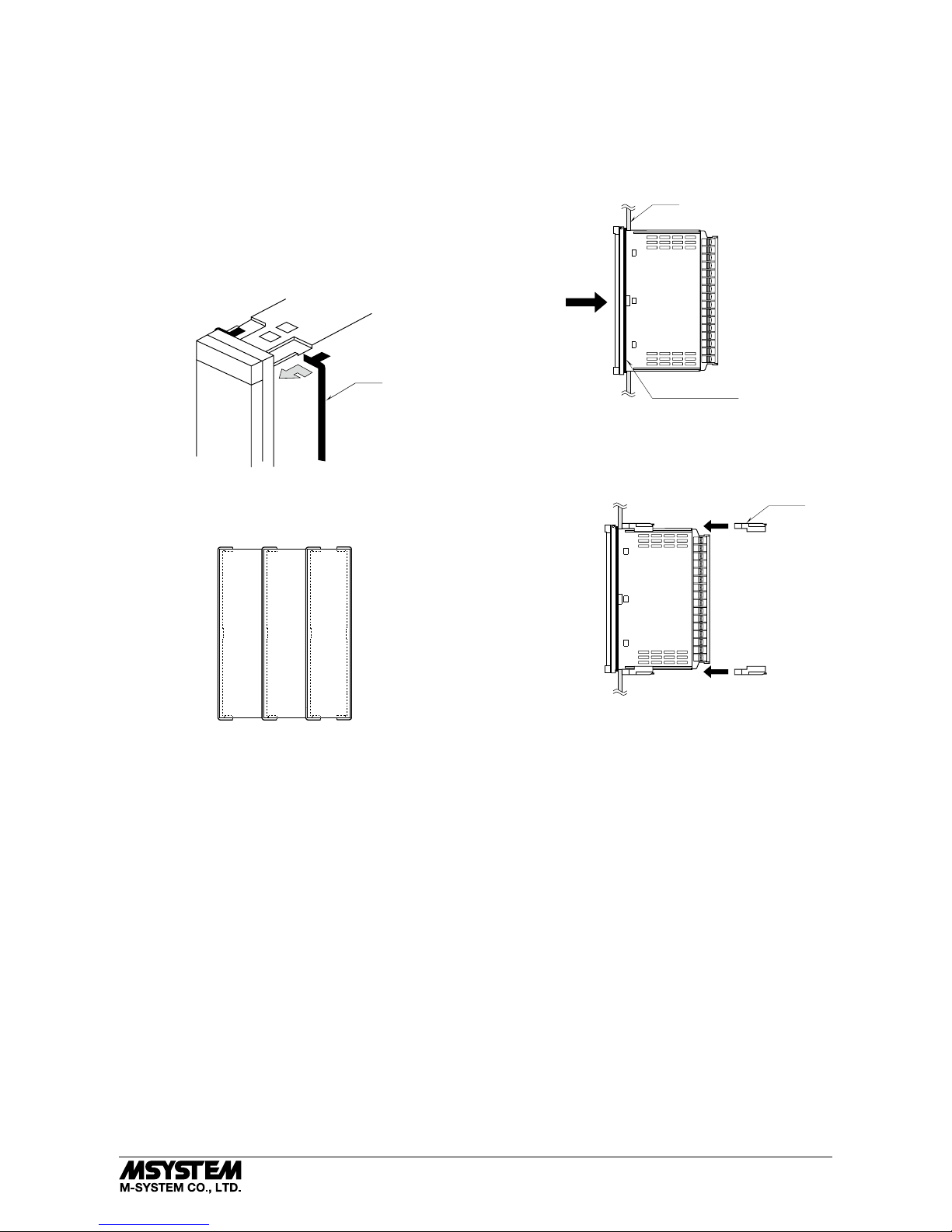
Slide the top and bottom parts of the bezel into the back of
the front cover as shown below.
Bezel
When multiple units are to be clustered side by side, insert
one bezel between two units as shown below.
• When mounting two or more indicators side by side:
■ HOW TO MOUNT THE UNIT ON A PANEL
1) Insert the unit into the panel cutout. The watertight
packing must be in place to hold the unit. Do not remove
it even when the protection is not required.
The IP65 front cover protection is effective only with sin-
gle mounting, with the designated cutout size (31.5 ×138
mm).
Panel
Watertight Packing
2)
Push the mounting brackets into the grooves on top and bottom of the rear module, until they hit the panel’s rear side.
Leave at least 3 centimeters both above and below the
unit for ventilation.
Bracket
Page 4

48NAVD
5-2-55, Minamitsumori, Nishinari-ku, Osaka 557-0063 JAPAN
Phone: +81(6)6659-8201 Fax: +81(6)6659-8510 E-mail: info@m-system.co.jp
EM-9440 Rev.6 P. 4 / 8
TERMINAL CONNECTIONS
Connect the unit as in the diagram below or refer to the connection diagram on the side of the unit.
■ EXTERNAL DIMENSIONS unit: mm (inch)
75 (2.95)
103 (4.06)
10 (.39) 18
(.71)
1
2
3
4
5
6
7
8
9
10
11
12
13
14
15
16
16–M3 SCREW
TERMINALS
Rounded corners for the option /D
2–M3 SCREWS
144 (5.67)
137.5 (5.41)
4
*
1
(.16)
36 (1.42)
■ OPTION /D BEZEL
*
3
*1. Space required when replacing the scale plate.
*2. Used for the existing panel cutout of M-System 48 Series (38
× 139.5 mm).
*3. Used for the existing DIN panel cutout (33
× 138 mm)
*4. Used for the existing panel cutout of Fuji Electric PAJ, PAK, PBA (44
× 138 mm), etc.
■ STANDARD BEZEL
*
2
10.4
(.41)
7.5
(.30)
3.9
(.15)
31 (1.22)
136.5 (5.37)
144 (5.67)
100 (3.94)
11.4
(.45)
7.5
(.30)
4.9
(.19)
136.5 (5.37)
144 (5.67)
8.5
(.33)
10.4
(.41)
7.5
(.30)
136.5 (5.37)
144 (5.67)
■ OPTION /F BEZEL
*
4
Page 5

48NAVD
5-2-55, Minamitsumori, Nishinari-ku, Osaka 557-0063 JAPAN
Phone: +81(6)6659-8201 Fax: +81(6)6659-8510 E-mail: info@m-system.co.jp
EM-9440 Rev.6 P. 5 / 8
■ CONNECTION DIAGRAM
U
12
13
14
15
16
12
13
14
15
16
LLa
11
La
LLb
Lc, LLc
LOAD
Inductive
Load (Coil)
Varistor or
CR Circuit
• DC Powered
LOAD
Inductive
Load (Coil)
Diode, Varistor or
CR Circuit
■ Relay Protection
• AC Powered
7
8
9
8
9
10
HHa
7
Hc, HHc
HHb
Ha
HH OUTPUT
H OUTPUT
LL OUTPUT
L OUTPUT
■ ALARM OUTPUT CODE 2: 2 points
■ ALARM OUTPUT CODE 4: 4 points
–
+
–
+
2-WIRE
XMTR
+
–
MONITOR
1 – 5V DC
V
–
+
–
+
2-WIRE
XMTR
+
–
MONITOR
1 – 5V DC
V
■ 4 – 20mA Input without Excitation
+
–
INPUT
+
–
3
2
4
1
250Ω
U(+)
V(–)
POWER
U(+)
V(–)
La
Lb
Lc
Hc
Ha
Hb
H OUTPUT
L OUTPUT
POWER
1
2
3
4
1
2
3
4
WIRING INSTRUCTIONS
■ SCREW TERMINAL
Torque: 0.6 N·m
■ SOLDERLESS TERMINAL
Refer to the drawing below for recommended ring tongue
terminal size. Spade tongue type is also applicable.
Applicable wire size: 0.25 to 1.65 mm2 (AWG 22 to 16)
Recommended manufacturer: Japan Solderless Terminal
MFG.Co.Ltd, Nichifu Co.,ltd
6 (.24) max
3.3 (.13) max
mm (inch)
Page 6

48NAVD
5-2-55, Minamitsumori, Nishinari-ku, Osaka 557-0063 JAPAN
Phone: +81(6)6659-8201 Fax: +81(6)6659-8510 E-mail: info@m-system.co.jp
EM-9440 Rev.6 P. 6 / 8
FRONT PANEL CONFIGURATION
■ ALARM OUTPUT CODE 2: 2 points
■ ALARM OUTPUT CODE 4: 4 points
• Bar Color Patterns
Pattern 1 (Bar LED color code 1)
orange orange
green
orange
Input < LL < Input < H H < Input
green
red
H
L
Pattern 2 (Bar LED color code 2)
orange green
green
red
red
red
H
L
50
40
30
20
10
0
-10
-20
-30
-40
-50
m
3
/h %
100
SET
H
S
•
Z
L
90
80
70
60
50
40
30
20
10
0
SET (ENTER) Button
H Setpoint Adj. & Trip Indicator (red)
Span Adj. (amber)
Power Saving Mode Indicator (amber)
Zero Adj. (amber)
L Setpoint Adj. & Trip Indicator (green)
UP Button
Mode Selector
DOWN Button
H Setpoint
L Setpoint
PV Indicator
M
50403020100-10-20-30-40-50
m
3
/h
%
100
SET
LZ
•
S
9080706050403020100
H
M
• Vertical Mounting • Horizontal Mounting
50
40
30
20
10
0
-10
-20
-30
-40
-50
m
3
/h %
100
SET
H
S
•
Z
L
90
80
70
60
50
40
30
20
10
0
SET (ENTER) Button
HH Setpoint Adj. & Trip Indicator (red)
H Setpoint Adj. & Trip Indicator (red)
Span Adj. (amber)
Power Saving Mode Indicator (amber)
Zero Adj. (amber)
L Setpoint Adj. & Trip Indicator (green)
LL Setpoint Adj. & Trip Indicator (green)
UP Button
Mode Selector
DOWN Button
HH Setpoint
H Setpoint
L Setpoint
LL Setpoint
PV Indicator
HH
LL
M
50403020100-10-20-30-40-50
m
3
/h
%
100
SET
LL LZ
•
S
9080706050403020100
HHH
M
• Vertical Mounting • Horizontal Mounting
Page 7

48NAVD
5-2-55, Minamitsumori, Nishinari-ku, Osaka 557-0063 JAPAN
Phone: +81(6)6659-8201 Fax: +81(6)6659-8510 E-mail: info@m-system.co.jp
EM-9440 Rev.6 P. 7 / 8
ADJUSTMENT PROCEDURE
L SET
L
M
Increase / Decrease
L Setpoint
Complete
LL SET
LL
M
Increase / Decrease
*2 LL Setpoint
Complete
H SET
H
M
Increase / Decrease
H Setpoint
Complete
HH SET
HH
M
Increase / Decrease
*2 HH Setpoint
Complete
LED OFF
LED OFF
LED BlinkingMode Selector
*
1
UP / DOWN Button
LED BlinkingMode Selector
*
1
■ ZERO ADJUSTMENT: Apply 0% input signal before adjustment.
Z SET
Z
M
Zero Adjustment
Complete
LED OFF
LED BlinkingMode Selector
*
1
S SET
S
M
Span Adjustment
Complete
■ SPAN ADJUSTMENT: Apply 100% input signal before adjustment.
■ ALARM SETTING: Proceed after the zero / span adjustments.
*1. Keep pressing at least for 3 seconds to activate Mode Selector M. Press briefly for second and more times within 1 minute after it has been activated.
*2. HH or LL setpoints are not provided for the 48NAVD-2.
Note: Each setting sequence is complete only when SET button is pressed. Once set, parameters are not lost even after the power is removed, except
for the power saving mode. The power saving mode is automatically cancelled when the power is reset.
• SET
•
M
Indicator OFF
Complete
• SET
•
M
Indicator ON
Complete
LED ON
LED OFF
LED BlinkingMode Selector
*
1
■ POWER SAVING MODE
Page 8

48NAVD
5-2-55, Minamitsumori, Nishinari-ku, Osaka 557-0063 JAPAN
Phone: +81(6)6659-8201 Fax: +81(6)6659-8510 E-mail: info@m-system.co.jp
EM-9440 Rev.6 P. 8 / 8
■ ZERO ADJUSTMENT
1) Apply 0% input signal.
2) Hold down [M] for 3 seconds* and push [M] to choose [Z].
3) Press [SET], and the bargraph shows 0%.
■ SPAN ADJUSTMENT
1) Apply 100% input signal.
2) Hold down [M] for 3 seconds* and push [M] to choose [S].
3) Press [SET], and the bargraph shows 100%.
■ ALARM SETPOINT ADJUSTMENTS
•48NAVD-2: H [Lsetpoint]to100%
L 0% to [H setpoint]
No alarm trip is selectable
•48NAVD-4: HH [Hsetpoint]to100%
H [L setpoint] to [HH setpoint]
L [LL setpoint] to [H setpoint]
LL 0% to [L setpoint]
No alarm trip is selectable
• How to Set LL (or L, H, HH) Setpoints
1) Hold down [M] for 3 seconds* and push [M] to choose
[LL].
2) Press [UP] or [DOWN] buttons until the indicator comes
to the desired position, and press [SET].
(Same procedure for L, H, HH setpoints)
• How to Cancel HH and H Alarms
1) Press [UP] or [DOWN] buttons until the indicator comes
to the upper limit, and press [SET].
HH indicator must be set before H as the H setpoint can-
not go above the HH setpoint.
• How to Cancel LL and L Alarms
1) Press [UP] or [DOWN] buttons until the indicator comes
to the lower limit, and press [SET].
LL indicator must be set before L as the L setpoint can-
not go below the LL setpoint.
* The [M] button remain activated for 1 minute after it
has been used to choose a indicator LED (programming
mode). During this period, pressing the [M] button briefly
is enough to choose another indicator. After 1 minute, it
turns to deactivated state.
CALIBRATION PROCEDURE
This unit is calibrated at the factory to meet the ordered
specifications, therefore you usually do not need any calibration.
For matching the indication to a receiving instrument or in
case of regular calibration, adjust the output as explained
in the following.
■ HOW TO CALIBRATE THE OUTPUT INDICATION
Use a signal source and measuring instruments of sufficient
accuracy level. Turn the power supply on and warm up for
more than 10 minutes.
1) ZERO: Apply 0% input and adjust bargraph to 0% following the procedure explained in “ADJUSTMENT PROCEDURE.”
2) SPAN: Apply 100% input and adjust bargraph to 100%
following the same procedure.
3) Check ZERO adjustment again with 0% input.
4) When ZERO value is changed, repeat the above procedure 1) – 3).
MAINTENANCE
Regular checking procedure is explained below:
■ CHECKING
Warm up the unit for at least 10 minutes. Apply 0%, 25%,
50%, 75% and 100% input signal. Check that the bargraph
for the respective input signal remains within accuracy described in the data sheet. When the bargraph is out of tolerance, recalibrate the unit according to the “CALIBRATION
PROCEDURE” explained earlier.
LIGHTNING SURGE PROTECTION
M-System offers a series of lightning surge protectors for
protection against induced lightning surges. Please contact
M-System to choose appropriate models.
 Loading...