

M-system 47LV Specifications
MODEL: 47LV
http://www.m-system.co.jp/ 47LV SPECIFICATIONS ES-9502 Rev.12 Page 1/7
Digital Panel Meters 47 Series
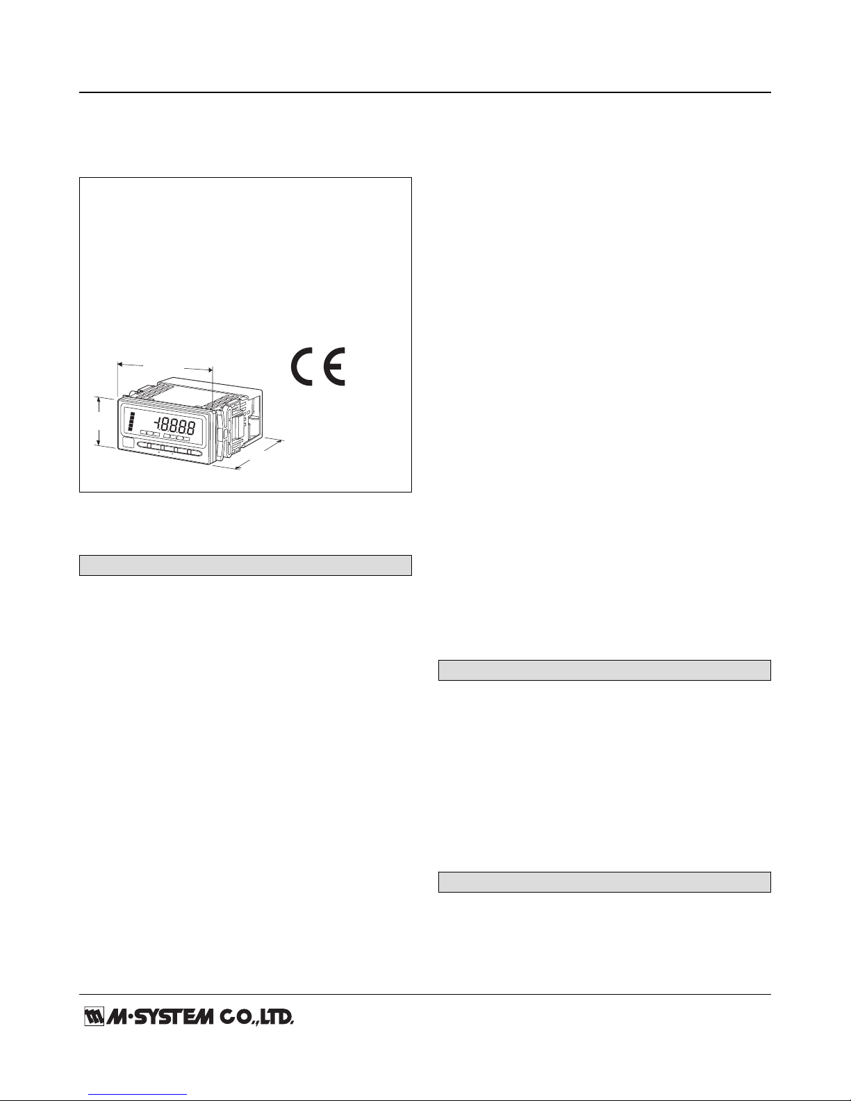
DC INPUT DIGITAL PANEL METER
(4 ½ digit, LED display type)
Functions & Features
• 4 ½ digit DC input digital panel meter
• 1/8 DIN size
• Moving average function to suppress the display flickering
• Scaling, forced zero, low-end cutout
• Max. and Min. value display
• Safety terminal cover tethered to the device with a strap
• IP66 front panel
• Separable terminal block
Alarm/
S
ca
le/
Ma
x
/M
in
S
h
if
t
U
p
Zro
Spn
D/P
Tch
Fnc
Min Max
HH
H
P
L
L
L
48
(1.89)
mm (inch)
96 (3.78)
98.5 (3.88)
MODEL: 47LV-[1][2][3][4]-[5][6]
ORDERING INFORMATION
• Code number: 47LV-1[1][2][3][4]-[5][6]
Specify a code from below for each [1] through [6].
(e.g. 47LV-101G-M2/Q)
• Specify the specification for option code /Q
(e.g. /C01/S01/SET)
[1] INPUT
1: ±10 V, ±5 V, 0 – 5 V, 1 – 5 V
0 – 20 mA, 4 – 20 mA
2: ±1 V, ±100 mV, ±10 mV, ±1 mA
3: ±200 V, ±100 mA
4: ±100 μA (CE not available)
5: ±2 A, ±1 A (CE not available)
6: ±700 V (CE not available)
[2] DC OUTPUT
0: Without
Current
A: 4 – 20 mA DC (Load resistance 550 Ω max.)
D: 0 – 20 mA DC (Load resistance 550 Ω max.)
Voltage
3: 0 – 1 V DC (Load resistance 1000 Ω min.)
(CE not available)
4: 0 – 10 V DC (Load resistance 10 kΩ min.)
5: 0 – 5 V DC (Load resistance 5000 Ω min.)
6: 1 – 5 V DC (Load resistance 5000 Ω min.)
4W: -10 – +10 V DC (Load resistance 10 kΩ min.)
[3] ALARM OUTPUT
0: None
1: N.O. relay contact, 4 points
2: SPDT relay contact, 2 points
[4] DISPLAY COLOR
R: Red
YR: Orange
G: Green
BG: Bluegreen
B: Blue
W: White
[5] POWER INPUT
AC Power
M2: 100 – 240 V AC (Operational voltage range 85 – 264 V, 50/60 Hz)
DC Power
R: 24 V DC
(Operational voltage range 24 V ±10 %, ripple 10 %p-p max.)
P: 110 V DC
(Operational voltage range 85 – 150 V, ripple 10 %p-p max.)
[6] OPTIONS
blank: none
/Q: With options (specify the specification)
SPECIFICATIONS OF OPTION: Q (multiple selections)
COATING (For the detail, refer to M-System's web site.)
Moving parts and indicators are not coated.
/C01: Silicone coating
/C02: Polyurethane coating
/C03: Rubber coating
TERMINAL SCREW MATERIAL
/S01: Stainless steel
EX-FACTORY SETTING
/SET: Preset according to the Ordering Information Sheet
(No. ESU-9502)
GENERAL SPECIFICATIONS
Construction: Panel flush mounting
Degree of protection: IP66; applicable to the front of the
panel meter mounted according to the specified panel
cutout
Connection: M3 separable screw terminal (torque 0.6 N·m)
Screw terminal: Nickel-plated steel (standard) or stainless
MODEL: 47LV
http://www.m-system.co.jp/ 47LV SPECIFICATIONS ES-9502 Rev.12 Page 2/7
steel
Housing material: Flame-resistant resin (gray)
Isolation: Input to DC output to HH output or H output to
L output or LL output to power
Setting: (Front button)
• Scaled range
• Input type
• Alarm setpoint
• Hysteresis (deadband)
• Moving average
• Others
(Refer to the instruction manual for details)
Read rate: 40 times/sec. (25 msec.)
Averaging: None or moving average
Lockout setting: Prohibiting certain operations; protecting
settings
DISPLAY
Display: 16 mm (.63) high, 4 ½ digits, 7-segment LED
Display range: -19999 to 19999
Decimal point position: 10–1, 10–2, 10–3, 10–4 or none
Zero indication: Higher-digit zeros are suppressed.
Over-range indication: ‘-19999’ or ‘19999’ blinking for
display values out of the display range.
‘S.ERR’ and ‘Min’ or ‘Max’ blinking when the input signal is
out of the usable range.
Alarm status indication
LL indicator: Green LED turns on when the LL alarm is
tripped.
L indicator: Green LED turns on when the L alarm is
tripped.
H indicator: Red LED turns on when the H alarm is tripped.
HH indicator: Red LED turns on when the HH alarm is
tripped.
P indicator: Amber LED turns on when none of the other
alarms is tripped.
Only ‘P’ turns on with no-alarm-output type. ‘LL’ or ‘HH’
does not turn on with dual-alarm-output type.
All setpoints can be independently set either for Hi or Lo
alarm trip.
Function indicators:
Zro, Spn, D/P, Tch, Fnc, Min, Max
Display mode status and operation status, amber ON or
blink
Engineering unit indication: Sticker label attached
DC, AC, mV, V, kV, μA, mA, A, kA, mW, W,
kW, var, kvar, Mvar, VA, Hz, Ω, kΩ, MΩ,
cm, mm, m, m/sec, mm/min, cm/min, m/min,
m/h, m/s2, inch, ℓ, ℓ/s, ℓ/min, ℓ/h, m3, m3/sec,
m3/min, m3/h, Nm3/h, N·m, N/m2, g, kg, kg/h,
N, kN, Pa, kPa, MPa, t, t/h, ℃, °F, %RH, J,
kJ, MJ, rpm, sec, min, pH, %, ppm, etc.
INPUT SPECIFICATIONS
Default setting
Input code 1: Measuring range ±10 V
Input code 2: Measuring range ±1 V
Input code 3: Measuring range ±200 V
Input code 4: Measuring range ±100 μA
Input code 5: Measuring range ±2 A
Input code 6: Measuring range ±700 V
Overload capacity
Input code 5: ±3 A for 10 sec., ±2.4 A continuous
Input code 6: ±1000 V for 10 sec., ±840 V continuous
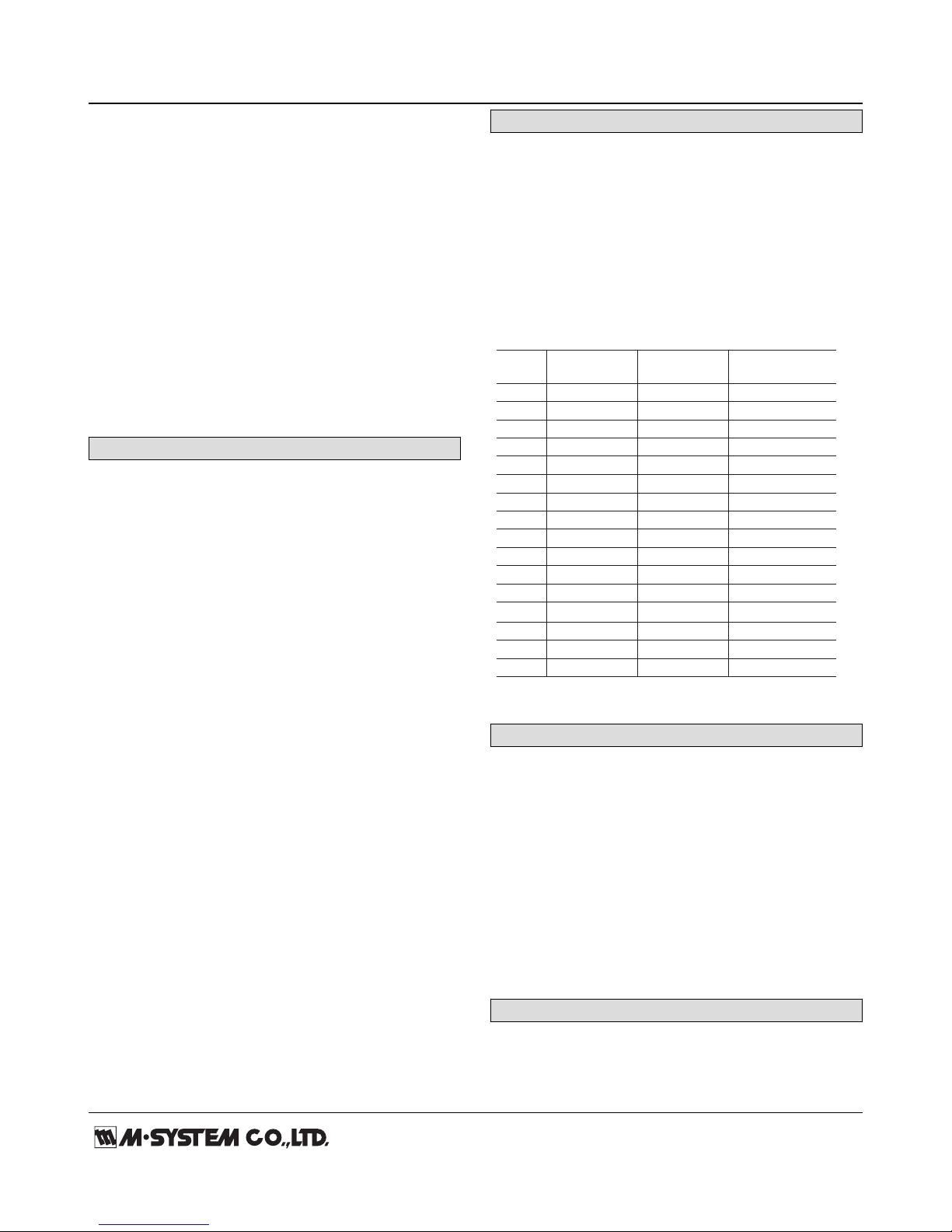
■ DC INPUT
TYPE MEASURING
OPERATIONAL
INPUT
IND RANGE RANGE IMPEDANCE
V10 ±10V -11 – +11V 1MΩ minimum
V5 ±5V -5.5 – +5.5V 1MΩ minimum
V0-5 0 – 5V -0.3 – +5.3V 1MΩ minimum
V1-5 1 – 5V 0.7 – 5.3V 1MΩ minimum
A0-2 0 – 20mA -2 – +22mA approx. 10Ω
A4-2 4 – 20mA 2 – 22mA approx. 10Ω
V1 -1.1 – +1.1V 1MΩ minimum
V01 ±100mV -110 – +110mV 1MΩ minimum
V001 ±10mV -11 – +11mV 1MΩ minimum
A1 ±1mA -1.1 – +1.1mA approx. 100Ω
V200 ±200V -220 – +220V 1MΩ minimum
A100 ±100mA -110 – +110mA approx. 10Ω
±1V
A01 ±100μA -110 – +110μA approx. 1kΩ
A2-2 ±2A -2.2 – +2.2A approx. 0.1Ω
A1-1 ±1A -1.1 – +1.1A approx. 0.1Ω
V700 ±700V -770 – +770V 1MΩ minimum
OUTPUT SPECIFICATIONS
■ DC Output
• DC Current
Operational range: -5 – +105 %
• DC Voltage
Operational range: -5 – +105 %
■ Alarm Output: Relay contact
Rated load: 250 V AC @ 3 A (cos ø = 1)
30 V DC @ 3 A (resistive load)
Maximum switching voltage: 250 V AC, 30 V DC
Maximum switching power: 750 VA, 90 W (resistive load)
Minimum load: 5 V DC @ 10 mA
Mechanical life: ≥ 5 × 10⁶ cycles (rate 180 cycles/min.)
INSTALLATION
Power consumption
•AC: Approx. 6.5VA
•DC: Approx. 3 W
Operating temperature: -10 to +55°C (14 to 131°F)
MODEL: 47LV
http://www.m-system.co.jp/ 47LV SPECIFICATIONS ES-9502 Rev.12 Page 3/7
Operating humidity: 30 to 90 %RH (non-condensing)
Mounting: Panel flush mounting
Weight: 300 g (0.66 lb)
PERFORMANCE
Accuracy
Display: ±0.1 % ± 1 digit
± 0.2 % ± 1 digit for ± 10 mV range
Output: ±0.1 % (DC output = display + output)
Temp. coefficient: ± 0.015 %/°C (± 0.008 %/°F)
±0.03 %/°C (±0.02%/°F) for ±10 mV range
Input resolution: Max. 16 bits
Output resolution: Max. 14 bits
Response time: ≤ 0.5 sec.
(alarm output: 0 – 100 % at 90 % setpoint)
≤ 0.5 sec. (DC output: 0 – 90 %)
Line voltage effect: ±0.1 % over voltage range
Insulation resistance: ≥ 100 MΩ with 500 V DC
Dielectric strength: 2000 V AC @ 1 minute (input to DC
output to HH output or H output to L output or LL output to
power to ground)
STANDARDS & APPROVALS
EU conformity:
EMC Directive
EMI EN 61000-6-4
EMS EN 61000-6-2
Low Voltage Directive
EN 61010-1
Measurement Category II (alarm)
Installation Category II (power)
Pollution degree 2
Input or DC output to alarm output to power: Reinforced
insulation (300 V)
Input to DC output: Basic insulation (300 V)
RoHS Directive
EN 50581
Protection against access to the terminal blocks:
Finger protection (VDE 0660-514)
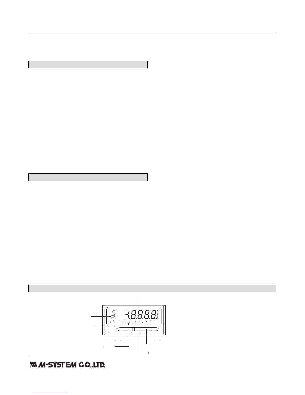
EXTERNAL VIEW
(4) Max/Min Button
(5) Alarm/ Button
(6) Scale/ Button
(7) Shift Button
(8) Up Button
(1) Main Display
(2) Alarm Indicators
(3) Function Indicators
Alarm/ Scale/Max/Min Shift Up
Zro
HH
H
P
L
LL
Spn D/P
Tch Fnc Min Max
 Loading...