

Page 1
MODEL: 40DN
http://www.m-system.co.jp/ 40DN SPECIFICATIONS ES-9534 Rev.3 Page 1/5
Digital Panel Meters 40 Series
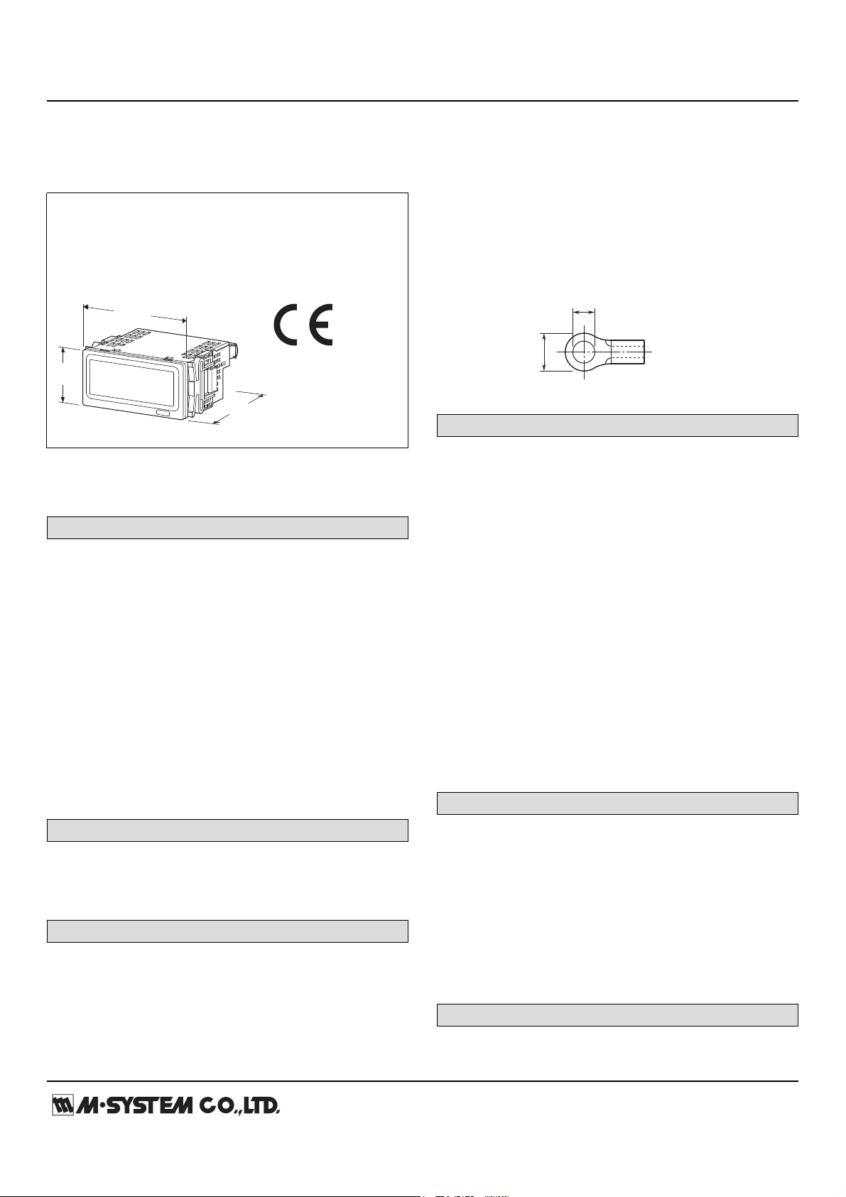
mm (inch)
96 (3.78)
48
(1.89)
96 (3.78)
6 (.24) max
3.3 (.13) max
mm (inch)
LOOP POWERED DIGITAL PANEL METER
(4 digits, process meter)
Functions & Features
• 4 digit (±9999) loop powered panel meter
• No external power source needed
• Scaling function
• High visible, 0.8" (20.3 mm) high and bright LED
MODEL: 40DN[1]
ORDERING INFORMATION
• Code number: 40DN[1]
Specify a code from below for [1].
(e.g. 40DN/Q)
• Specify the specification for option code /Q
(e.g. /SET)
INPUT
Current
4 – 20 mA DC
[1] OPTIONS
blank: none
/Q: With options (specify the specification)
SPECIFICATIONS OF OPTION: Q
EX-FACTORY SETTING
/SET: Preset according to the Ordering Information Sheet
(No. ESU-9534)
GENERAL SPECIFICATIONS
Construction: Panel flush mounting
Connection: M3 screw terminals (torque 0.6 N·m)
Solderless terminal: Refer to the drawing at the end of the
section.
Recommended manufacturer: Japan Solderless Terminal
MFG.Co.Ltd, Nichifu Co.,ltd
Applicable wire size: 0.25 to 1.65 mm2 (AWG 22 to 16)
Screw terminal: Nickel-plated steel
Housing material: Flame-resistant resin (gray)
A/D conversion: Σ – Δ
Sampling rate: 10 times/sec. (100 msec.)
Averaging: None or moving average
Setting: (Front button)
• Scaled range
• Moving average
• Brightness
■Recommended solderless terminal
DISPLAY
Display: 4 digits of 20.3 mm (0.8 inch) height, 7-segment,
red LED
Display range: -9999 to 9999
Scaling range for measurement range (4 - 20 mA): -9999 to
9999 counts
Decimal point position: 10-1, 10-2, 10-3 or none
Zero indication: Higher-digit zeros are suppressed.
Over-range indication: '-9999' or '9999' blinking for display
values out of the scaled range. 'S.ERR' blinks surpassing
the permissible range.
Engineering unit indication: Sticker label attached
DC, AC, mV, V, kV, μA, mA, A, kA, mW, W,
kW, var, kvar, Mvar, VA, Hz, Ω, kΩ, MΩ,
cm, mm, m, m/sec, mm/min, cm/min, m/min,
m/h, m/s2, inch, ℓ, ℓ/s, ℓ/min, ℓ/h, m3, m3/sec,
m3/min, m3/h, Nm3/h, N·m, N/m2, g, kg, kg/h,
N, kN, Pa, kPa, MPa, t, t/h, ℃, °F, %RH, J,
kJ, MJ, rpm, sec, min, pH, %, ppm, etc.
INPUT SPECIFICATIONS
■ DC Current
Current range: Approx. 3.7 to 23 mA DC
Voltage drop: Approx. 5 V with 4 mA; approx. 5.2 V with 20
mA (Equivalent input impedance: Approx. 260 Ω)
(There is voltage drop generated by using the unit. For the
two-wire transmitter power supply, make sure that the
operable voltage for the two-wire transmitter is ensured
including the voltage drop by other devices and wiring
resistance.)
INSTALLATION
Operating temperature: -10 to +55°C (14 to 131°F)
Operating humidity: 30 to 90 %RH (non-condensing)
Page 2
MODEL: 40DN
http://www.m-system.co.jp/ 40DN SPECIFICATIONS ES-9534 Rev.3 Page 2/5
Mounting: Panel flush mounting
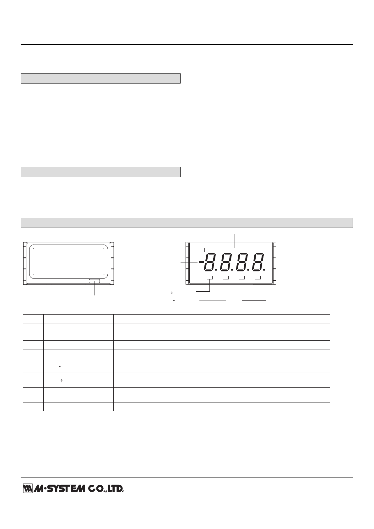
(2) Sticker Label
(1) Front Panel
(5) Disp/ Button
(3) 4-digit Display
(4) Polarity Indicator
(6) Scale/ Button
(8) Up Button
(7) Shift Button
■COMPONENT IDENTIFICATION
No. COMPONENT FUNCTIONS
(1)
Front panel Removed at configuration.
(2)
Sticker label Engineering unit label position
(3)
4-digit display 4-digit LED display. Range: 0 to 9999 (not including decimal point)
(4)
Polarity indicator Turns on when negative value is displayed
(5)
Used to move on to the display setting modes; or to shift through setting items in each
setting mode.
(6)
Used to move on to the scaling setting modes; or to shift through setting items in each setting mode.
(7)
Shift button
Used to move on to the setting standby status and shift through display digits in each setting item.
(8)
Up button Used to select setting value.
Disp/ button
Scale/ button
Weight: 160 g (0.35 lb)
PERFORMANCE
Accuracy: ±0.1 % rdg ±1 digit ("±1 digit" is multiplied by
scaling-multiple. Even in case the scaling-multiple is less
than 1, multiply by 1.)
Temp. coefficient: ±(0.01 % rdg +0.3 digits)/℃
("±0.3 digits" is multiplied by scaling-multiple. Even in case
the scaling-multiple is less than 1, multiply by 1.)
Scaling-multiple = | (Display Scaling Value B - Display
Scaling Value A) ÷ (default Display Scaling Value B - default
Display Scaling Value A) |
STANDARDS & APPROVALS
CE conformity:
EMC Directive (2004/108/EC)
EMI EN 61000-6-4: 2007
EMS EN 61000-6-2: 2005
EXTERNAL VIEW
Page 3

MODEL: 40DN
http://www.m-system.co.jp/ 40DN SPECIFICATIONS ES-9534 Rev.3 Page 3/5
PARAMETER LIST
...
...
PARAMETER
Display Scaling Value A
Display Scaling Value B
Decimal Point Position
3 positions or none Decimal point position
FUNCTION
DEFAULT
VALUE
DISPLAY
Display value for 20mA input
Display value for 4mA input
To distinguish from B, the first decimal
point is blinking.
A
0%
100%
0%
100%
B
Display
Input
Display Scaling
B
A
Display
Input
Display Scaling
• Normal Scaling
The display value increases when
the input signal increases.
• Inverted Scaling
The display value decreases when
the input signal increases.
The decimal point position can be set to any digit. Set it according to the 100% value.
PARAMETER
Moving Average
Brightness
Initialization Non-initialization
Brightness level 1 (dark)
Moving average with 2 samples
Brightness level 3 (bright)
Brightness level 2
No moving averaging
FUNCTION
DEFAULT
VALUE
DISPLAY
Initialize settings (change to factory settings)
*
1
Version Indication Version number, indication only– –
Moving average with 4 samples
Moving average with 8 samples
*1. While " " is shown, pressing Disp/ button or Scale/ button initializes settings.
Activating “initialization” of Lockout Setting Mode, Ex-factory settings (/SET) or user’s specified parameters will be deleted and overwritten
with the factory default values. Notice that after this, Ex-factory settings with will be irrecoverable.
■ SCALING SETTING MODE
■ DISPLAY SETTING MODE
Page 4

MODEL: 40DN
http://www.m-system.co.jp/ 40DN SPECIFICATIONS ES-9534 Rev.3 Page 4/5
DIMENSIONS unit: mm (inch)
92 (3.62)
45 (1.77)
85 (3.35)11
(.43)
96 (3.78)
96 (3.78)
48 (1.89)
103 (4.06)
10–M3 SCREW
TERMINALS
■ TOP VIEW
■ FRONT VIEW ■ SIDE VIEW
■ REAR VIEW
1 2 3 4 5 6 7 8 9 10
6.4 (.25)
92
+ 0.8
– 0
45
+ 0.6
– 0
min. 120
min. 75
Panel thickness: 1.6 to 8.0 mm
MOUNTING REQUIREMENTS unit: mm
Page 5
MODEL: 40DN
http://www.m-system.co.jp/ 40DN SPECIFICATIONS ES-9534 Rev.3 Page 5/5
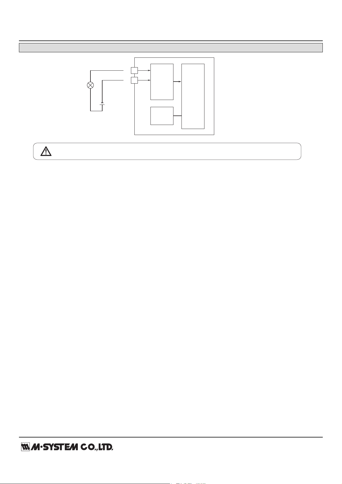
SCHEMATIC CIRCUITRY & CONNECTION DIAGRAM
+
–
2
1
INPUT
+
–
Two-wire Transmitter
Power Source
Digital
Computation
A/D
Converter
Display /
Setting
Specifications are subject to change without notice.
 Loading...