

Page 1
INSTRUCTION MANUAL
WIRELESS TOWER LIGHT
(small size, 60 mm dia., Modbus/TCP (Ethernet), Modbus-RTU transparent
900MHz band wireless device (parent), 0 – 5 lay
BEFORE USE ....
Thank you for choosing M-System. Before use, please check
contents of the package you received as outlined below.
If you have any problems or questions with the product,
please contact M-System’s Sales Office or representatives.
■ PACKAGE INCLUDES:
Tower Light .........................................................................(1)
Antenna ...............................................................................(1)
■ MODEL NO.
Confirm Model No. marking on the product to be exactly
what you ordered.
■ INSTRUCTION MANUAL
This manual describes necessary points of caution when
you use this product, including installation, connection and
basic maintenance procedures.
For information on the introduction of wireless device, refer
to the 900 MHz band wireless device operating manual
(EM-9085-B).
For information on the detailed setting, refer to the operating manual (EM-2431-B).
For information on Modbus specification, refer to the Modbus Protocol Reference Guide (EM-5650).
These manuals are downloadable at M-System’s web site
(http://www.m-system.co.jp).
POINTS OF CAUTION
■ POWER INPUT RATING & OPERATIONAL RANGE
• Locate the power input rating marked on the product and
confirm its operational range as indicated below:
24V DC rating: 24V ±10%, approx. 7.5W
PoE: 37 – 57V DC rating, approx. 7.5W
■ GENERAL PRECAUTIONS
• Before you remove the unit or mount it, turn off the power
supply and input signal for safety.
• The unit must not be subjected to external force.
• Do not rub the unit with organic solvent such as paint
thinner.
■ ENVIRONMENT
• Indoor use.
• Attach the antenna to the unit.
• Do not install the unit where it is subjected to continuous
vibration. Do not subject the unit to physical impact.
• Environmental temperature must be within -10 to +55°C
(14 to 131°F) with relative humidity within 10 to 90% RH
in order to ensure adequate life span and operation.
• Mount the unit on a flat and robust plate.
• Lamps are omnidirectional.
• The buzzer sound is directional in front of the unit.
• This unit communicates by radio waves. Do not install the
unit where it could be exposed to radio waves obstacles or
strong electric fields.
ers)
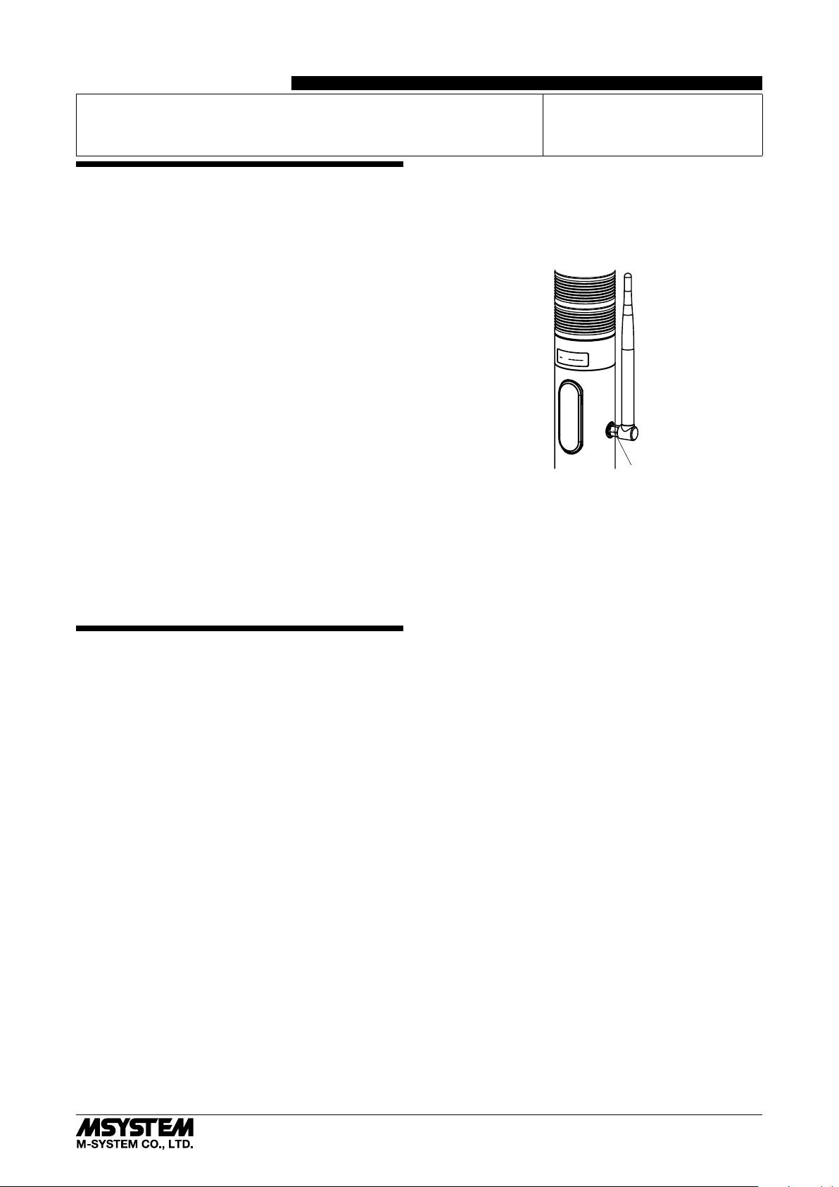
• How to change antenna angle: Rotate the antenna after
loosening the connector nut (refer to the next drawing).
Tighten the nut with torque (0.98 N·m) while holding the
antenna pointing to the intended direction. Otherwise,
tight manually the nut, and assure it turning 10° to 15°
more with a wrench.
■ INGRESS PROTECTION (IP65)
• The IP code is conformable when the unit is mounted vertically, antenna is installed and the control panel cover is
locked. The compartment, where connectors are located,
is not protected.
• When opening the control panel cover, avoid humidity
and dust penetration. Dry and clean it if condensation is
formed, and close the cover locking tightly.
• Install the antenna and tighten the connector nut tightly.
• In order to protect ingress of water or dust into the bottom compartment, mount the unit on the flat plane, and
be sure that the gasket does not roll back or dust is not
on the gasket.
■ WIRING
• Do not install cables close to noise sources (relay drive
cable, high frequency line, etc.).
• Do not bind these cables together with those in which
noises are present. Do not install them in the same duct.
• Cables to the unit must be wired indoor.
• Use an STP cable of category 5e or higher as an Ethernet
cable.
■ AND ....
• The unit is designed to function as soon as power is supplied, however, a warm up for 10 minutes is required for
satisfying complete performance described in the data
sheet.
PATLABOR
MODEL
™
IT60SW5F
Connector Nut
5-2-55, Minamitsumori, Nishinari-ku, Osaka 557-0063 JAPAN
Phone: +81(6)6659-8201 Fax: +81(6)6659-8510 E-mail: info@m-system.co.jp
EM-2433 P. 1 / 8
Page 2

CAUTION REGARDING RADIO FREQUENCY
■ FCC NOTICE
• This device complies with part 15 of the FCC Rules. Operation is subject to the following two conditions:
(1) This device may not cause harmful interference, and
(2) this device must accept any interference received, in-
cluding interference that may cause undesired operation.
■ FCC CAUTION
• Changes or modifications not expressly approved by the
party responsible for compliance could void the user’s authority to operate the equipment.
■ NOTE
• This equipment has been tested and found to comply with
the limits for a Class A digital device, pursuant to part 15
of the FCC Rules. These limits are designed to provide
reasonable protection against harmful interference when
the equipment is operated in a commercial environment.
This equipment generates, uses, and can radiate radio
frequency energy and, if not installed and used in accordance with the instruction manual, may cause harmful
interference to radio communications. Operation of this
equipment in a residential area is likely to cause harmful
interference in which case the user will be required to correct the interference at his own expense.
• This transmitter must not be co-located or operated in
conjunction with any other antenna or transmitter.
■ FCC RF EXPOSURE INFORMATION
• This equipment complies with FCC radiation exposure
limits set forth for an uncontrolled environment and
meets the FCC radio frequency (RF) Exposure Guidelines. This equipment should be installed and operated
keeping the radiator at least 20 cm or more away from
person’s body.
FCC ID : 2AOTF-0000005 (PoE)
FCC ID : 2AOTF-0000006 (24V DC)
Contains FCC ID: 2AKGW-1TD3016A1
IT60SW5F
5-2-55, Minamitsumori, Nishinari-ku, Osaka 557-0063 JAPAN
Phone: +81(6)6659-8201 Fax: +81(6)6659-8510 E-mail: info@m-system.co.jp
EM-2433 P. 2 / 8
Page 3
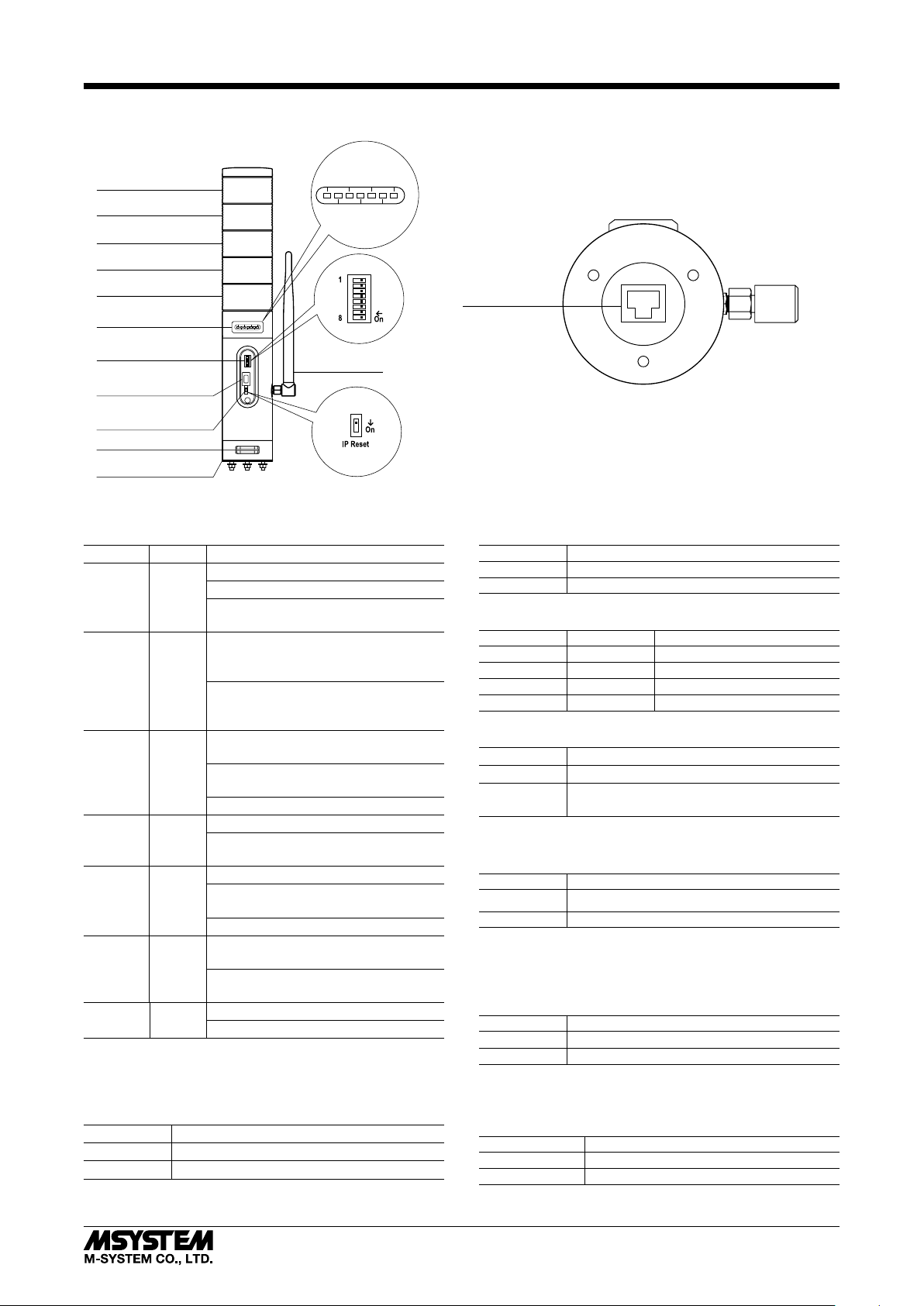
COMPONENT IDENTIFICATION
IT60SW5F
■ FRONT VIEW (with the cover open)
1
Lamp 1
Lamp 2
Power
Link 920Link
Run
Link100
PoE
920Run
*
Lamp 3
Lamp 4
Mode
Lamp 5
Status Indicator LED
Operating Mode Setting
DIP SW
Connector
for Maintenance
5
6
4
7
3
8
2
9
1
0
5
6
4
7
3
8
2
9
1
0
5
6
4
7
3
8
2
9
1
0
Antenna
IP Address Reset
Buzzer Aperture
Gasket
*1. Equipped when PoE is selected
■ STATUS INDICATOR LED
ID COLOR FUNCTION
Power Green On when power is supplied.
Blinks when the IP Reset SW is on.
Off when power is not supplied or an
abnormality occurs in the unit.
Run Green On when Modbus/TCP communication
is in normal status.
(For Modbus node address 255 only)
Off at Modbus/TCP communication
error or during no Modbus/TCP communication.
Link Green On when linking through 10 or 100
BASE.
Blinks when transmitting/receiving
data.
Off when there is no link.
Link100 Green On when linking through 100 BASE.
Off when linking through 10 BASE or
there is no link.
920Link Green On when wireless link is working.
Blinks with 0.5 Hz in establishing wireless link.
Off when wireless link stops working.
920Run Green On when wireless communication with
child device is in normal status.
Off at a wireless communication error
or during no communication.
PoE Green On when power is supplied via PoE.
Off when power is not supplied via PoE.
■ OPERATING MODE
(*) Factory setting
• Lamp Blinking Frequency: Mode-1
Mode-1 LAMP BLINKING FREQUENCY
OFF Approx. 2 Hz (*)
ON Approx. 10 Hz
■ BOTTOM VIEW
FRONT
Ethernet
Modular Jack
• Buzzer Intermittent Frequency: Mode-2
Mode-2 BUZZER INTERMITTENT FREQUENCY
OFF Approx. 2 Hz (*)
ON Approx. 10 Hz
• Buzzer Volume: Mode-3, Mode-4
Mode-3 Mode-4 BUZZER VOLUME
OFF OFF Quiet (*)
OFF ON Middle
ON OFF Loud
ON ON Maximum
• Output at the Loss of Communication: Mode-6
Mode-6 OUTPUT AT THE LOSS OF COMMUNICATION
OFF Reset the output (turned off) (*)
ON
Hold the output (maintains the last data
received normally)
Available when ‘Input Select’ is set to Modbus/TCP.
• Output Logic Reverse: Mode-7
Mode-7 OUTPUT LOGIC REVERSE
OFF Non-inverted (*)
ON Inverted
Available when ‘Input Select’ is set to Discrete input.
Not available with blink (BLINK) or intermittence (BUZZER2), be sure to turn it off.
• Input Select: Mode-8
Mode-8 INPUT SELECT
OFF Modbus/TCP (*)
ON Discrete input
Selects the input signal of lamp and buzzer control.
Note: Be sure to set unused Mode-5 to OFF.
■ IP ADDRESS RESET
IP RESET SW IP ADDRESS RESET
OFF Operating (*)
ON IP address returns to factory default
Note: Other network settings are also reset to default.
5-2-55, Minamitsumori, Nishinari-ku, Osaka 557-0063 JAPAN
Phone: +81(6)6659-8201 Fax: +81(6)6659-8510 E-mail: info@m-system.co.jp
EM-2433 P. 3 / 8
Page 4

WEB BROWSER SETTING
With Web browser, settings shown below are available.
Refer to the operating manual (EM-2431-B) for detailed settings.
■ DEVICE INFORMATION SETTING
ITEM SETTING RANGE DEFAULT
User name Up to any 32 characters admin
Password Up to any 32 characters admin
■ TCP / IP SETTING
ITEM SETTING RANGE DEFAULT
IP address 1.0.0.0 – 223.255.255.255 192.168.0.1
Subnet mask 224.0.0.0 – 255.255.255.255 255.255.255.0
Default gateway 0.0.0.0 – 255.255.255.255 0.0.0.0
■ MODBUS / TCP SETTING
ITEM SETTING RANGE DEFAULT
Port 1 – 65535 502
Modbus exception response Not return 06 (BUSY), 0B (ERROR) /
Return 06 (BUSY), 0B (ERROR)
Communication timeout 0.0 – 3200.0 (sec.) 60.0 (sec.)
Run lamp timeout 0.0 – 3200.0 (sec.) 5.0 (sec.)
Return 06 (BUSY), 0B (ERROR)
IT60SW5F
■ WIRELESS SETTING
ITEM SETTING RANGE DEFAULT
PAN ID (group number) 0000 – FFFE (hexadecimal, 4 digits) 0000
Radio channel number 1 – 43ch 1ch
Network name English one-byte characters within 16 characters
(one-byte space, “-” , “_” , “ . ” , “@” are usable.)
Encryption key 0000...0 – FFFF...F
(hexadecimal, 32 digits)
Prefix 2000:0000:0000:0000 – 3FFF:FFFF:FFFF:FFFF 2000:0000:0000:0000
Transmitter power output 0.16 mW / 1 mW / 20 mW 20 mW
Device type in a network,
Number of devices in a network
Set network quality Standard (recommended) /
Network join mode V3-compatible mode / Fast join mode V3-compatible mode
Packet filtering None / Yes (polling type) Yes (polling type)
Filter timeout on polling 1.0 – 60.0 (sec.) 4.0 (sec.)
Setting mode of short address Range mode: 1 device (max. multi drop number)
920Run timeout 0.0 – 3200.0 (sec.) 5.0 (sec.)
Retry times before route switching Once / Twice / Three times Three times
Short address list setting Short address —
MAC address list setting MAC address —
Connection refusal list setting MAC address —
Note: For version confirmation of communication module, refer to the operation manual (EM-2431-B).
Child (fixed), 1 to 30 devices /
Child (fixed), 31 to 60 devices /
Child (fixed), 61 to 100 devices /
Child (fixed) + child (moving)
Frequency of route switching and delay (higher) /
Frequency of route switching and delay (highest)
Range mode: 1 to 4 devices (max. multi drop number)
Range mode: 1 to 8 devices (max. multi drop number)
Range mode: 1 to 16 devices (max. multi drop number)
Range mode: 1 to 31 devices (max. multi drop number)
List mode
MH920
0000...0
Child (fixed), 1 to 30 devices
Standard (recommended)
List mode
5-2-55, Minamitsumori, Nishinari-ku, Osaka 557-0063 JAPAN
Phone: +81(6)6659-8201 Fax: +81(6)6659-8510 E-mail: info@m-system.co.jp
EM-2433 P. 4 / 8
Page 5

TERMINAL CONNECTIONS
compartment.
Connect the unit as in the diagram below.
■ EXTERNAL DIMENSIONS unit: mm
60±1.5dia.
IT60SW5F
A±4
1– 6 lengths*
3 Bolts and Nuts (M4)
Control Panel Cover
Approx. 1500
(60)
43 ±1.5 dia.
Antenna
(85)
Lead wires
Lamp Layers
0
1
2
3
4
5
R165
A
192
224
256
288
320
352
(30 dia.)
■ MOUNTING REQUIREMENTS unit: mm
Wiring Hole 30 dia.*
43 dia.
3 Holes (5 dia.)
120°
Front
* Protect wires to prevent scratching them at the edge of the
*1. Consult M-System for other bolt length.
5-2-55, Minamitsumori, Nishinari-ku, Osaka 557-0063 JAPAN
Phone: +81(6)6659-8201 Fax: +81(6)6659-8510 E-mail: info@m-system.co.jp
EM-2433 P. 5 / 8
Page 6

■ CONNECTION DIAGRAM
IT60SW5F
• PoE SUPPLY
To other PoE supported
Ethernet devices
INPUT
Connector for maintenance
Antenna Connector
RJ-45 Modular Jack
LAMP 1 INPUT
LAMP 2 INPUT
LAMP 3 INPUT
LAMP 4 INPUT
LAMP 5 INPUT
BUZZER INP 1
Continuance
BUZZER INP 2
Intermittence
LAMP BLINK
COM
2
*
Red
Amber
*
Green
2
*
Blue
*
White
Purple
Cyan
Brown
Orange
USB Connector
2
*
2
2
*
LAMP1
*
LAMP2
*
LAMP3
*
LAMP4
*
LAMP5
BUZZER1
BUZZER2
BLINK
COM
1
1
1
1
1
*1. Example of 5 layers in order: red, amber, green, blue and white.
Lamp and wire color are the same.
*2. When selecting the same color for more than one layer, cable colors
comply with ordering information sheet.
• DC POWER SUPPLY
To other Ethernet devices
LAMP 1 INPUT
LAMP 2 INPUT
LAMP 3 INPUT
LAMP 4 INPUT
INPUT
POWER
LAMP 5 INPUT
BUZZER INP 1
Continuance
BUZZER INP 2
Intermittence
LAMP BLINK
COM
FE
Connector for maintenance
*
Red
Amber
Green
Blue
White
Purple
Cyan
Brown
Orange
Gray
Black
Green/Amber
Antenna Connector
RJ-45 Modular Jack
2
2
*
2
*
2
*
2
*
LAMP1
LAMP2
LAMP3
LAMP4
LAMP5
1
*
1
*
1
*
1
*
1
*
BUZZER1
BUZZER2
BLINK
COM
U (+)
V (–)
FE1
USB Connector
• WIRING TO INPUT SIGNAL
Contact input e.g.
BLINK
Note: If “On” and “Blink” are set simultaneously for a single lamp, “Blink” is disabled.
At this time, if other lamps are being set to "Blink", they are also affected and work in the same manner.
ON
NPN input e.g.
TOWER LIGHT TOWER LIGHT
LAMP1
LAMP2
LAMP3
LAMP4
LAMP5
BUZZER1
BUZZER2
BLINK
COM
ON
BLINK
LAMP1
LAMP2
LAMP3
LAMP4
LAMP5
BUZZER1
BUZZER2
BLINK
COM
5-2-55, Minamitsumori, Nishinari-ku, Osaka 557-0063 JAPAN
Phone: +81(6)6659-8201 Fax: +81(6)6659-8510 E-mail: info@m-system.co.jp
EM-2433 P. 6 / 8
Page 7

IT60SW5F
CHECKING ETHERNET CONNECTION
■ PREPARATION FOR NETWORK
Prepare PC, clients and other devices for the network.
1. Connect the unit and PC with a LAN cable.
2. Set PC’s IP address to 192.168.0. xxx (for example, 192.168.0.10) which does not duplicate with the unit. Then, set subnet
mask to 255.255.255.0. (The unit’s factory setting IP address: 192.168.0.1)
■ SETTING ON THE WEB BROWSER
1. Start the web browser. Enter the unit’s IP address after http:// in address bar. For the first-time connection, enter as shown
below using the factory setting IP address.
http://192.168.0.1/
Web browser (recommended): Microsoft Internet Explorer 11 or later
2. Enter user name and password. For the first time connection, enter “admin” in those fields.
3. For setting details, refer to the operating manual (EM-2431-B).
■ NETWORK CONNECTION
When the network is correctly installed and the connection is established, Link or Link100 LED turns ON or blinks.
■ CHECK TOWER LIGHT CONNECTION
Enter “ping command” from Command Prompt on the Windows as follows:
C:¥WINDOWS>ping ***.***.***.***
(***.***.***.***: Enter IP address in decimal.)
ping ***.***.***.*** with 32 bytes of data:
Reply from ***.***.***.*** : bytes = 32 time < 10ms TTL = 64
Reply from ***.***.***.*** : bytes = 32 time < 10ms TTL = 64
Reply from ***.***.***.*** : bytes = 32 time < 10ms TTL = 64
Reply from ***.***.***.*** : bytes = 32 time < 10ms TTL = 64
Ping statistics for ***.***.***.***
Packets: Sent = 4, Received = 4, Lost = 0 (0% loss)
Replies in case of normal connection are as shown above. If the connection cannot be established normally due to problems
as wrong IP address, etc., other replies such as ‘timeout’ will be received.
MODBUS FUNCTION CODES & SUPPORTED CODES
■ DATA AND CONTROL FUNCTIONS
CODE NAME
01 Read Coil Status Digital output from the slave (read/write)
02 Read Input Status Status of digital inputs to the slave (read only)
03 Read Holding Registers General purpose register within the slave (read/write)
04 Read Input Registers Collected data from the field by the slave (read only)
05 Force Single Coil Digital output from the slave (read/write)
06 Preset Single Registers General purpose register within the slave (read/write)
15 Force Multiple Coils Digital output from the slave (read/write)
16 Preset Multiple Registers General purpose register within the slave (read/write)
■ EXCEPTION CODES
CODE NAME
01 Illegal Function Unsupported function code
02 Illegal Data Address Unsupported address
06 Slave Device Busy Full request queue
11 Gateway Target Device Failed To Respond Error response from 900 MHz band wireless device (child) or time-out
Note: When 900 MHz band wireless device (child) returns an exception code other than the above, the exception code is transmitted
directly to upper devices.
5-2-55, Minamitsumori, Nishinari-ku, Osaka 557-0063 JAPAN
Phone: +81(6)6659-8201 Fax: +81(6)6659-8510 E-mail: info@m-system.co.jp
EM-2433 P. 7 / 8
Page 8

IT60SW5F
MODBUS I/O ASSIGNMENTS
■ MODBUS NODE ADDRESS 255
By sending Modbus query of node address 255 from Modbus/TCP master device connected to the unit, it is possible to perform
I/O operations for the unit’s lamps and buzzers. The unit sends a response to Modbus/TCP master device that sent the query.
ADDRESS DATA TYPE DATA
Coils (0X) 1 – 16 Digital Output (lamp, buzzer)
17 – 32 Reserved (unused)
Inputs (1X) 1 – 16 Digital Input (lamp, buzzer)
Input Registers (3X) ---- ---- Unused
Holding Registers (4X) ---- ---- Unused
■ OUTPUT DATA
Output 0
Output 1
Output 2
Output 3
Output 4
Output 5
Output 6
Output 7
Output 8
Output 9
Output 10
Output 11
Output 12
Output 13
Output 14
Output 15
015
Output 0
Output 1
•
•
•
Output 15
Lamp 1 0: Off, 1: On Input 0 Lamp 1 0: Off, 1: On
Lamp 2 0: Off, 1: On Input 1 Lamp 2 0: Off, 1: On
Lamp 3 0: Off, 1: On Input 2 Lamp 3 0: Off, 1: On
Lamp 4 0: Off, 1: On Input 3 Lamp 4 0: Off, 1: On
Lamp 5 0: Off, 1: On Input 4 Lamp 5 0: Off, 1: On
Buzzer 0: Off, 1: Continuous Input 5 Buzzer 0: Off, 1: Continuous
– – Input 6 – –
– – Input 7 – –
Lamp 1 0: Off, 1: Blinking Input 8 Lamp 1 0: Off, 1: Blinking
Lamp 2 0: Off, 1: Blinking Input 9 Lamp 2 0: Off, 1: Blinking
Lamp 3 0: Off, 1: Blinking Input 10 Lamp 3 0: Off, 1: Blinking
Lamp 4 0: Off, 1: Blinking Input 11 Lamp 4 0: Off, 1: Blinking
Lamp 5 0: Off, 1: Blinking Input 12 Lamp 5 0: Off, 1: Blinking
Buzzer 0: Off, 1: Intermittent Input 13 Buzzer 0: Off, 1: Intermittent
– – Input 14 – –
– – Input 15 – –
■ INPUT DATA
015
Input 0
Input 1
•
•
•
Input 15
Note: If “On” (Continuous) and “Blinking” (Intermittent) are set simultaneously for a single lamp (buzzer), “Blinking” is disabled.
■ MODBUS NODE ADDRESSES 1 – 247
When Modbus query of Modbus node address 1 to 247 is sent from Modbus/TCP master device connected to the unit, it is
transferred to a wireless device (child) that is connected to the unit via 900 MHz band wireless communication, then a response from the wireless device (child) is sent to Modbus/TCP master device that sent the query.
5-2-55, Minamitsumori, Nishinari-ku, Osaka 557-0063 JAPAN
Phone: +81(6)6659-8201 Fax: +81(6)6659-8510 E-mail: info@m-system.co.jp
EM-2433 P. 8 / 8
 Loading...