

Page 1
INSTRUCTION MANUAL
WIRELESS INPUT UNIT
(
Modbus-RTU Transparent 900MHz Band Wireless Device (Child device),
Built-in I/O, 2-wire Transmitter Inputs 2 points
BEFORE USE ....
Thank you for choosing M-System. Before use, please check
contents of the package you received as outlined below.
If you have any problems or questions with the product,
please contact M-System’s Sales Office or representatives.
)
MODEL
WL40W1F-DS2
■ PACKAGE INCLUDES:
Wireless input unit .............................................................(1)
Antenna ...............................................................................(1)
■ MODEL NO.
Confirm Model No. marking on the product to be exactly
what you ordered.
■ INSTRUCTION MANUAL
This manual describes necessary points of caution when
you use this product, including installation, connection,
hardware setting, and basic maintenance procedures.
For information on the introduction of wireless device, refer to the 900MHz band wireless device operating manual
(EM-9085).
POINTS OF CAUTION
■ POWER INPUT RATING & OPERATIONAL RANGE
•Locate the power input rating marked on the product and
confirm its operational range as indicated below:
24 V DC rating: 24 V ±10%, ≤ 140 mA
■ GENERAL PRECAUTIONS
•Before you remove the unit or mount it, turn off the power
supply for safety.
■ ENVIRONMENT
•Indoor use.
•When heavy dust or metal particles are present in the
air, install the unit inside proper housing with sufficient
ventilation.
•Do not install the unit where it is subjected to continuous
vibration. Do not subject the unit to physical impact.
•Environmental temperature must be within -10 to +55°C
(14 to 131°F) with relative humidity within 10 to 90% RH
in order to ensure adequate life span and operation.
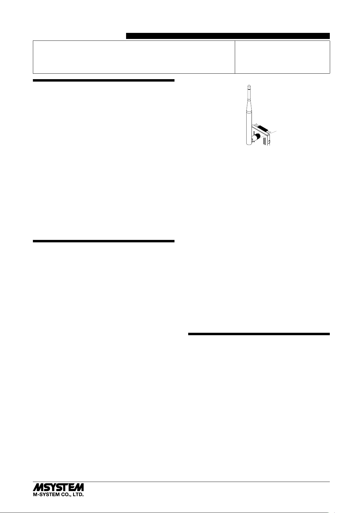
•Attach the antenna to the unit.
•Attachment and adjustment of sleeve antenna; Loosen
the connector (See the top-right figure.), and rotate the
antenna. Holding the antenna vertical, tighten the connector by hand.
•Make sure to fix the antenna firmly.
Connector
•Attachment of rooftop antenna; There is a magnet on the
bottom face which allows you to attach the antenna on
a metal box and such. To obtain optimum performance
from the antenna, attach on a metal plate (recommended
dimension: 500 mm × 500 mm or more). However, in the
case of connecting FE1 to a metal plate, the isolation between FE1 and antenna connector will be lost. Tighten
the connector with a specified torque (0.9 N∙m). As a
guide, finger-tighten it until the connector stops, and then
rotate it 10 to 15 degrees with a wrench. Do not force the
cable to bend less than acceptable radius of 3 cm.
•Using 7.5 m coaxial cable (model: CX-SAC0SAD0Q0750)
(OKI) for extension decreases transmission distance.
■ WIRING
•Do not install cables close to noise sources (relay drive
cable, high frequency line, etc.).
•Do not bind these cables together with those in which
noises are present. Do not install them in the same duct.
■ AND ....
•The unit is designed to function as soon as power is supplied, however, a warm up for 10 minutes is required for
satisfying complete performance described in the data
sheet.
CAUTION REGARDING RADIO FREQUENCY
■ FCC NOTICE
•This device complies with part 15 of the FCC Rules.
Operation is subject to the following two conditions:
(1) This device may not cause harmful interference, and
(2) this device must accept any interference received, including interference that may cause undesired operation.
■ FCC CAUTION
•Changes or modifications not expressly approved by the
party responsible for compliance could void the user’s authority to operate the equipment.
5-2-55, Minamitsumori, Nishinari-ku, Osaka 557-0063 JAPAN
Phone: +81(6)6659-8201 Fax: +81(6)6659-8510 E-mail: info@m-system.co.jp
EM-9084 P. 1 / 9
Page 2
WL40W1F-DS2
■ NOTE
•This equipment has been tested and found to comply with
the limits for a Class A digital device, pursuant to part 15
of the FCC Rules. These limits are designed to provide
reasonable protection against harmful interference when
the equipment is operated in a commercial environment.
This equipment generates, uses, and can radiate radio
frequency energy and, if not installed and used in accordance with the instruction manual, may cause harmful
interference to radio communications. Operation of this
equipment in a residential area is likely to cause harmful
interference in which case the user will be required to correct the interference at his own expense.
•This transmitter must not be co-located or operated in
conjunction with any other antenna or transmitter.
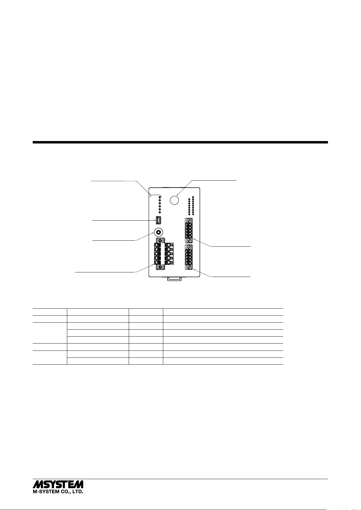
COMPONENT IDENTIFICATION
■ FRONT VIEW
Status Indicator LED
Power
920Link
920Run
920ERR
■ FCC RF EXPOSURE INFORMATION
•This equipment complies with FCC radiation exposure
limits set forth for an uncontrolled environment and
meets the FCC radio frequency (RF) Exposure Guidelines. This equipment should be installed and operated
keeping the radiator at least 20cm or more away from
person’s body.
FCC ID : 2AOTF-0000004
Contains FCC ID: 2AKGW-1TD3016A1
Antenna Connector
Maintenance Connector
Configuration Jack
Connector for Power Input
CFG2
CFG1
24V
0V
NC
NC
FE1
24V1
AI1A
AI1B
0V1
NC
24V2
AI2A
AI2B
0V2
NC
Input Connector 1
Input Connector 2
■ STATUS INDICATOR LED
ID STAT U S COLOR FUNCTION
Power ON Green Power is on.
920Link ON Green Wireless: coordinator is connected
0.5 Hz blinking Green Wireless: coordinator connection is in process
Blinking twice per second Green Wireless: start-up error
920Run ON Green Wireless: normal communication
920ERR ON Red No detour
Blinking Red Network authentication failure
5-2-55, Minamitsumori, Nishinari-ku, Osaka 557-0063 JAPAN
Phone: +81(6)6659-8201 Fax: +81(6)6659-8510 E-mail: info@m-system.co.jp
EM-9084 P. 2 / 9
Page 3
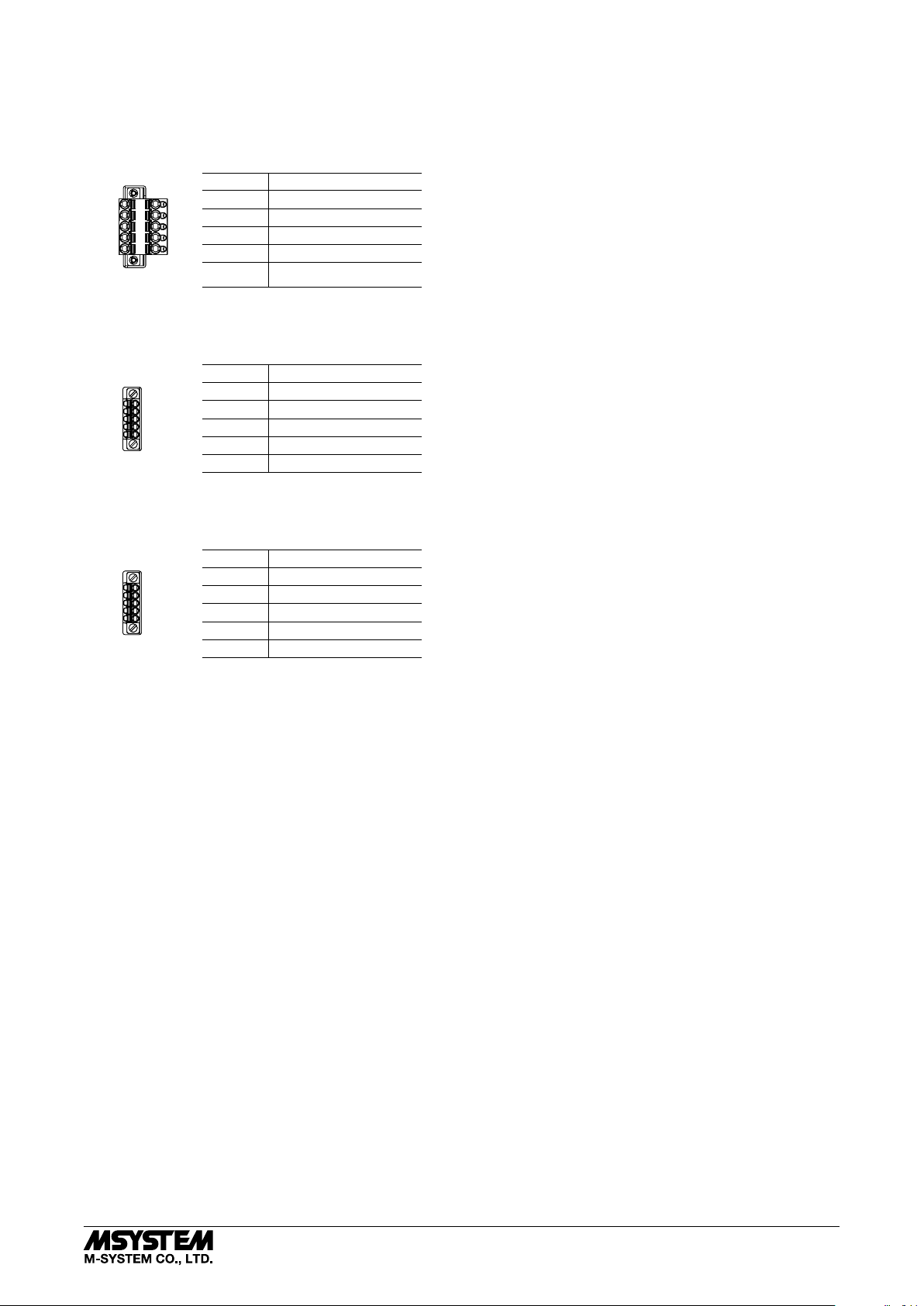
■ TERMINAL ASSIGNMENTS
• Connector for power input
Unit side connector: MSTBV2,5/5-GF-5,08AU (Phoenix Contact)
Cable side connector: TFKC2,5/5-STF-5,08AU (Phoenix Contact)
ID FUNCTION
24V
NC
NC
FE1
0V
24V Power input 24 V
0V Power input 0 V
NC Not used
NC Not used
FE1 Power input earth
• Input connector 1
Unit side connector: MC1,5/5-GF-3,5 (Phoenix Contact)
Cable side connector: FMC1,5/5-STF-3,5 (Phoenix Contact)
ID FUNCTION
24V1
AI1A
AI1B
0V1
NC
24V1 2-wire transmitter 1 +
AI1A 2-wire transmitter 1 –
AI1B Current input 1 +
0V1 Current input 1 –
NC Not used
• Input connector 2
Unit side connector: MC1,5/5-GF-3,5 (Phoenix Contact)
Cable side connector: FMC1,5/5-STF-3,5 (Phoenix Contact)
WL40W1F-DS2
24V2
AI2A
AI2B
0V2
NC
ID FUNCTION
24V2 2-wire transmitter 2 +
AI2A 2-wire transmitter 2 –
AI2B Current input 2 +
0V2 Current input 2 –
NC Not used
5-2-55, Minamitsumori, Nishinari-ku, Osaka 557-0063 JAPAN
Phone: +81(6)6659-8201 Fax: +81(6)6659-8510 E-mail: info@m-system.co.jp
EM-9084 P. 3 / 9
Page 4

WL40W1F-DS2
CONFIGURATOR SOFTWARE SETTING
With configurator software, settings shown below are available.
Refer to the users manual of W920FCFG for detailed operation.
■ WIRELESS SETTING
ITEM SETTING RANGE DEFAULT
Preferred PAN ID (group number) 0000 – FFFE (hexadecimal, 4 digits) 0000
Radio channel number 1 – 43 (selectable up to 10 channels) None
Short address 0000 – FFFD (hexadecimal, 4 digits) 0000
Network name English one-byte characters within 16 characters
(one-byte space, “-”, “_”, “.”, “@” are usable.)
Encryption key 0000...0 – FFFF...F
(hexadecimal, 32 digits)
Transmitter power output 0.16mW / 1mW / 20mW 20mW
Low-speed moving mode No / Yes No
Device type in a network,
Number of devices in a network
Set network quality Standard (recommended) /
Network join mode V3-compatible mode / Fast join mode V3-compatible mode
Fixed route No / Yes No
Destination short address 0000 – FFFD (hexadecimal, 4 digits) 0000
Temporary detour No / Yes Yes
Packet filtering None / Yes (polling type) Yes (polling type)
Filter timeout on polling 1.0 – 60.0 (sec.) 1.0 (sec.)
920Run timeout 1.0 – 60.0 (sec.) 3.0 (sec.)
Modbus node address 1 – 247 1
Retry times before route switching Once / Twice / Three times Three times
Child (fixed), 1 to 30 devices /
Child (fixed), 31 to 60 devices /
Child (fixed), 61 to 100 devices /
Child (fixed) + child (moving)
Frequency of route switching and delay (higher) /
Frequency of route switching and delay (highest)
* For version confirmation of communication module, refer to the users manual of W920FCFG.
Blank
0000...0
Child (fixed), 1 to 30 devices
Standard (recommended)
■ INPUT SETTING
CHANNEL ITEM SETTING RANGE DEFAULT
Analog input 1 Input enabled / disabled Enabled / Disabled Enabled
Zero input value 4.000 – 20.000 4.000 (mA)
Full input value 4.000 – 20.000
(full input value > zero input value)
Fine zero adjustment -5.00 – +5.00 (%) 0.00 (%)
Fine gain adjustment 0.9500 – 1.0500 1.0000
Zero scaling value -32000 – +32000 0
Full scaling value -32000 – +32000 10000
First-order filter time constant 0.0 – 60.0 (sec.) 0.0 (sec.)
Analog input 2 Input enabled / disabled Enabled / Disabled Enabled
Zero input value 4.000 – 20.000 4.000 (mA)
Full input value 4.000 – 20.000
(full input value > zero input value)
Fine zero adjustment -5.00 – +5.00 (%) 0.00 (%)
Fine gain adjustment 0.9500 – 1.0500 1.0000
Zero scaling value -32000 – +32000 0
Full scaling value -32000 – +32000 10000
First-order filter time constant 0.0 – 60.0 (sec.) 0.0 (sec.)
20.000 (mA)
20.000 (mA)
5-2-55, Minamitsumori, Nishinari-ku, Osaka 557-0063 JAPAN
Phone: +81(6)6659-8201 Fax: +81(6)6659-8510 E-mail: info@m-system.co.jp
EM-9084 P. 4 / 9
Page 5

INSTALLATION
■ DIN RAIL MOUNTING
A) Hang the upper hook at the back of the unit on the DIN
rail.
B) Push the lower part of the unit to fit in the DIN rail.
WL40W1F-DS2
■ DEMOUNTING
A) Pull down the DIN rail adaptor using a minus screw-
driver.
B) Pull out the lower part of the unit.
C) Remove the upper part from the DIN rail.
B
A
C
B
A
5-2-55, Minamitsumori, Nishinari-ku, Osaka 557-0063 JAPAN
Phone: +81(6)6659-8201 Fax: +81(6)6659-8510 E-mail: info@m-system.co.jp
EM-9084 P. 5 / 9
Page 6

TERMINAL CONNECTIONS
Connect the unit as in the diagram below.
■ EXTERNAL DIMENSIONS unit: mm (inch)
● WITH SLEEVE ANTENNA
[R165(6.50)]
[260 (10.24)]
WL40W1F-DS2
[155 (6.10)]
DIN RAIL
35mm wide
105 (4.13)
5 (.20)
60 (2.36)
● WITH ROOFTOP ANTENNA
[200 (7.87)]
80 (3.15)
36 (1.42)
3 (0.12) dia.
1.2 (.05) dia.
(1.06)
8 (.31) Hex.
approx. 2500 (98.4)27 dia.
107 (4.21) 3 (.12)45 (1.77)
DIN RAIL
35mm wide
(.79)
5-2-55, Minamitsumori, Nishinari-ku, Osaka 557-0063 JAPAN
Phone: +81(6)6659-8201 Fax: +81(6)6659-8510 E-mail: info@m-system.co.jp
107 (4.21) 3(.12)20
EM-9084 P. 6 / 9
Page 7

■ CONNECTION DIAGRAM
WL40W1F-DS2
Maintenance Connector
Antenna Connector
USB Connector
24V
0V
Power Input
NC
Configuration Jack
INPUT 1
Jack
NC
FE1
24V1
2-WIRE TRANSMITTER
AI1A
AI1B
INPUT (CURRENT INPUT)
0V1
NC
INPUT 2
24V2
2-WIRE TRANSMITTER
AI2A
AI2B
INPUT (CURRENT INPUT)
0V2
NC
■ HANDLING OF THE UNUSED INPUT
Connect 5 kΩ (0.5 W) terminating resistor to the input terminal which is not used, as shown below.
5 kΩ (0.5 W)
24Vn
AInA
If the above step is not performed, input becomes -5% or less, and PLC and such show data error.
However, using PC configuration software (model: W920FCFG) enables the setting of the unused input without the above step.
WIRING INSTRUCTIONS
■ TENSION CLAMP (FRONT TWIN CONNECTION) FOR POWER INPUT
Applicable wire size: 0.2 to 2.5 mm
Stripped length: 10 mm
Recommended terminals:
AI0,25-10YE 0.25 mm
AI0,34-10TQ 0.34 mm
AI0,5-10WH 0.5 mm
AI0,75-10GY 0.75 mm
AI1-10RD 1.0 mm
AI1,5-10BK 1.5 mm
AI2,5-10BU 2.5 mm
2
(Phoenix Contact)
2
(Phoenix Contact)
2
(Phoenix Contact)
2
(Phoenix Contact)
2
(Phoenix Contact)
2
(Phoenix Contact)
2
(Phoenix Contact)
■ SEPARABLE TENSION CLAMP TERMINAL FOR INPUT
Applicable wire size: 0.2 to 1.5 mm
Stripped length: 10 mm
Recommended terminals:
AI0,25-10YE 0.25 mm
AI0,34-10TQ 0.34 mm
AI0,5-10WH 0.5 mm
AI0,75-10GY 0.75 mm
2
(Phoenix Contact)
2
(Phoenix Contact)
2
(Phoenix Contact)
2
(Phoenix Contact)
2
2
5-2-55, Minamitsumori, Nishinari-ku, Osaka 557-0063 JAPAN
Phone: +81(6)6659-8201 Fax: +81(6)6659-8510 E-mail: info@m-system.co.jp
EM-9084 P. 7 / 9
Page 8
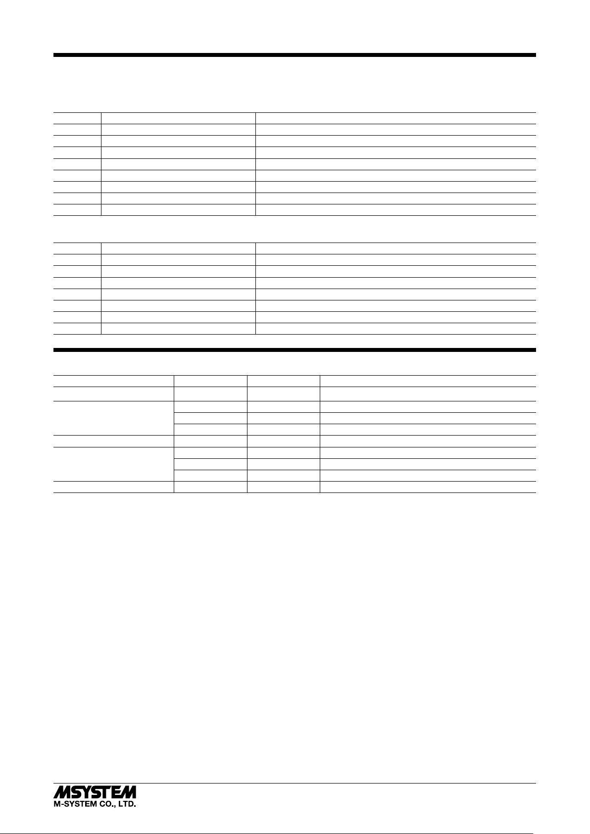
MODBUS FUNCTION CODE
Modbus function codes are shown below.
■ DATA AND CONTROL FUNCTION
CODE NAME
01 Read Coil Status Digital output from the slave (read / write)
02 Read Input Status Status of digital inputs to the slave (read only)
03 Read Holding Registers General purpose register within the slave (read / write)
04 Read Input Registers Collected data from the field by the slave (read only)
05 Force Single Coil Digital output from the slave (read / write)
06 Preset Single Registers General purpose register within the slave (read / write)
15 Force Multiple Coils Digital output from the slave (read / write)
16 Preset Multiple Registers General purpose register within the slave (read / write)
■ EXCEPTION CODE
CODE NAME
01 Illegal Function Function code is not allowable for the slave
02 Illegal Data Address Address is not available within the slave
03 Illegal Data Value Data is not valid for the function
04 Slave Device Failure
05 Acknowledge
06 Slave Device Busy
07 Negative Acknowledge
WL40W1F-DS2
MODBUS I/O ASSIGNMENT
ADDRESS DATA TYPE DATA
Coil (0X) 1 – 16 Reserved (unused)
Input (1X) 1 – 8 Reserved (unused)
9 Analog input error (input range error of analog input 1)
10 Analog input error (input range error of analog input 2)
11 – 16 Reserved (unused)
Input Register (3X) 1 I Analog Input (analog input 1)
2 I Analog Input (analog input 2)
3 – 16 – Reserved (unused)
Holding Register (4X) 1 – 16 – Reserved (unused)
Note: DO NOT access addresses other than mentioned above. Such access may cause problems such as inadequate operation.
■ DATA TYPE
I: Integer -32768 – +32767
■ STATUS
1 bit: indicates input status.
Input range error ( Input range is out of the range -5 to +105% for scaling setting, or out of the range -32768 to +32767 .)
0: Normal 1: Error
5-2-55, Minamitsumori, Nishinari-ku, Osaka 557-0063 JAPAN
Phone: +81(6)6659-8201 Fax: +81(6)6659-8510 E-mail: info@m-system.co.jp
EM-9084 P. 8 / 9
Page 9

INPUT DATA
■ ANALOG DATA (16 BITS)
WL40W1F-DS2
15
When the scaling setting is initial value, the data is 0 to 10000 for input 0 to 100% setting.
If the input range is -5 to +105% (-500 to +10500) and that is out of range, the data is fixed to -500 or 10500.
Minus value is converted into negative values, represented in 2’s complements.
■
DATA ERROR STATUS
Data error status is indicated by 1 bit.
0: OFF 1: ON
0
LIGHTNING SURGE PROTECTION
M-System offers a series of lightning surge protector for
protection against induced lightning surges. Please contact
M-System to choose appropriate models.
5-2-55, Minamitsumori, Nishinari-ku, Osaka 557-0063 JAPAN
Phone: +81(6)6659-8201 Fax: +81(6)6659-8510 E-mail: info@m-system.co.jp
EM-9084 P. 9 / 9
 Loading...