

MSTRONIC PSE-SW8, PSE-SW8S, PSE-SW8D User Manual

PSE-SW8 series
8 Port PoE Switch (Endspan)
(Extend Ethernet and PoE)
USER’S MANUAL
MSTRONIC CO., LTD.

User’s Manual
MSE PSE-SW8 Series
MSTRONIC CO., LTD.
2
1. General Information..............................................................
2. Hardware Description...........................................................
LED Indicators.......................................................................................
Power Wiring ........................................................................................
Ethernet Port/PD Port Wiring………………………………………………
3. Network Application…………………………………………….
4. Technical Specification........................................................
3
3
3
6
7
9
10
User’s Manual
MSE PSE-SW8 Series
MSTRONIC CO., LTD.
3
1. General Information
The PSE-SW8 POE Switch family provides a PoE/Data input port that is compatible with 802.3af
and 802.3at (Type 1 and Type 2) and it has seven 10M/100M TX ports with PoE PSE function. In
addition to the ability to accept standard 48VDC power on the Ethernet input Port 8, the PSE-SW8
provides 2 secondary DC wire terminal input ports for PoE switch operation from 12VDC to 57
VDC. If powered the model via rear DC terminal, the PoE output voltage is equal to the input
voltage. The PoE Switch can be used as an Ethernet/PoE repeater to extend Ethernet data and DC
power up to 200 meters. This manual will help you install and maintain the PoE switch. Installation
of the PoE switch is very easy and you will begin to operate as soon as you are powered up.
The PSE-SW8 comes with DIN rail mounting adapters for ease of mounting in network cabinets.
2. Hardware Description
*LED Indicator
There are 18 LEDs on the PoE switch to indicate the power and operational status. The following
section describes the functions of each LED indicator.
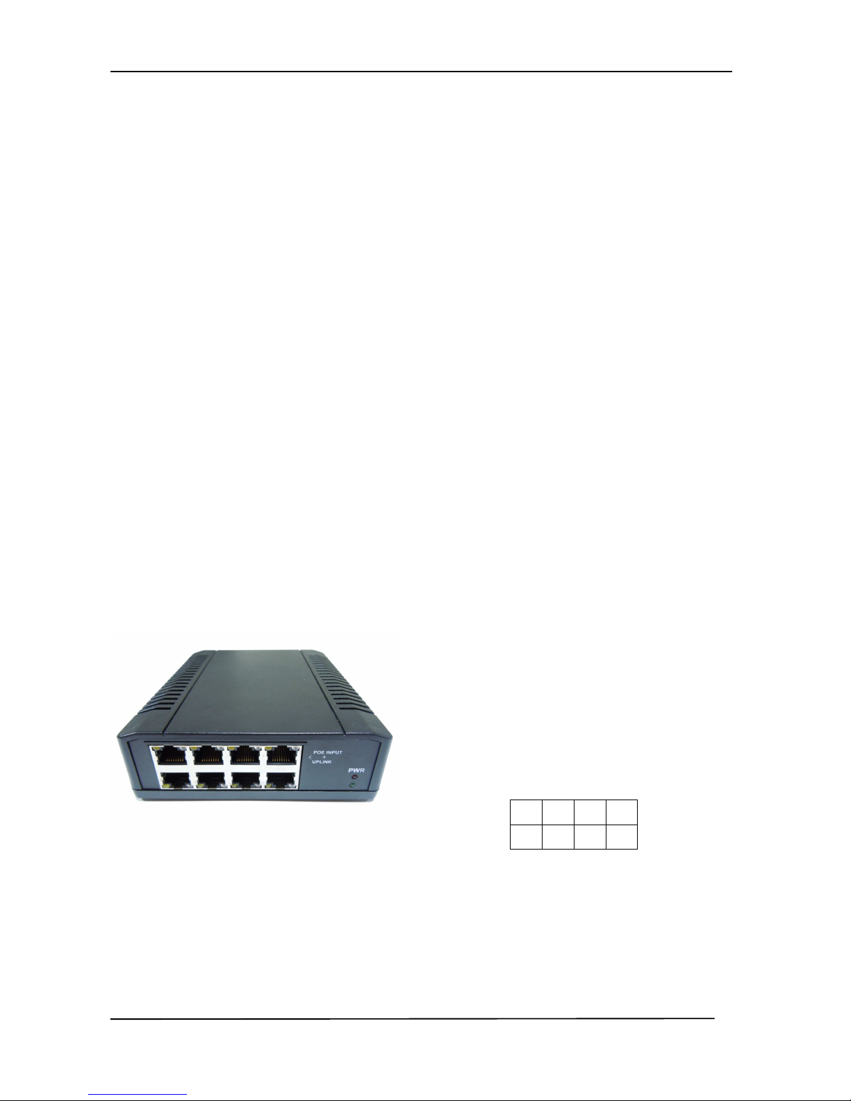
Front panel detail
the port number is as the diagram shows.
5 6 7 8
1 2 3 4
 Loading...