

MSTRONIC PSE-SW8G44A4, PSE-SW8G44B4, PSE-SW8G44D4 User Manual
USER’S MANUAL
MSTRONIC CO., LTD.
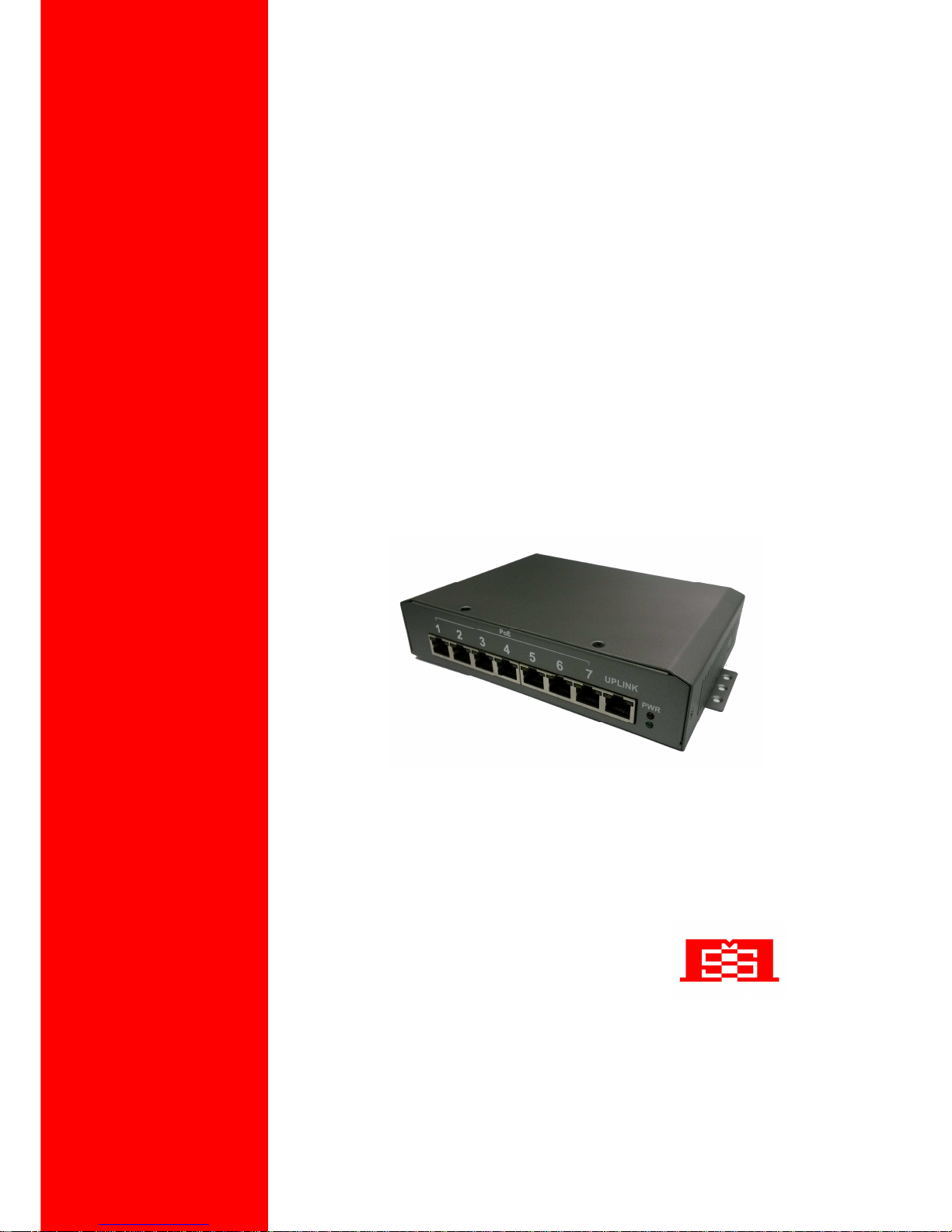
PSE-SW8G44xx
8 Port PoE Switch & Extender
User’s Manual
PSE-SW8G44xx series
MSTRONIC CO., LTD.
2
1. General Information
The PoE PSE-SW8G (Power Over Ethernet) Switch family provides seven 10M/100M/1000M TX
ports with PoE PSE function plus one 10M/100M/1000M TX up-link port with PoE PD function. It
allows power souring equipment (PSE) to be powered from PoE and delivers power to any PoE
powered device (PD), which is compliant with IEEE802.3af and IEEE802.3at standards to receive
and deliver both Ethernet data and DC power through the traditional UTP or STP cable. The PoE
Switch can extend Ethernet data and DC power up to 200 meters.
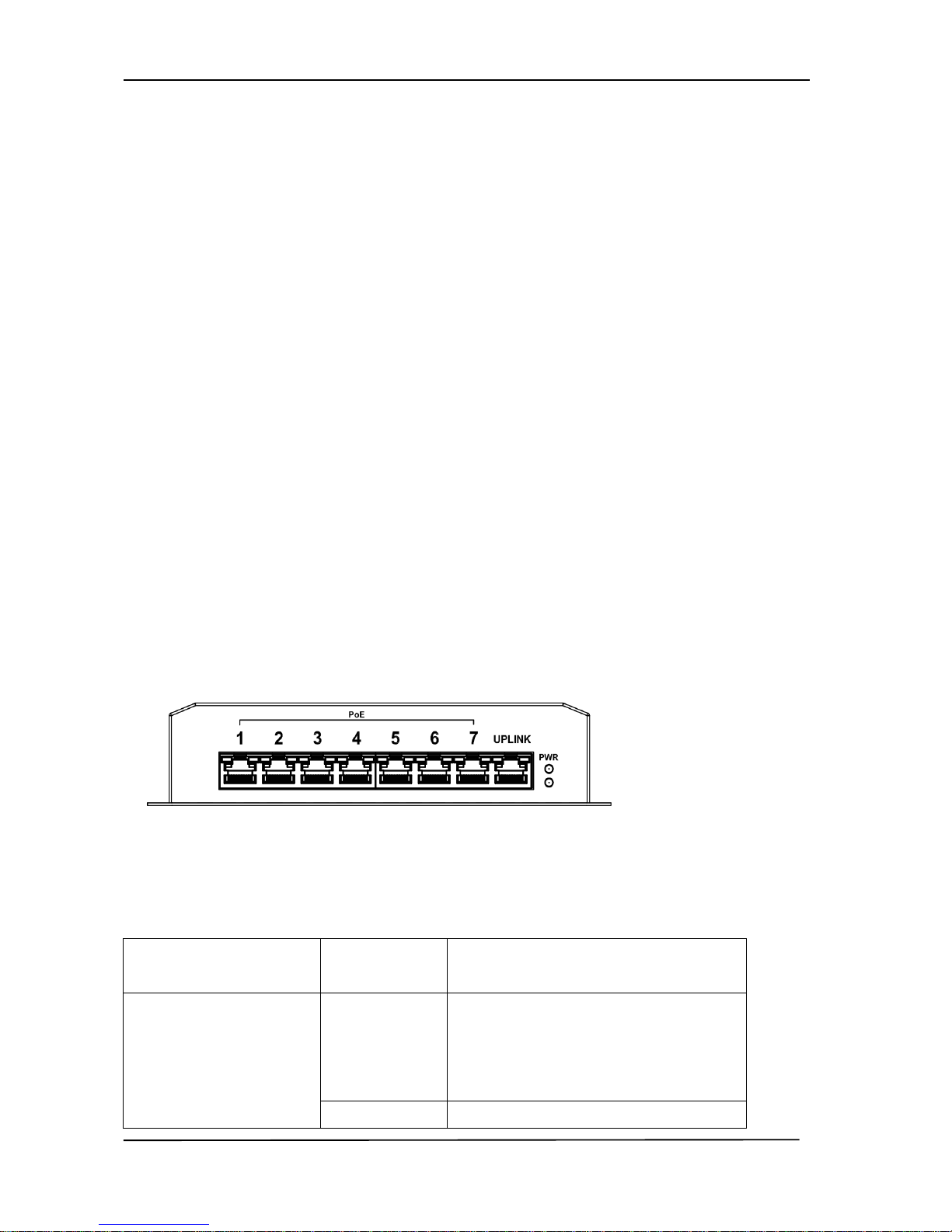
2. Hardware Description
*LED Indicator
There are 18 LEDs on the PoE switch to indicate the status of power and signal. The following
section describes the functions of each LED indicator.
Front panel detail
*POWER LED
LED
STATUS
Description
Power
Green
LED ON when power input (DC IN on
rear panel or Port 8 (UPLINK) on front
panel) has valid power supplied.
Off No power supplied.

User’s Manual
PSE-SW8G44xx series
MSTRONIC CO., LTD.
3
*SWITCH LED (the right indicator on RJ45)
LED STATUS Description
P1~P8
Link/Act
Green
A network device is detected (1000Mbps),
but no communication activity is detected.
Green
Blinking
This port is transmitting to, or receiving
package from another device at 1000Mbps.
Yellow A network device is detected (10Mbps or
100Mbps), but no communication activity
is detected.
Yellow
Blinking
This port is transmitting to, or receiving
package from another device at 10Mbps or
100Mbps.
Off No device is detected.
*PoE LED (the left indicator on RJ45)
P1~P7
PoE
Yellow
A valid Powered Device (PD) is detected
and delivering power on this port.
Off
No PD is detected on this port.
UPLINK (P8)
PoE
Yellow
powered via all 4 data pairs.
Yellow
Blanking
powered via 2 data pairs. (1,2,3,6 or 4,5,7,8
are all acceptable).
Off No power is detected on this port.

User’s Manual
PSE-SW8G44xx series
MSTRONIC CO., LTD.
4
*Power wiring
48VDC typical (44 to 57VDC) (P/N: PSE-SW8G44A4/PSE-SW8G44B4/PSE-SW8G44D4)
The PoE switch family can be powered by another PoE source on port 8 (UPLINK) as a PoE
repeater or extender.
For PSE-SW8G44xx, the range is 44~57VDC,
For PoE operation, make sure your power supply may offer at least 125W for 7x 802.3af PoE ports,
or 250W for 7x 802.3at PoE ports. The input voltage must be in the range of 44 to 57VDC if using
for 802.3af operation. The input voltage must be in the range of 50 to 57VDC if using for 802.3at
operation. If the PoE switch is not powered with the above designated input voltage, it will only
function as an Ethernet switch without PoE output.
In the full range voltage model, if powered via the rear terminal, please make sure the input current
is not over 15A. If powered on port 8, make sure the input current is not over 2Amps. (over 1A,
the gigabit signal will de-rate to 100M)
Ports 1~7 will deliver DC power over the Ethernet cable as detailed below:
In the A mode: * Data pair A plus V+ on line 1 and 2
* Data pair B plus V- on line 3 and 6
* Data pair C on line 4 and 5
* Data pair D on line 7 and 8
In the B mode: * Data pair A on line 1 and 2
* Data pair B on line 3 and 6
* Data pair C plus V+ on line 4 and 5
* Data pair D plus V- on line 7 and 8
Port 8 may get DC power over the Ethernet cable, as detailed below:
* Data pair A plus V+/V- on line 1 and 2
* Data pair B plus V-/V+ on line 3 and 6
* Data pair C plus V+/V- on line 4 and 5
* Data pair D plus V-/V+ on line 7 and 8
 Loading...